Walls
Design
Requirements for the design, manufacture and installation of embellishments
Good design
See the following corporate documents to identify relevant project design requirements:
Sunshine Coast Planning Scheme regulates the way land, buildings and structures are used and developed on the Sunshine Coast.

Sunshine Coast Design contains 10 design principles that guide good project planning and design outcomes, that are appropriate for the Sunshine Coast.
The LIM provides further overarching design advice, refer:
- Introduction and Design Principles - e.g. sustainability, CPTED, accessibility
- Preliminaries - environmental management, tree sensitive design and site set up.
Embellishment requirements
- Universal access.
- Comfortable and suitable for the average person.
- See 'Positioning' and 'Equal access' sections for the corresponding LIM category.
- Made from materials that will be durable and can be suitably protected from exterior elements, such as salt spray and UV exposure.
- Robust and sturdy to withstand constant public use and be resistant to vandalism.
- Fixings are to be 316 marine grade stainless steel (unless otherwise stated).
- Tamper proof fixings should be used
- Graffiti protection coatings applied (where applicable)
- Fire retardant (where applicable).
- Warranties should be as listed below.
- Easily repairable or replaceable.
- Sourced locally and use standard fittings.
- Reputable suppliers should be used who keep a supply of stock parts on hand for the life of the product.
- Use sustainable materials, although sustainability needs to be considered over the lifetime of the embellishment.
- Install on paved, concrete or other hard surfaces (where applicable).
- Manufactured to engineering specifications (where applicable).
- See the 'Standards' section for the corresponding LIM category.
Warranty and asset life
Product/embellishment | Warranty (minimum) | Asset life (typical useful life) |
timber walls | 15-25 years | 50 years 2 |
brick/block walls | 50 years | 80 years 2 |
stone/boulder walls | 25 years | 80 years 2 |
concrete walls | 10 years | 80 years 2 |
Source 2: Sunshine Coast Council Asset Management Plan 2017/18-2022/23 – Parks and Gardens (figure based on current data, subject to change).
Walls
Once the location of the wall has been decided, based on the Environment and Liveability Strategy (ELS) and Recreation Parks Plan (RPP) guidance, consider the appropriate embellishment level to suit the selected site.
Overarching design considerations:
- A wall is a solid structure which may act as a retaining wall, or it may be free standing and provide a base for signage and artwork, or act as a seating wall.
- Where a wall is over 1.0 m high, approvals are required.
- Walls should be designed and certified by an RPEQ.
Wall types
Walls can be used as a:
- Retaining wall
- Free-standing wall.
See Figure 1: Retaining wall and free-standing wall example
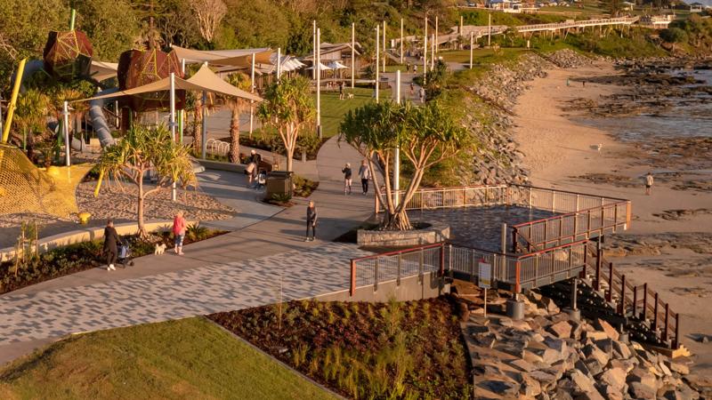
Figure 1: Retaining wall and free-standing wall example
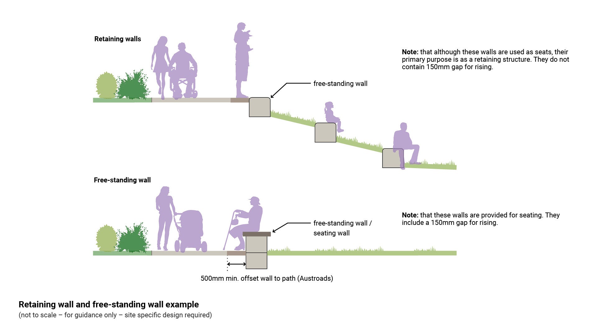
Retaining walls
Retaining walls are structures erected to support an excavated or filled embankment to prevent soil from collapsing. Certification by an RPEQ is required, and the wall (including footing) must be wholly within the subject lot. Uses include:
- To hold back soil between two or more different levels (the soil attempts to move down-slope due to gravity).
- To improve access to and maintenance of a slope, such as equal access and for mowing.
- Planter box to retain soil and contain plants.
- Where seepage is anticipated, to form a retaining structure such as gabion wire baskets filled with rock and wired together.
- Where a protective covering of an embankment is required to maintain the slope or protect it from erosion near a body of water (a revetment wall).
See the following:
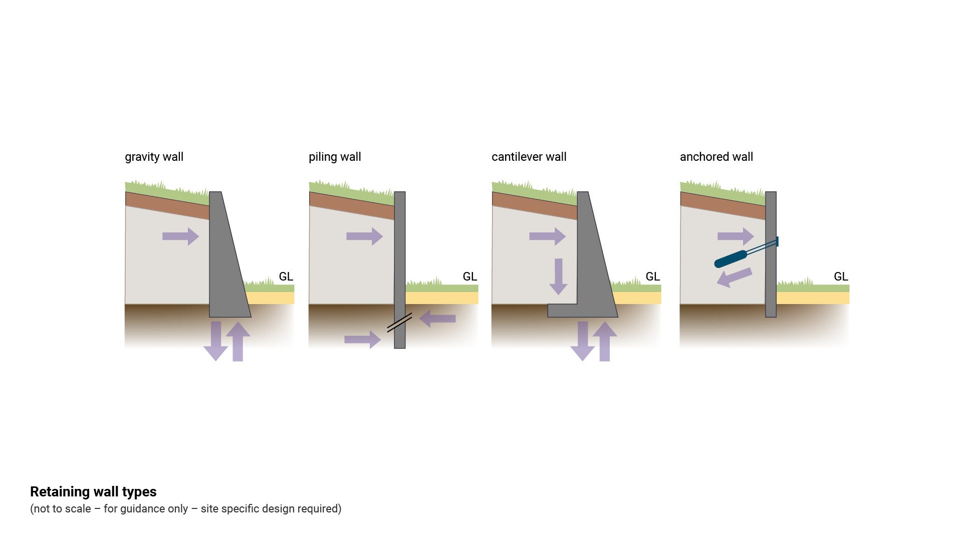
- Figure 2: Retaining wall types
- Figure 6: Identify barrier type/retaining wall barrier with handrail (see LIM Walls - Positioning).
Figure 2: Retaining wall types
Free-standing walls
Free-standing walls are structures which stand alone on their own footing and do not retain soil. Uses include:
- Barriers/divisions between different areas
- To delineate areas of different ownership
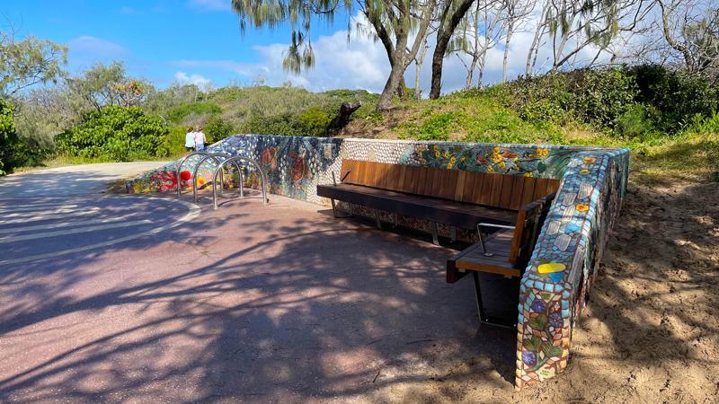
- Provide a backdrop on which to display artwork
- Memorial walls
- Seating walls
- Entry statement walls
- Signage walls.
Natural rock gravity walls or masonry faced walls are preferred:
- Walls which are retaining road or parkland are to be located within the road or parkland reserve.
- Walls located on public land must be provided with safety batters or child-proof fencing (depending on height).
See the following:
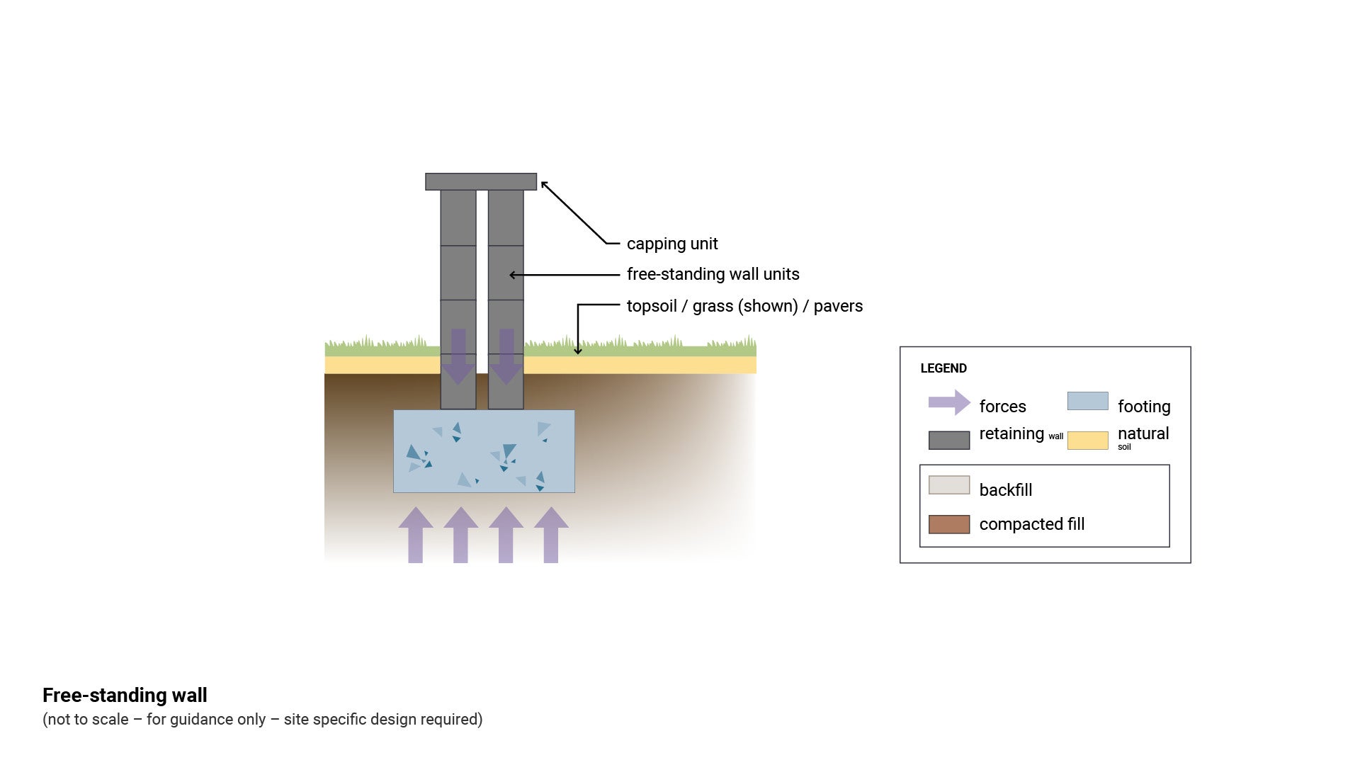
- Figure 3: Free-standing wall
- Figure 6: Identify barrier type/retaining wall barrier with handrail (see LIM Walls - Positioning)..
Figure 3: Free-standing wall
Wall design

Walls over 1.0 m high are to be certified fit for purpose by an RPEQ, or an acceptable generic masonry block design by a recognised manufacturer, and are to include the following design features:
- It is essential that the correct mix of mortar is used to prevent detachment of stones, rocks or other materials forming the wall.
- It is essential that drainage is designed correctly to prevent wall collapse and to channel water flow appropriately.
- The top of wall must be sealed to ensure no moisture can seep into the wall and diminish structural strength.
- Fixings and anti-skate devices are to be stainless steel.
- Walls for seating should be smooth at the top, between 450 mm and 520 mm high for adults.
- Walls with electricals housed inside (i.e. for lighting), must provide maintenance access for in-situ repairs.
- Where revetment walls and the like form part of, say, a grassed area through which there is unrestricted public access, refer to AS 2156.2 – Walking tracks Part 2 Infrastructure design for guidance about safety barrier types and ‘calculated fall height’.
Wall uses

Walls can be designed for the following uses.
See Table 1: Wall uses
Table 1: Wall uses
Wall type/use | Key consideration | Material |
Seating wall/planter 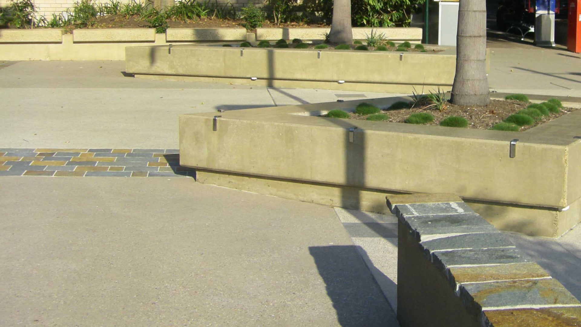 |
|
|
Barrier 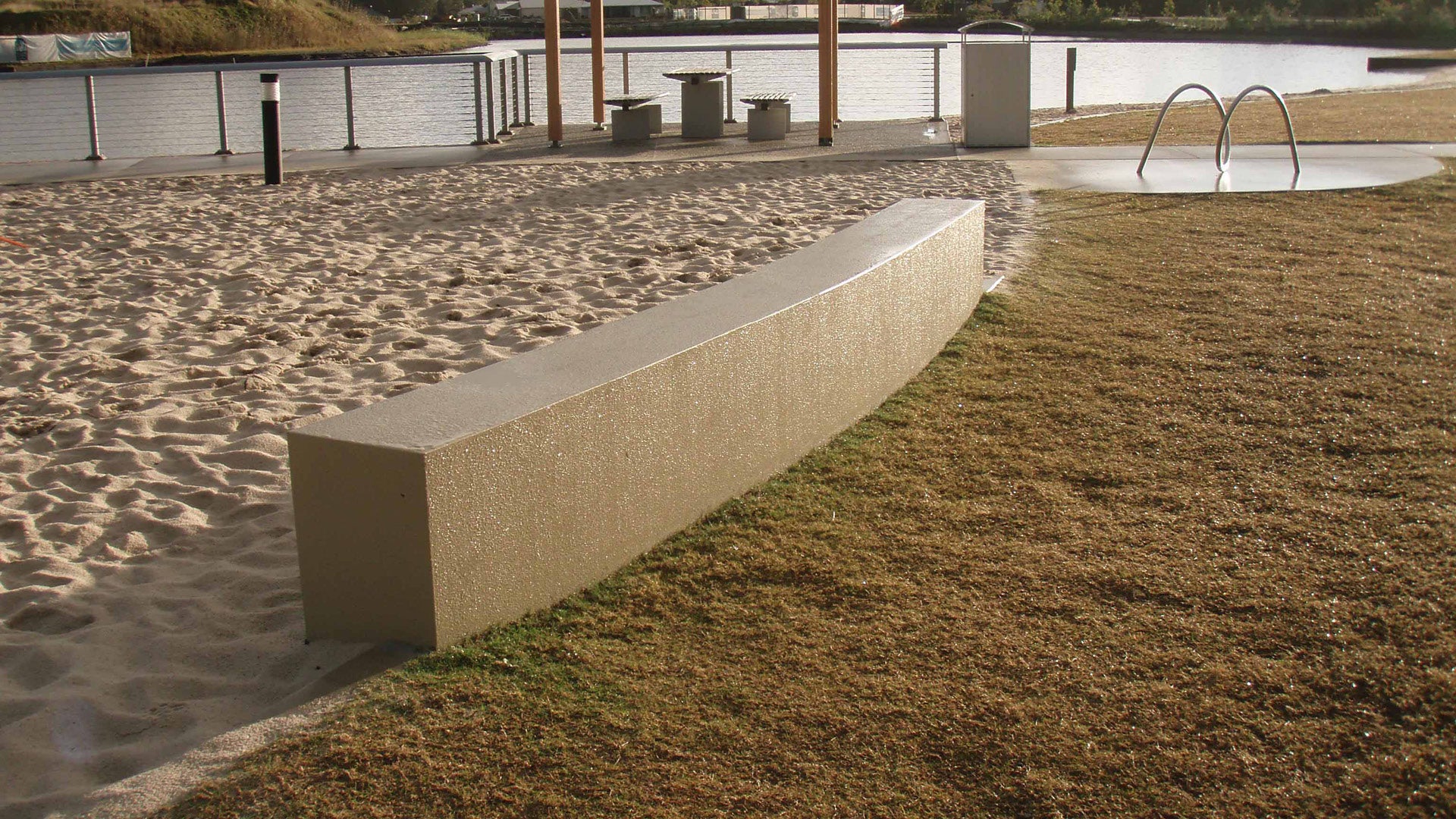 |
| as above |
Artwork  |
| as above |
Retaining/seating 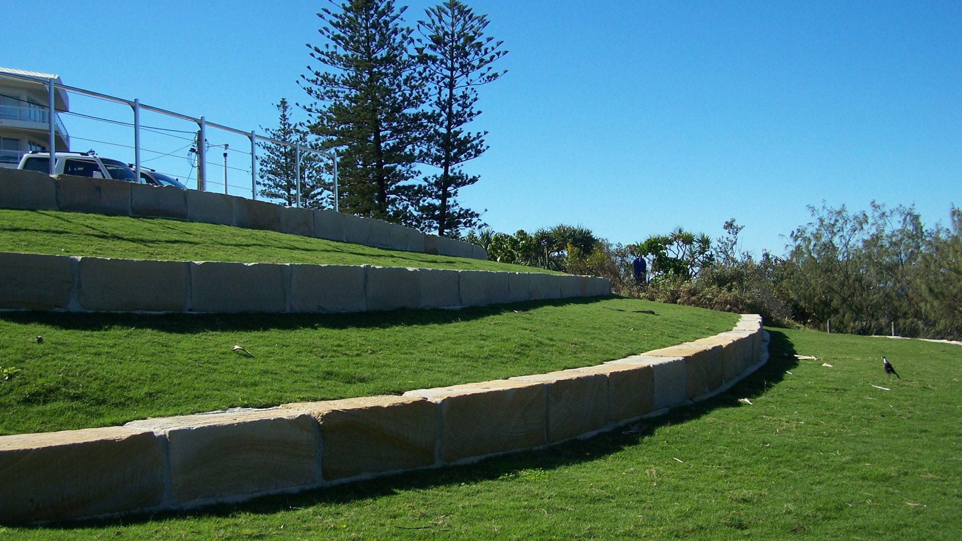 |
| as above |
Memorial 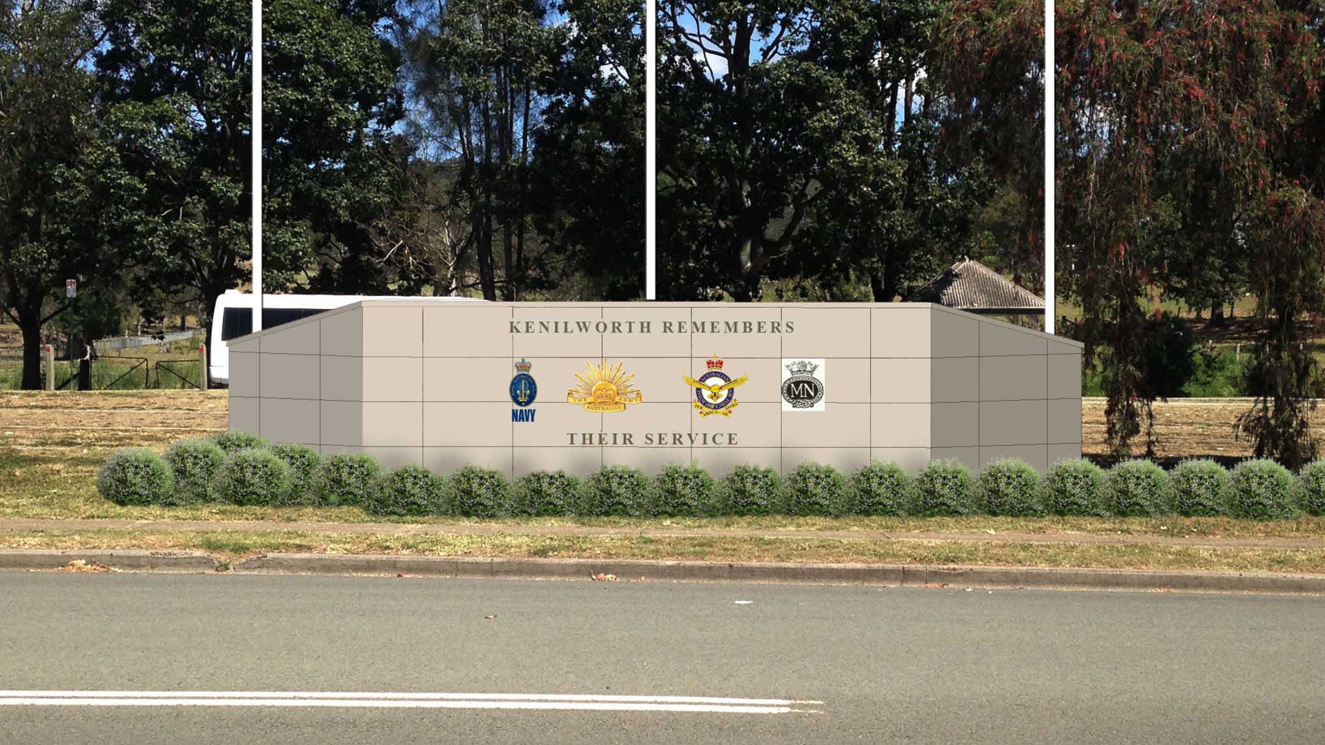 |
| as above |
Entry statement/sign/artwork 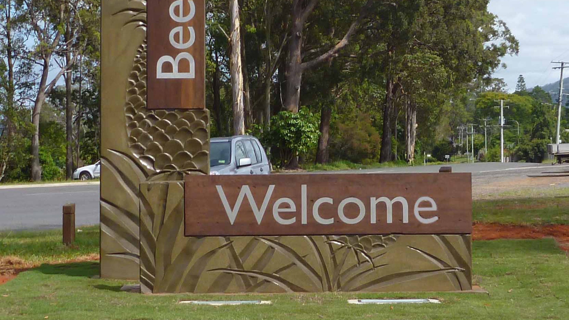 |
| as above |
Gabion 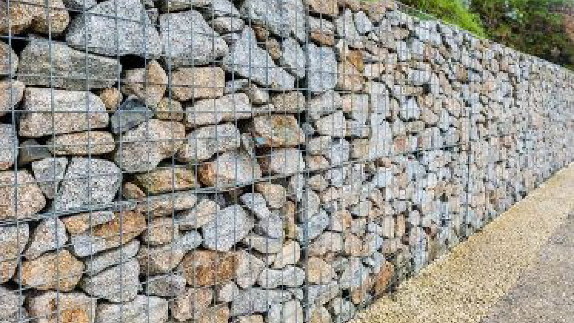 |
| Rock filled wire basket. |
Wall materials
Boulder walls (preferred)
A boulder wall is a free-form structure with the rocks placed in a random, natural way. Construction and materials are to comply with the following:
- Walls over 1.0 m high to be designed by a suitably qualified engineer.
- In geology, a boulder is a large rock with grain size usually no less than 300 mm. They may be small enough to move manually or extremely massive, requiring mechanical lifting.
- Excavator operator needs to be licensed, experienced, highly skilled, and capable of selecting boulders suitable for placement to ensure structural stability of the finished wall.
- Use an excavator fitted with a specialised rock grab to allow each individual rock to be turned to ensure it fits into the wall in the most stable and aesthetic manner.
- It is essential that drainage is designed correctly to prevent wall collapse and to channel water flow appropriately.
- Rocks should be sound and free from flaws including vents, cracks, fissures, foreign material, machine markings etc as these affect strength, appearance, durability, and proper functioning.
- Rock type should match any pre-existing works.
- Rocks are to be split faced, with the smooth undamaged surface used for the facing.
- Rockwork should be adequately bedded in mortar with minimal mortar exposed, with excess raked from joints without decreasing stability.
- Rock or stone cladding for wall facings and capping to be selected and split or worked to produce a consistent surface finish with joint size kept to an absolute minimum, unless stated on drawings.
- Rock sizes to be laid to allow for close bonding.
- All sharp faces to be chamfered leaving no machine markings and to replicate natural edge.
- Boulder walls to be formed by placing rocks on the ground while ground formation work is being carried out, using approved site and imported rocks, bury two thirds by volume, with weathered exposed faces protected from damage.
See the following:
- Figure 4: Boulder sizes.
Sandstone boulder wall

Figure 4: Boulder sizes
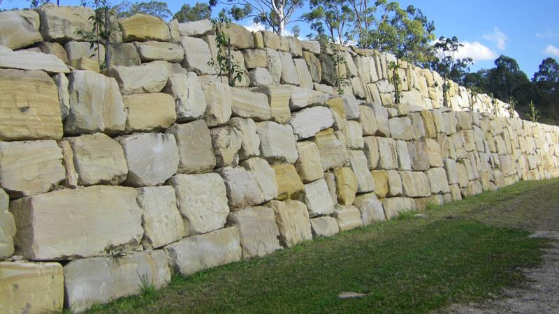
Sandstone block walls (preferred)
A sandstone block wall is constructed by placing rectangular blocks of sandstone end to end to create a retaining, seating or delineation wall.
Construction and materials are to comply with the following:
- The settlement of sediment results on the formation of horizontal layers/strata. All sandstone blocks must be laid the same way the rock was formed in the earth.
- Blocks should not be laid with sediment layers vertical. This allows weathering to permeate the exposed layers.
- Walls over 1.0 m high are to be designed by a suitably qualified engineer.
Laying
- Sandstone blocks requiring mechanical lifting. The excavator operator needs to be licensed, experienced, highly skilled, and capable of laying blocks so that the grain is predominantly horizontal, to ensure a natural look to the finished wall, and to resist weathering.
- Blocks should be adequately bedded onto a crushed rock footing to form a level surface.
- Lay linear sandstone block walls so that any gaps between blocks are grouted to prevent entrapment.
- Incorporate oxide colour in the grout to complement the sandstone.
- Sand/cement mortar maximum grouting jointing 100 mm wide.
Sandstone blocks can be positioned as stand alone or in a linear set out with grouting:
- Ensure stand alone sandstone blocks are laid with layers horizontal.
- When some sandstone types are laid with their horizons vertical (exposed to weathering, rainfall), moisture penetrates the horizons and expansion and splitting can occur. Broken fragments which shear off could become a safety issue.
Wheel sawn
Wheel sawn sandstone blocks are:
- a more formal finish
- more expensive than rough sawn.
- Consider grade ‘A’ wheel sawn blocks 1000 mm x 500 mm x 500 mm, for linear walls.
- Six wheel sawn faces are required to allow the flexibility to lay the stone so that graining is horizontal, and to match face colour/pattern.
- 20 mm arris is required to all exposed top edges and grind smooth any sharp/rough edges and corners.
Rough sawn
- Rough sawn sandstone blocks are:
- a more natural finish
- less expensive than wheel sawn.
- Consider that standard rough sawn sandstone blocks have five sides rough sawn with one side left rough. This finish removes the flexibility to lay the stone so that graining is horizontal.
See Figure 5: Typical sandstone block use.

Sandstone block wall
Sandstone blocks
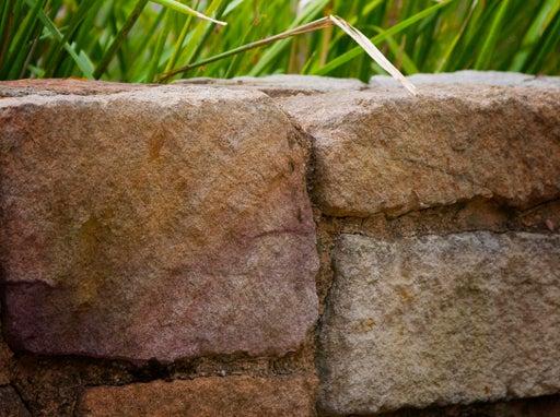
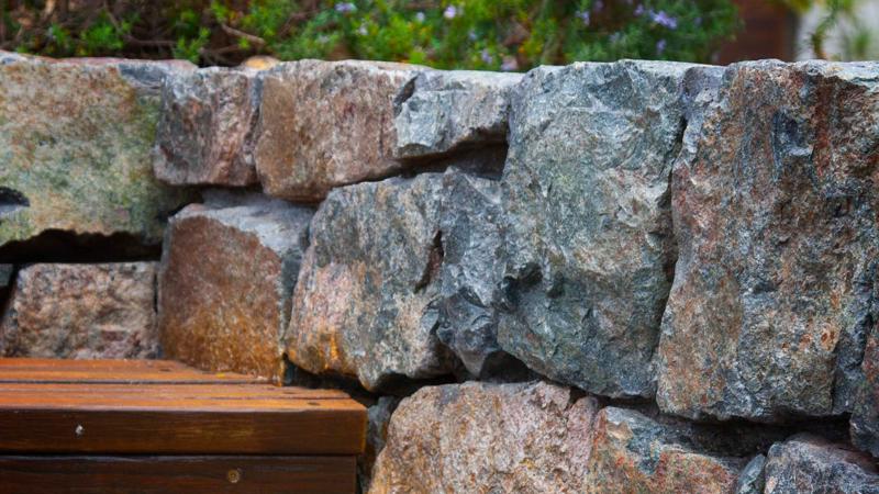
Rock walls (preferred)
Construction and materials are to meet the following:
- Walls over 1.0 m high to be designed by a suitably qualified engineer.
- Rock walls are to have a footing which is suitable for the site soil conditions and designed by a suitably qualified engineer.
- Rockwork should be adequately bedded in mortar with minimal mortar exposed, with excess raked from joints without decreasing stability.
- Rocks should be sound and free from flaws including vents, cracks, fissures, foreign material, machine markings etc as these affect strength, appearance, durability, and proper functioning.
- Rock type should blend with any pre-existing works.
- Rocks are to be split faced, with the smooth undamaged face used for the facing.
- Rock or stone cladding for wall facings and capping to be selected and split or worked to produce a consistent surface finish with joint size kept to an absolute minimum.
- Rock sizes to be laid to allow for close bonding.
- All sharp faces to be chamfered leaving no machine markings and to replicate natural edge.
- Where a retaining rock wall is to be used for seating, grout between rocks should be smooth and level.
- Where a free-standing rock wall is to be used for seating purposes, coping material should be smooth and near level.
- The top of wall must be sealed to ensure no moisture can seep into the wall and diminish structural strength.
- Fixings are to be stainless steel.
- Walls for seating should be between 450 mm and 520 mm high for adults.
- It is essential that the correct mix of mortar is used to prevent detachment of stones and rocks.

Rock tiled free-standing wall
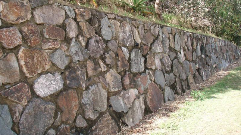
Grouted rock retaining wall

Sandstone faced free-standing wall
Rendered masonry walls (preferred)
Construction and materials are to meet the following:
- Walls over 1.0 m high are to be designed by a suitably qualified engineer.
- A masonry block wall is built from individual units laid in and bound together by mortar.
- The term masonry refers to the units themselves.
- The term render refers to the plaster applied to the masonry wall.
- Core filled masonry block walls are to have a footing which is suitable for the site soil conditions and designed by a suitably qualified engineer.
- Core filled masonry blocks are suitable as a base material on which to install painted render or tiles.
- Masonry wall facings and capping are to be selected for a consistent surface finish.
- Where a masonry wall is to be used for seating purposes, coping material should be smooth and near level.
- Where a masonry wall is to be used as a memorial wall, wall facing material should be smooth and symmetrical to facilitate fixing of plaques and badges.
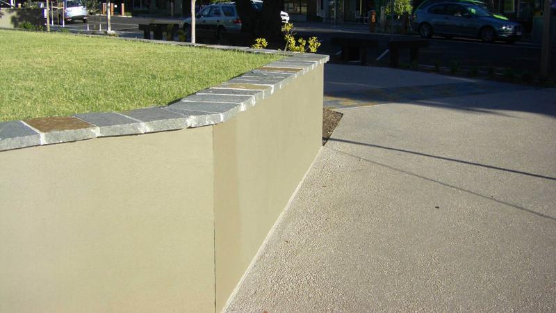
Rendered masonry retaining wall with tiled capping
Concrete sleeper walls
Construction and materials to meet the following:
- Concrete sleeper retaining walls are built from individual pre-cast concrete units laid in and fixed together by galvanised steel posts.
- A coloured concrete ‘wood look’ sleeper wall is constructed using matching concrete wood look posts.
- Concrete sleeper may be coloured using CCS concrete colours.
- ‘Wood look’ concrete railway sleeper and railway post are available in:
- rustic railway aged timber.
- brown.
- dark grey.
- plain grey.
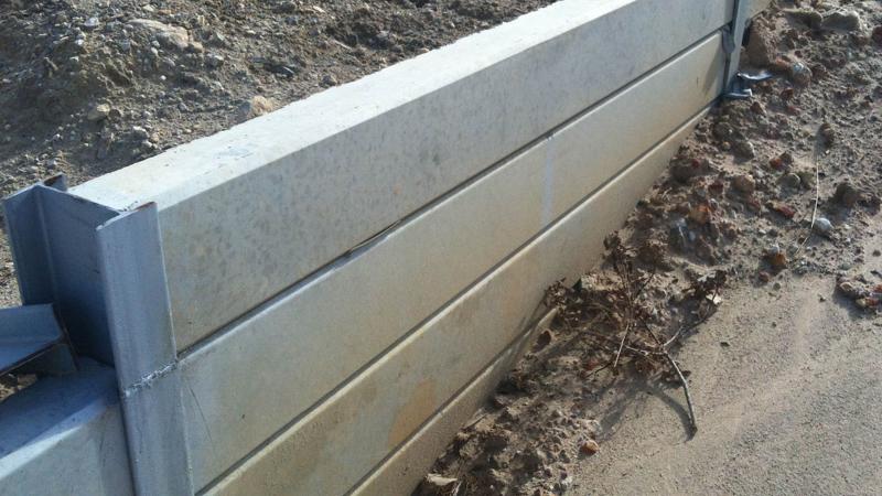
Plain concrete sleeper retaining wall
Stacked masonry (not preferred)
Stacked small masonry block retaining walls are not Council preferred, particularly where they are adjacent to pathways.
- Council incurs high ongoing maintenance costs caused by replacement of blocks due to vandalism (removal).
- It is difficult to match the colour of removed blocks.

Stacked masonry
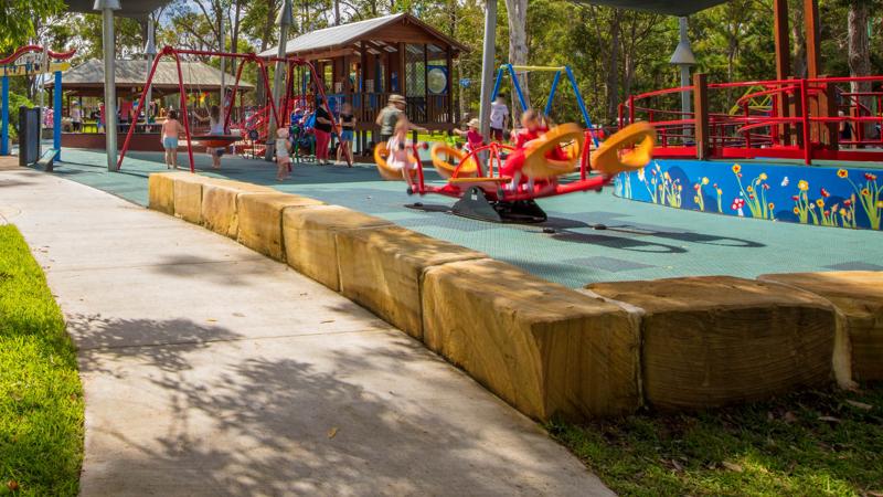
Timber (not preferred)
Timber is not a Council preferred wall material due to ongoing maintenance cost and vulnerability to white ants and weathering.
- Advice is to be sought from a suitably qualified engineer on the most suitable type of retaining wall for specific site conditions.
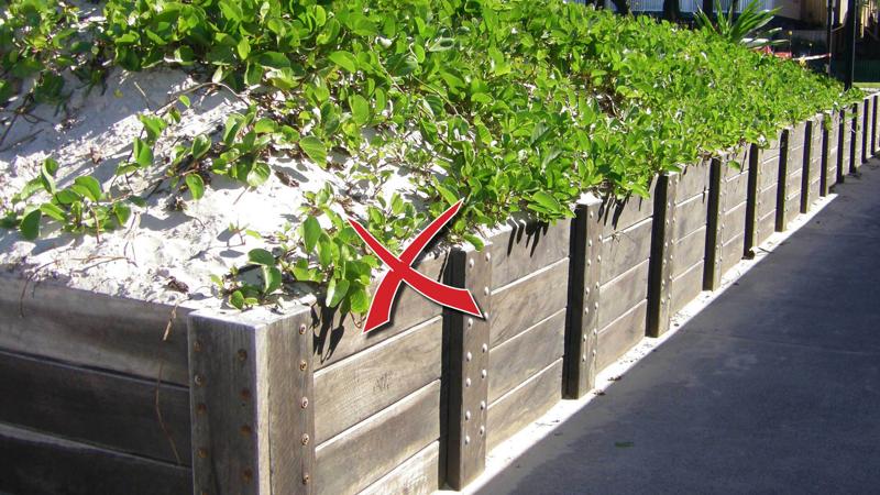
Timber
Walls for signage
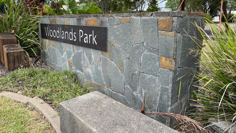
Entry statement/signage walls
Construction and materials are to meet the following:
- Walls over 1.0 m high to be designed by a suitably qualified engineer
- Signage walls create a backdrop against which lettering is displayed, such as at a community sporting precinct, or an entry statement to a suburb.
- Most materials are suitable for signage walls however select robust materials and finishes which minimise cost implications incurred with ongoing maintenance regimes.
- Apply place-making principles to ensure the essence of the area is captured and represented.
- Entry walls with electricals housed inside (i.e. for lighting), must provide maintenance access for in-situ repairs
- Spectral reflection (the reflection of a beam of light from a mirror like surface) should be considered when selecting materials such as polished stainless steel for lettering on any signage wall which can to be viewed from the road. See Manual of Uniform traffic Control Devices (MUTCD).
- Timber is NOT a Council preferred material due to ongoing maintenance cost and vulnerability to white ants and weathering.
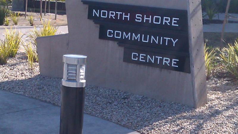
Community centre signage wall

Entry statement wall
This component is currently in development