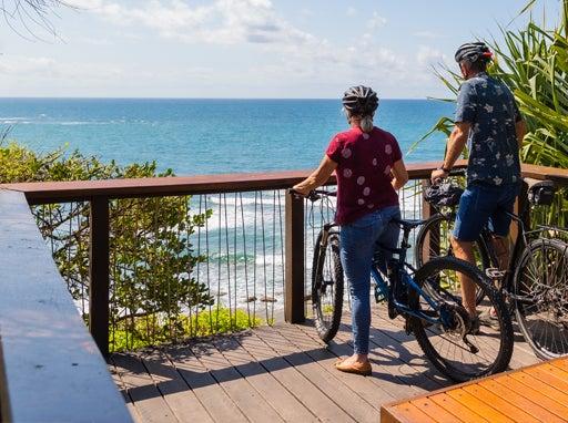
Boardwalks and viewing platforms
Design
Requirements for the design, manufacture and installation of embellishments
Good design
See the following corporate documents to identify relevant project design requirements:
Sunshine Coast Planning Scheme regulates the way land, buildings and structures are used and developed on the Sunshine Coast.

Sunshine Coast Design contains 10 design principles that guide good project planning and design outcomes, that are appropriate for the Sunshine Coast.
The LIM provides further overarching design advice, refer:
- Introduction and Design Principles - e.g. sustainability, CPTED, accessibility
- Preliminaries - environmental management, tree sensitive design and site set up.
Embellishment requirements
- Universal access.
- Comfortable and suitable for the average person.
- See 'Positioning' and 'Equal access' sections for the corresponding LIM category.
- Made from materials that will be durable and can be suitably protected from exterior elements, such as salt spray and UV exposure.
- Robust and sturdy to withstand constant public use and be resistant to vandalism.
- Fixings are to be 316 marine grade stainless steel (unless otherwise stated).
- Tamper proof fixings should be used
- Graffiti protection coatings applied (where applicable)
- Fire retardant (where applicable).
- Warranties should be as listed below.
- Easily repairable or replaceable.
- Sourced locally and use standard fittings.
- Reputable suppliers should be used who keep a supply of stock parts on hand for the life of the product.
- Use sustainable materials, although sustainability needs to be considered over the lifetime of the embellishment.
- Install on paved, concrete or other hard surfaces (where applicable).
- Manufactured to engineering specifications (where applicable).
- See the 'Standards' section for the corresponding LIM category.
Warranty and asset life
Product/embellishment | Warranty (minimum) | Asset life (typical useful life) |
Recycled plastic | 10 years | 25 years 2 |
Timber | N/A | 20-30 years 2 |
Stainless steel | Varies | 25 years 2 |
Concrete | Varies | 25 years 2 |
Fibre reinforced plastic | Varies | Not available |
Source 2: Sunshine Coast Council Asset Management Plan 2017/18-2022/23 – Parks and Gardens (figure based on current data, subject to change).
Boardwalks and viewing platforms
Once the location of the boardwalks and viewing platforms has been decided, based on the Environment and Liveability Strategy (ELS) and Recreation Parks Plan (RPP) guidance, consider the appropriate embellishment level to suit the selected site.
Overarching design considerations:
- All open spaces should include universal access (e.g. provide ramped access)
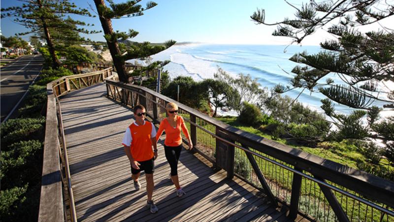
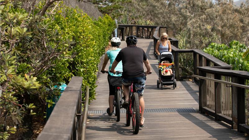
- Boardwalks and viewing platforms provide all weather access to an area or across an area which may otherwise be inaccessible, particularly for people with a disability. They comprise a horizontal decked walkway or platform on pier or piled footings, or on-ground.
- This document provides general guidelines only and does not cover comprehensive specific technical detail about constructing boardwalks and viewing platforms.
- Design must be certified by a Registered Professional Engineer Queensland (RPEQ).
Design of boardwalk and viewing platforms
Boardwalks and viewing platforms should be designed to balance durability, accessibility, and environmental protection in coastal and sensitive areas.
The following should be considered when designing boardwalks and viewing platforms:
- Consider coastal/hydraulic processes.
- Geotechnical investigation is required to determine foundation conditions for the design of supports.
- Materials selected must be suitable for use in low lying areas that have the potential to become waterlogged. Structures should be above extreme tides, storm surge and flood levels (where possible).
- Where a boardwalk is subject to tidal inundation, design the boardwalk so that it dries as soon as possible after getting wet.
- Consider composite materials FRP (fibre reinforced plastic) at locations such as beach accesses and wetlands.
- Design the structure so that it is self-cleaning without fixed elements that block the flow of water and leaf litter.
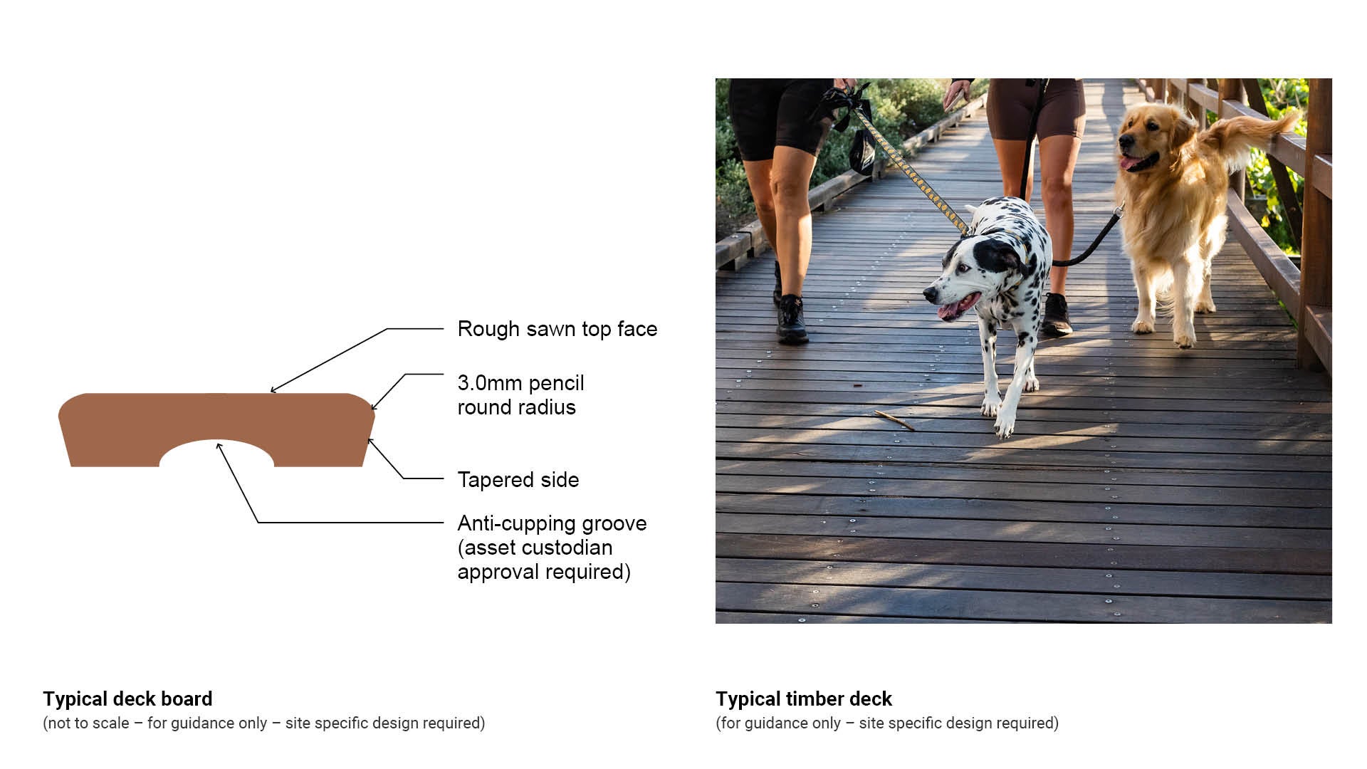
- Timber boardwalks and viewing platforms should have a rough sawn face to provide sufficient slip resistance.
- Consider that aluminium, stainless steel and recycled materials may be hot underfoot.
Coastal management district
The environment must be considered and protected before any development or construction is undertaken.
Boardwalk and viewing platforms near beaches should be planned and designed to protect the surrounding environment whilst providing a safe path of travel for the public. Consider sand blow. An appropriate boardwalk treatment will minimise negative impacts on the coastal environment.
Environmental/tree protection
Boardwalks limit pedestrian activity and protect sensitive areas and environments.
Where an area of tree root conflict exists, a boardwalk section over the affected area may be appropriate.
- Protect trees by elevating a boardwalk over existing tree root systems to:
- minimise excavation and site disturbance
- minimise compaction to prevent de-oxygenation of soils
- retain water and nutrient availability for trees
- room for continued growth of tree roots without risk of damage to infrastructure
- preservation of soil structure
- protect structural root systems.
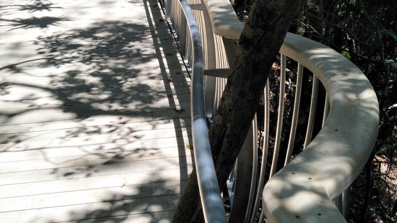
- Use a flexible construction to allow the design to work around trees and tree roots.
- See LIM Tree sensitive design (existing and new trees) for further guidance.
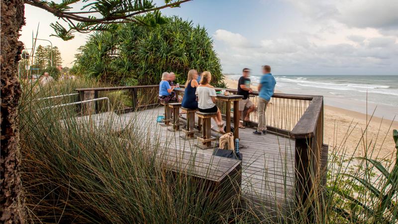
Recreational
- Appraise the opportunity for a boardwalk or viewing platform to provide equal access walking/cycling/viewing appreciation of the natural environment at the following locations:
- nature trails
- watercourses
- wetlands
- sensitive coastal environments
- flora and fauna.
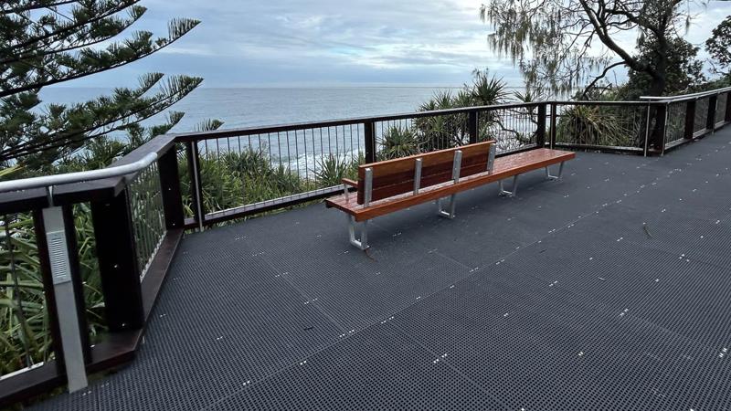
- Select appropriate locations for viewing platforms to provide rest and the opportunity to showcase natural areas.
- Install seats which are off the boardwalk path of travel or at the edges of wider boardwalks. Select intervals to provide rest opportunities for a wide range of abilities (recommend 60 m apart for older people).
Designing for loads
Designing for loads requires careful consideration of structural integrity, safety standards, and anticipated usage to ensure the boardwalk and platforms remain durable and compliant.
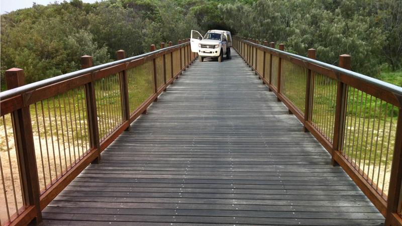
Light vehicles/pedestrians/cyclists
Boardwalks and viewing platforms must be designed to provide access for light vehicles to undertake maintenance and at site specific locations for emergency vehicles.
Design must comply with all relevant Australian Standards, codes and design guidelines.
- Live load is the dynamic load imposed by vehicles, pedestrian and other users that can change over time. Live loads are variable as they depend on usage and capacity.
- Point load is an established load located at a single point on a supporting structure.
- Dead load is the self-weight of the structure by itself (excluding users), resting on the abutments and piers.
- Comply with Safety in Design requirements.
- Apply the design criteria producing the safest possible results that also meet Work Health and Safety requirements.
Boardwalks
Boardwalk members are to be designed for strength to support a combinations of factored loads and forces.
- Geotechnical investigation is necessary to determine the foundation conditions for the design of footing supports to withstand anticipated loadings.
- Consider boardwalks to be continuous viewing platforms for design loading purposes.
- Consider user groups such as:
- pedestrians
- cyclists
- motorcycles
- quad bikes
- golf buggies
- incidental vehicle access
- maintenance vehicles/emergency vehicles.
- Consider the likelihood of crowd loading on any section of a boardwalk.
- Boardwalks must be designed so they do not impose lateral loads on adjacent structures such as existing seawalls.
- Boardwalks may be required to conform to the BCA (Building Code of Australia) where they form part of access to, or between buildings, or to Austroads Bridge code where they form an extension to a bridge.
- Bridges are designed to the requirements of AS 5100 Bridge design with considerations of the Austroads Guide to Bridge Technology.
Viewing platforms and fishing platforms
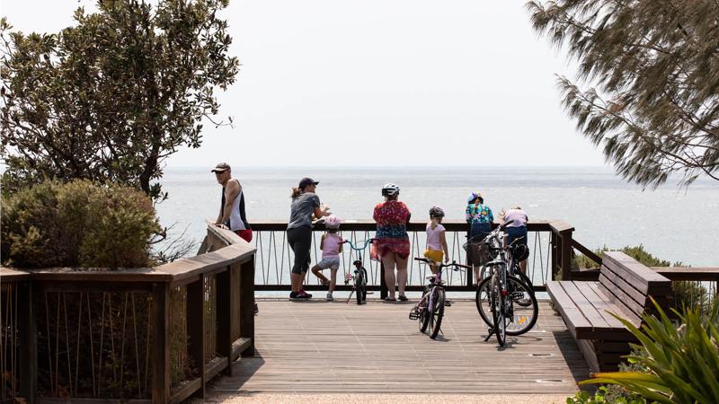
Design for viewing platforms must be engineered as per boardwalks including consideration to:
- Suit variables and attributes of the proposed location.
- Limit pedestrian interaction on sensitive environments.
- Consider the likelihood of crowd loading such as photography of a large group, and crowd panic behaviour.
- About 1.35 kN load equates to a walker with a full backpack (British Code).
- Dedicated public fishing platforms are constructed at popular fishing locations, particularly for inexperienced and family anglers and those without boats. Where possible they should include handrails with provision for resting fishing rods.
- Fishing associated embellishments should be located nearby, such as:
- taps
- fish cleaning tables
- general and recycle waste bins
- tackle disposal bins.
Glossary of structural components
This section details the components that make up boardwalks and viewing platforms.
See Figure 1: Glossary of structural components for a summary.
Figure 1: Glossary of structural components
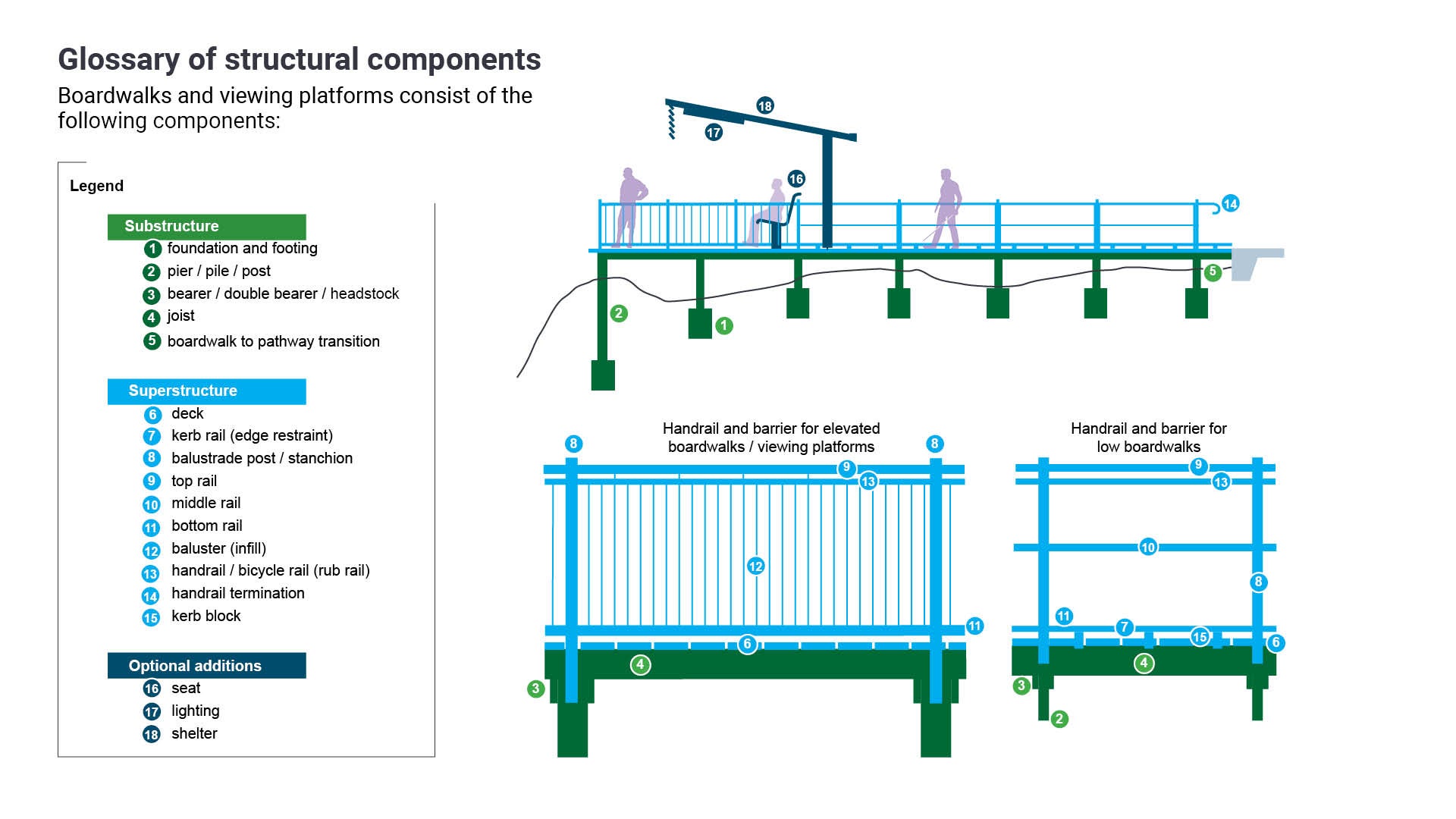
Table 1: Glossary of structural components
Components level | Structural components | Refer Figure 1 (above) |
 | Substructure
| See Figure 1: Glossary of structural components demonstrates the location of each structural component. |
 | Superstructure
| See Figure 1: Glossary of structural components demonstrates the location of each structural component. |
 | Optional additions
| See Figure 1: Glossary of structural components demonstrates the location of each structural component. |
Substructure (supporting structure)
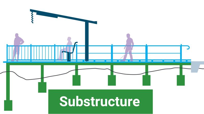
The substructure refers to all the components that support and stabilise the walking surface (the superstructure). It is the foundation system that transfers loads from the deck to the ground.
Foundation and footings
Foundations describe various types of support to a structure such as:
- Strip footings
- Screw piles
- Driven piles
- Bored piers.
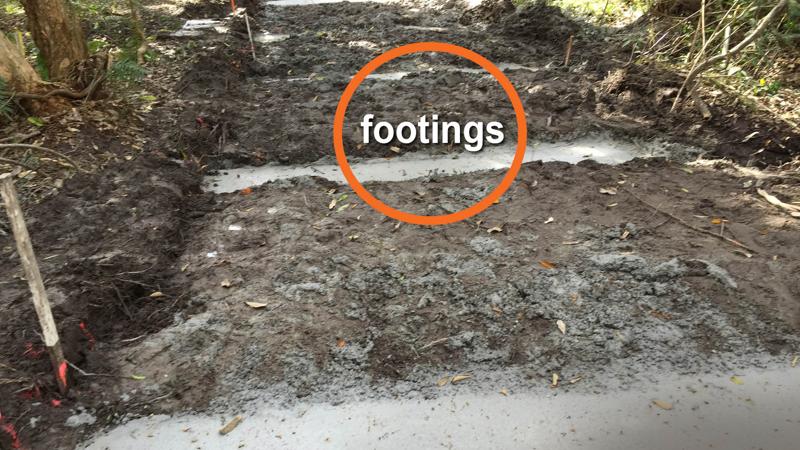
Footings are a below ground base which distributes the load and forces of the structure over a wider area of the natural rock or sub-soil. See Figure 4: Example - foundation/pad/strip footings.
Footings must be rigid enough to protect the boardwalk from foundation movement.
- If the local surface is capable of supporting the structural loads, pad footings or strip footings may be used.
- Pad footings comprise a pad used to support a pier or post.
- Continuous footings take the form of a continuous linear slab or strip that supports uniformly distributed loads.
- RPEQ certification is required for any structural elements.
Pier/pile/posts
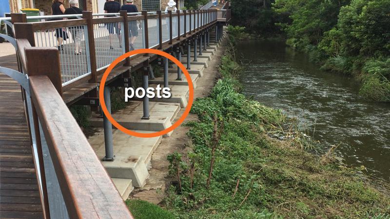
A pier is a post like vertical foundation member which secures the structure and transfers structural loads to the foundations.
- If the local ground/subgrade cannot support the structure, piles or piers are used to transmit the load to a foundation at a greater depth that can support the loads.
- Screw piles are mechanically screwed into the soil and can be used as stumps for a raised platform.
- Piles must be capable of resisting uplift loads (buoyancy, wave loads etc.) applied to the boardwalk structure, where required.
- Consider tolerances when designing elements to be connected to the boardwalk at a future time such as lighting, balustrade, seats, shelters, and fauna hides.
- Set out posts, bearers and joists to allow predetermined lengths to be used.
- RPEQ certification is required for the design and installation of boardwalk footings and piles.
See Figure 2: Typical pier footing detail.
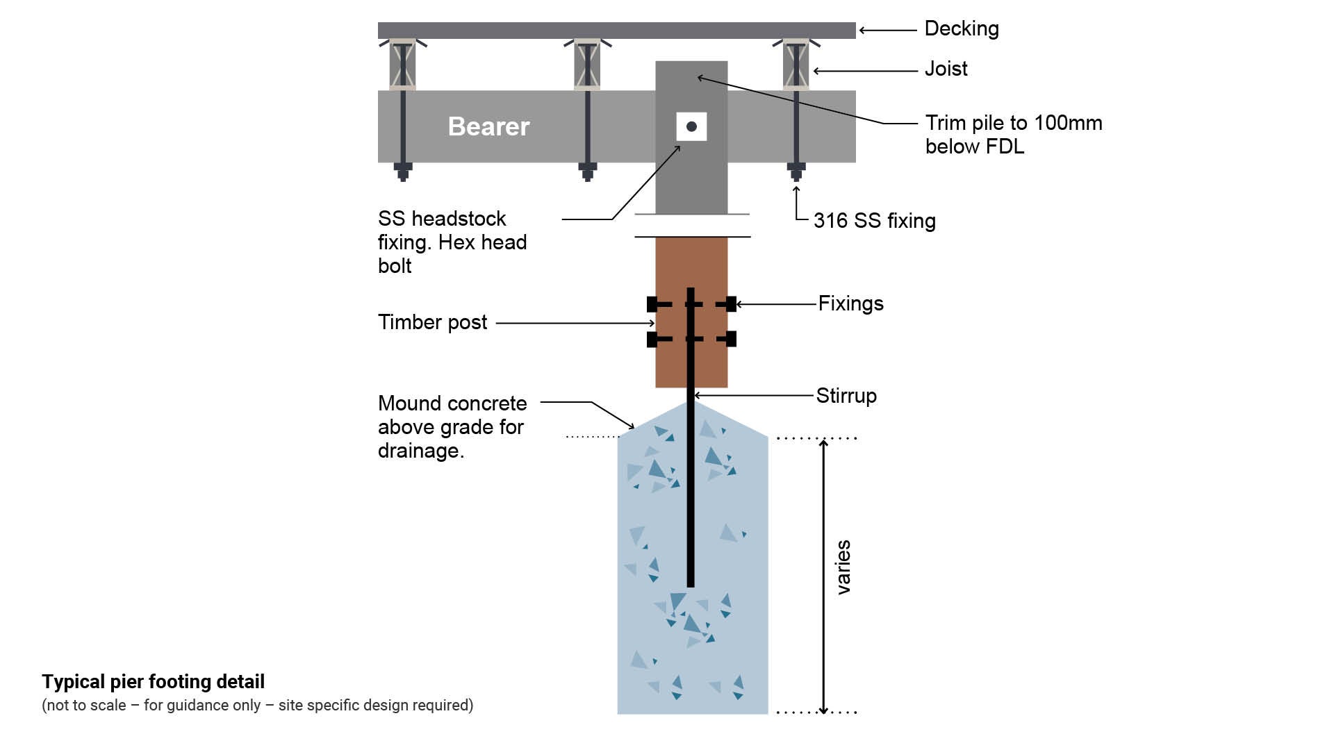
Figure 2: Typical pier footing detail
Bearer/double bearer/headstock
A bearer is a horizontal, load supporting structural member.
- A timber, concrete, composite material, stainless steel, aluminium or HDG (hot dipped galvanised) steel bearer is attached to the posts that support the deck.
- Bearer size and fixing of the bearer to the post, is important for the durability of the structure.
- Minimum 75 mm wide hardwood is preferred for good bolting practice. Refer engineer’s specifications.
- Use 3 M tape (or equivalent), or bitumen filler in checks
- Use malthoid strip (or approved equivalent) on cuts
- Select horizontal versus vertical bolting where possible.
- Twin bearers (headstocks) work well for boardwalks taking heavier loads, and facilitate:
- joist lapping
- predetermined joist and deck lengths.
- In heavier decks and boardwalks stainless steel angles with horizontal bolting is preferred.
Joist
Joist is a horizontal load supporting structural member which supports a floor/deck timbers.
- Joists are the members attached across the bearers to which decking boards are attached.
- Design the boardwalk for predetermined lengths of joists to save material and allow predictable fixing locations for decking.
- Lapping of joists other than edge joists allows predetermined lengths of joists.
- Joist material can be timber, metal, concrete or composite materials.
- When using timber joists, select minimum 75 mm width hardwood for external exposed to weather decks and boardwalks, to prevent splitting at deck screws (50 mm wide is insufficient).
- Select royal species only such as Ironbark, Spotted Gum, Tallowood and Satinay.
- Use aluminium and bitumen tape, malthoid strip (or approved equivalent) on top of timber joists to prevent water entry into the top of the joist.
- Stagger fixings into joist to avoid splitting the joist.
See Figure 3: Typical double bearer/headstock pile connection.
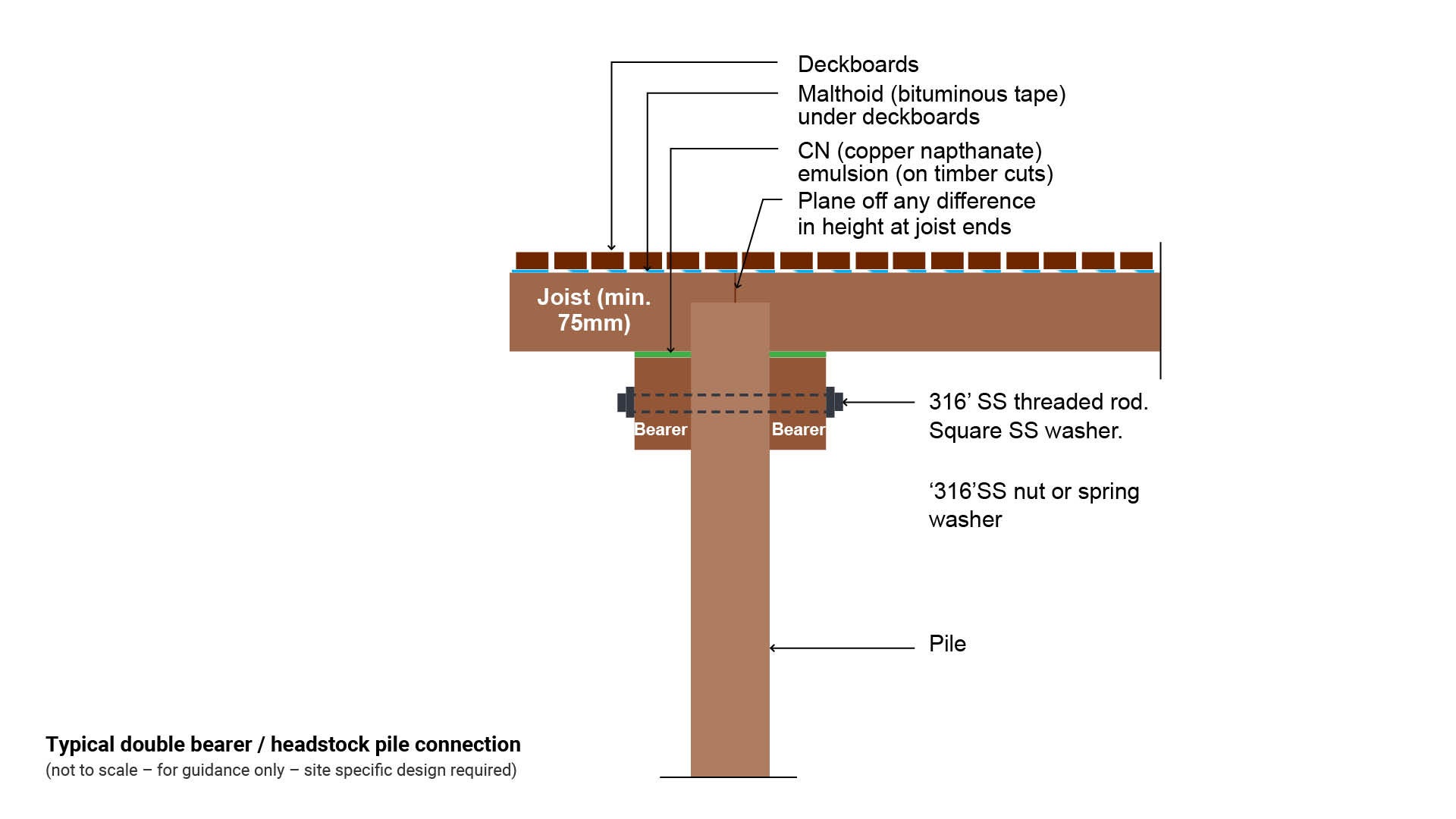
Figure 3: Typical double bearer/headstock pile connection
Boardwalk to pathway transition (timber to concrete)
Where a timber boardwalk transitions to a concrete walkway/pathway, the discontinuity is prone to vertical displacement.
Timber boardwalk to concrete transitions must be designed to control differential movement once timber shrinkage occurs.
Risk of a vertical or horizontal displacement resulting in a pedestrian trip hazard or cyclist hazard may be reduced (where possible) by providing the following:
- Threaded rods with nuts to mechanically adjust the height of a boardwalk.
- Physical interlocking such as a stainless steel tie bar.
See Figure 4: Typical timber to concrete pathway transition and Alternative timber to concrete pathway transitions.
Figure 4: Typical timber to concrete pathway transition and Alternative timber to concrete pathway transitions
Superstructure (upper part of the structure)
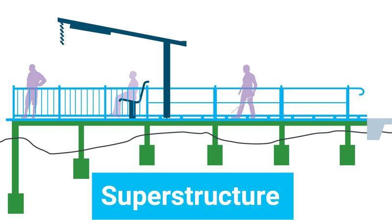
The superstructure of a boardwalk refers to all the components above the substructure that form the visible, functional walking surface and any associated features.
Deck
Decking is the material forming a horizontal platform for walking/cycling. Decking boards span the area over the joists and form the deck floor.
- Materials include treated timber or naturally durable timber, FRP (fibre reinforced plastic), concrete, aluminium, recycled plastic. Wood plastic composite is not preferred.
- Clear width for a boardwalk deck between edge restraints or handrail and balustrade varies.
See LIM Paths, trails, tracks for further guidance
Fibre reinforced plastic (FRP) deck, aluminium deck, concrete deck
Refer manufacturer/supplier for details and installation method.
Timber
Timber decking should be Royal Species, a collection of timbers with proven natural durability and strength. Select Ironbark, Spotted Gum, Tallowood and Satinay, rather then strength F11, F14, F17. No Blackbutt.
- Where vehicle movement or parking is expected, select thicker boards such as 120 x 35 mm or 145 x 45 mm with natural sawn face and arrised edges. These can be rough sanded if required to improve slip resistance.
- Decking boards are to have 3.0 mm arris or pencil round to top edges, and tapered sides.
- Boards are to have a clear face - no longitudinal or radial shelling, knots or surface gum veins.
- Deck boards are to be laid heart down to prevent cupping. Do not lay reeded deck boards face up as they will rot quickly.
- Treat all cut ends with CN emulsion.
- Asset custodian to determine if anti-cupping grooves are required.
See Figure 5: Typical deck board.
Figure 5: Typical deck board and Typical timber deck
Timber deck construction
The deck laying gap is the calculated allowance between decking boards before they are fixed to joists. The laying gap considers the anticipated shrinkage of a particular timber species as well as the proposed deck board dimension, together with the requirements of Standards and guidelines. Decking gaps allow water and debris to shed off the deck surface.
- Example to determine deck timber laying gap:
- Unseasoned Spotted Gum or Ironbark decking timber up to 145 mm wide, expected shrinkage is 6%. Approximately 9.0 mm (across the board).
- Deduct the expected shrinkage from the target gap to calculate the laying gap.
- AS 1428 Design for access and mobility standards (Set), allow a maximum 10 mm gap in decking boards (after shrinkage).
- Select seasoned timber for a 3.0 mm target gap (where high heels are expected). DO NOT use Blackbutt as it undergoes up to 12% shrinkage.
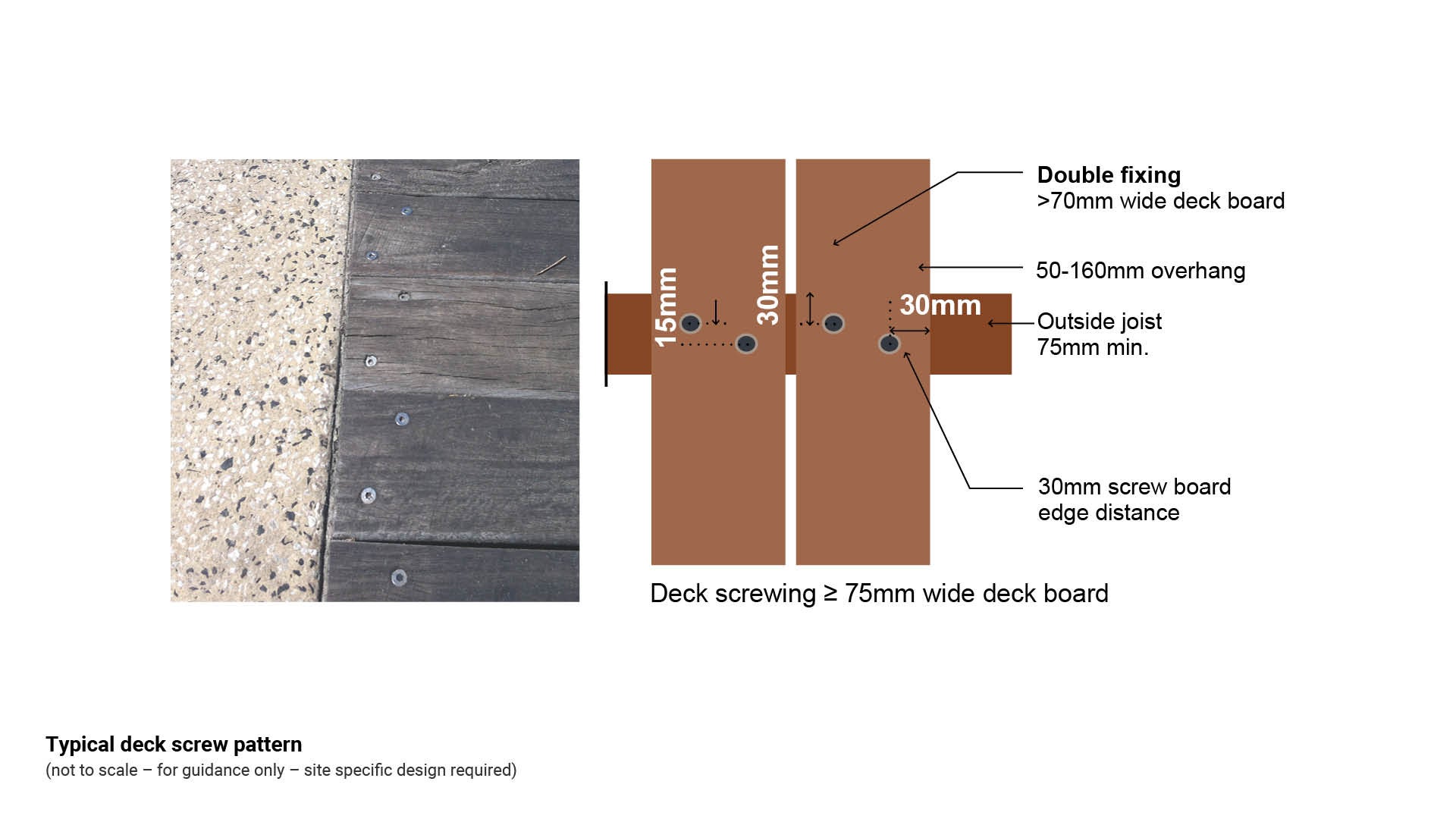
- Screw decking boards to joist with a staggered pattern and pre-drill joist to prevent splitting of joists.
- Ensure the deck screwing pattern is detailed in full on design drawings.
See the following:
- Figure 6: Typical deck construction (45 x 145 mm deck timber where vehicles are anticipated)
- Figure 7: Typical deck screw pattern.
Figure 6: Typical deck construction (45 x 145 mm deck timber where vehicles are anticipated)
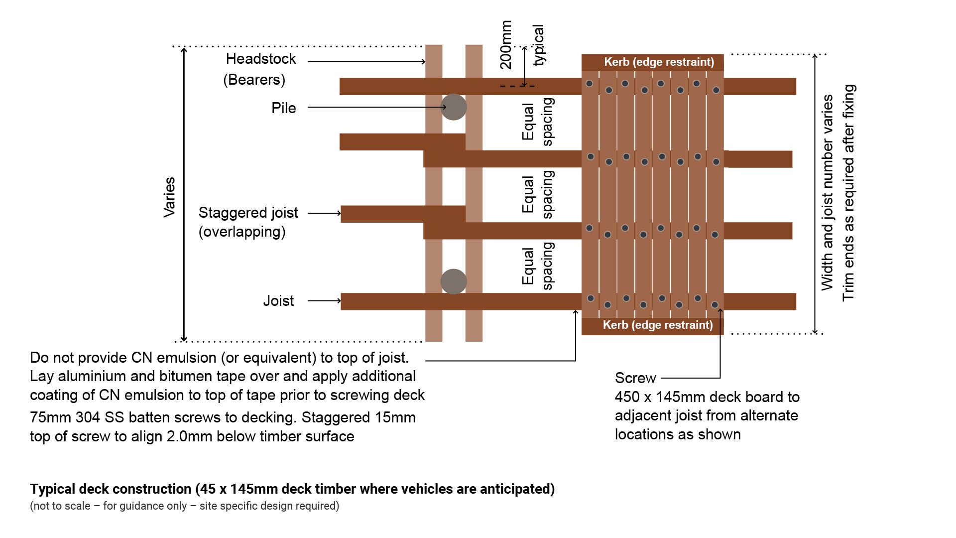
Figure 7: Typical deck screw pattern
Kerb (edge restraint)
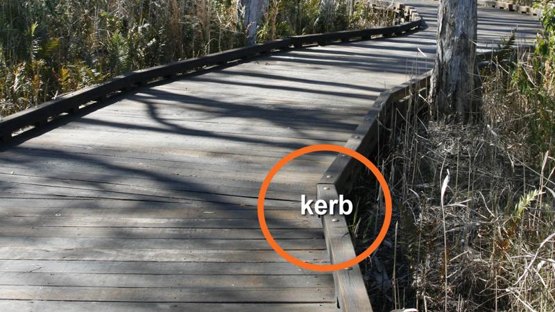
A kerb is a raised side barrier that defines the edges of a boardwalk or viewing platform.
- Kerbs provide the following benefits:
- delineation for people who are blind and people with low vision
- restrains bicycles, prams and wheeled mobility devices from running off the edges of a boardwalk or deck
- prevents wheeled devices from becoming bogged in soft ground, sand or garden beds.
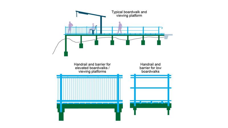
Balustrade posts/stanchions
Vertical members attached to the substructure to provide support for balustrades, handrails and baluster (infill) material.
Rails
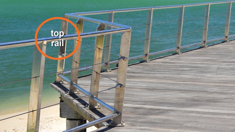
Top rail
A horizontal member attached near the top of balustrade posts to provide for attachment of handrail and structural integrity for infill material.
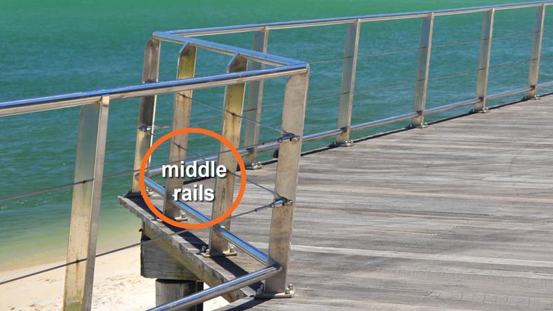
Middle rails
A horizontal member attached near the middle of posts to provide structural integrity and to provide added protection from risk of falls.
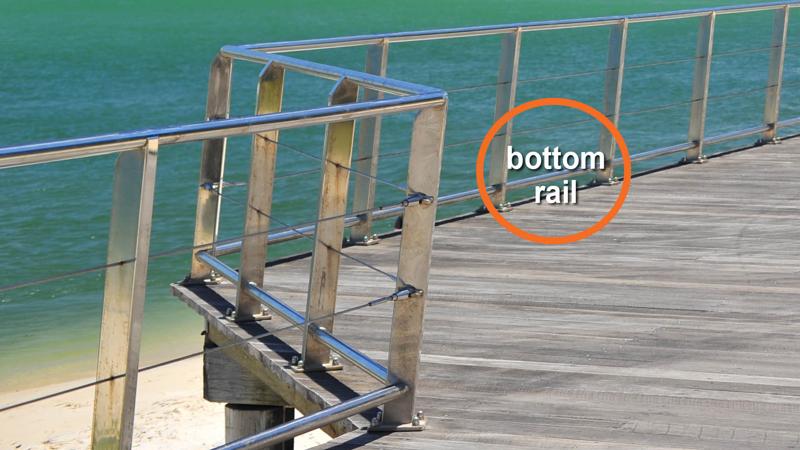
Bottom rail
A horizontal member attached near the bottom of posts, near the deck, to provide structural integrity to baluster material. Can act as a kerb rail.
Baluster (infill)
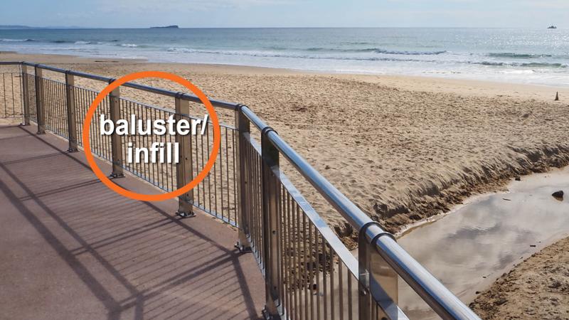
Baluster infill is a barrier which may consist of a series of vertical balusters. Baluster may include vertical or horizontal posts.
- Baluster are intended to protect users from hazards and falls. The design depends on:
- the height of the boardwalk/viewing platform above the ground or water.
- the material immediately below the boardwalk.
- anticipated risk of falls
- safety/historical data.
See LIM Handrail and balustrades for further guidance.
Handrail/bicycle rail (rub rail)
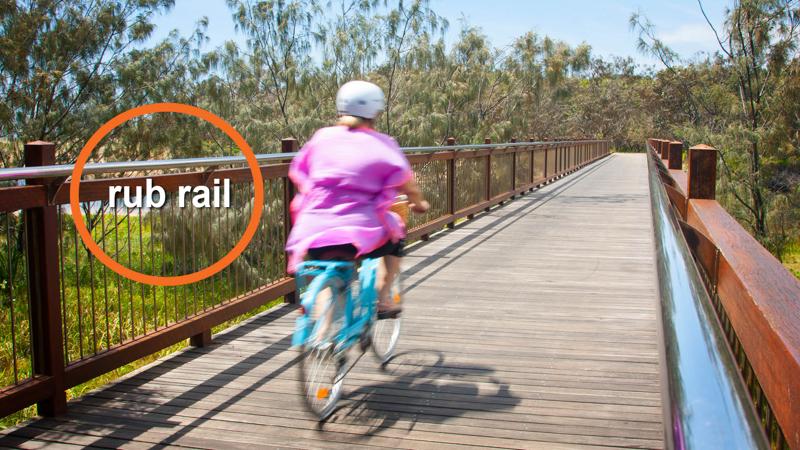
Handrail is a rail fixed to posts or a wall for people to hold on to for support or direction. The design must comply with AS 1428 Design for access and mobility. They also:
- Prevents falls
- Provide rest opportunities
- Confine users to the boardwalk
- Assist older people and people with a disability
- Guide people with low vision.
Timber handrail/bicycle rail must shed water.
Bicycle rail is a high rail offset from a barrier for a rest rail and for cyclist safety (see Austroads Guidelines).
See LIM Handrails and balustrades for further guidance.
Kerb blocks
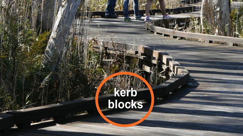
Kerb blocks are raised blocks fixed to the decking to elevate a kerb rail. Kerb blocks provide:
- Support to fix a kerb onto low/on ground boardwalks.
- Cleansing drainage flow off a deck.
- Removal of leaf litter from a deck surface.
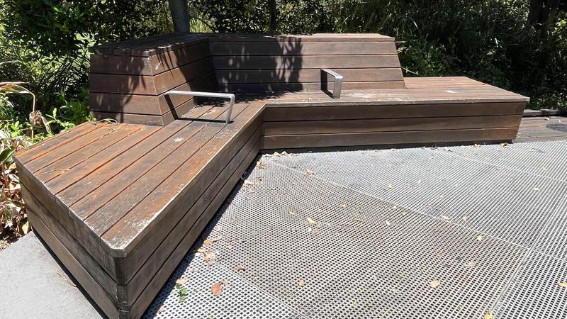
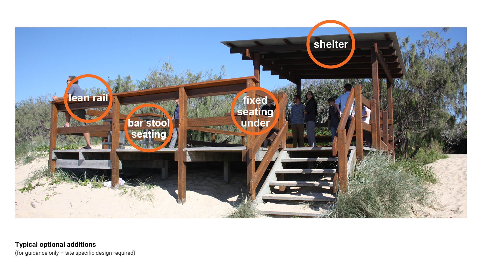
Optional additions (ancillary embellishments)
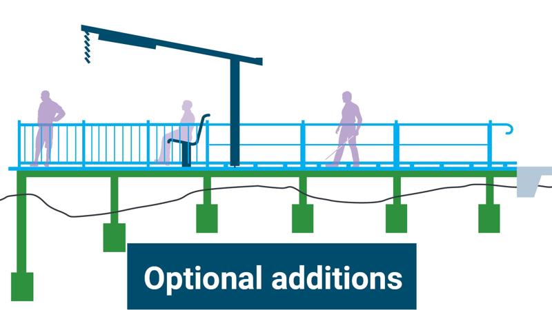
Optional additions (ancillary embellishments) are integrated into the boardwalk and/or viewing platform to provide functional enhancements and improve overall user experience. See Figure 8: Typical optional additions for an example.
Seats
Seats should be included at regular intervals (60 m minimum spacing recommended) along, or alongside a boardwalk and at points of interest (where possible).
- Seating at viewing decks and hides provides an opportunity for rest and to enjoy the scenery.
See LIM Seats for further guidance.
Lighting
Provides safety and extended use of the facility.
- Good lighting design contributes interest and enhances night time experience and activation.
- Design turtle safe lighting at beach side locations and where lighting may impact turtle breeding sites.
See LIM Electrical for further guidance.
Shelter
Provides shade protection for enjoyment of a boardwalk/viewing platform.
See LIM Shelters for further guidance:
Figure 8: Typical optional additions
Construction sequence examples
This section provides best practise examples of construction sequences of boardwalks and or viewing platforms using preferred materials; timber, pre-cast concrete and fibre reinforced plastic (FRP).
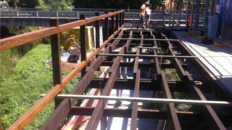
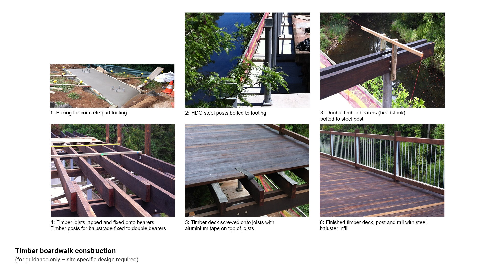
Timber boardwalk construction sequence
Timber boardwalks are typically selected for ease of materials supply and natural appearance for wetlands or environmentally sensitive areas.
Steel posts for the boardwalk are constructed, elevating it above the ground below, then the superstructure is constructed in sections. See Figure 9: Timber boardwalk construction.
Figure 9: Timber boardwalk construction
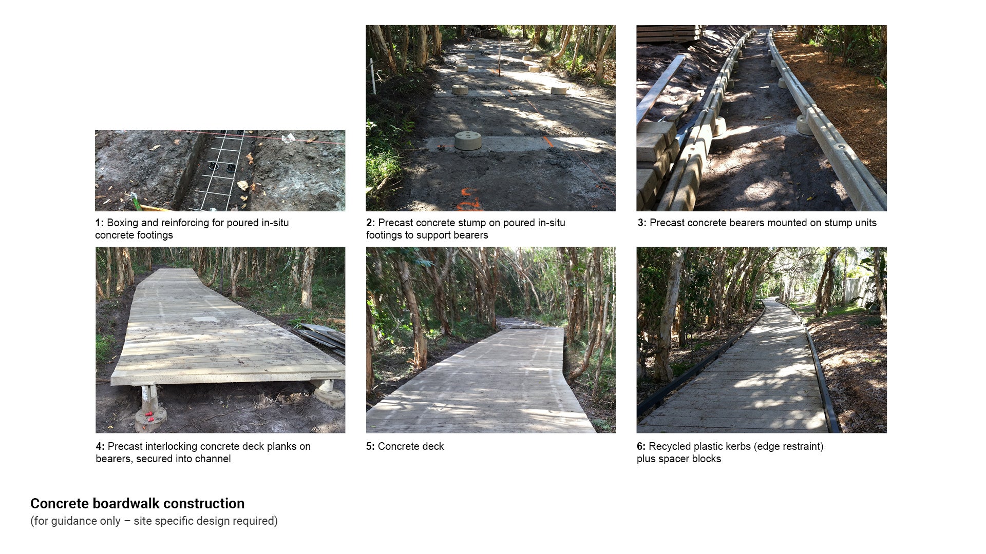
Pre-cast concrete boardwalk construction sequence
To preserve and protect sensitive areas and where ground conditions are suitable, concrete boardwalks can be designed for “top down construction”. Boardwalk components are designed to support construction equipment loads. Boardwalk beams and treads are installed from equipment operating on top of previously installed treads and beams. See Figure 10: Concrete boardwalk construction.
Figure 10: Concrete boardwalk construction
Timber decking on fibre reinforced plastic (FRP) and concrete construction sequence
Timber boardwalks superstructure elements are selected for ease of materials supply and natural appearance.
Fibre reinforced plastic (FRP) substructure is constructed, above ground level on steel tube core filled epoxy coated piers or set in concrete footings. The timber superstructure is constructed next. See Figure 11: Timber/FRP boardwalk.
Figure 11: Timber/FRP boardwalk

This component is currently in development