Landscape drainage

Design
Requirements for the design, manufacture and installation of embellishments
Good design
See the following corporate documents to identify relevant project design requirements:
Sunshine Coast Planning Scheme regulates the way land, buildings and structures are used and developed on the Sunshine Coast.

Sunshine Coast Design contains 10 design principles that guide good project planning and design outcomes, that are appropriate for the Sunshine Coast.
The LIM provides further overarching design advice, refer:
- Introduction and Design Principles - e.g. sustainability, CPTED, accessibility
- Preliminaries - environmental management, tree sensitive design and site set up.
Embellishment requirements
- Universal access.
- Comfortable and suitable for the average person.
- See 'Positioning' and 'Equal access' sections for the corresponding LIM category.
- Made from materials that will be durable and can be suitably protected from exterior elements, such as salt spray and UV exposure.
- Robust and sturdy to withstand constant public use and be resistant to vandalism.
- Fixings are to be 316 marine grade stainless steel (unless otherwise stated).
- Tamper proof fixings should be used
- Graffiti protection coatings applied (where applicable)
- Fire retardant (where applicable).
- Warranties should be as listed below.
- Easily repairable or replaceable.
- Sourced locally and use standard fittings.
- Reputable suppliers should be used who keep a supply of stock parts on hand for the life of the product.
- Use sustainable materials, although sustainability needs to be considered over the lifetime of the embellishment.
- Install on paved, concrete or other hard surfaces (where applicable).
- Manufactured to engineering specifications (where applicable).
- See the 'Standards' section for the corresponding LIM category.
Warranty and asset life
Product/embellishment | Warranty (minimum) | Asset life (typical useful life) |
Piped network - AC pipe | 10 years | 70 years 2 |
Piped network - concrete pipe | 10 years | 70 years 2 |
Piped network - UPVC | 25 years | 70 years 2 |
Piped network - HDPE | 50 years | 70 years 2 |
Pits - inlets, outlets, endwalls | 10 years | 50 years 2 |
Culverts - box and pipe | 10 years | 70 years 2 |
Open drain - concrete/rock | 10 years | 70 years 2 |
Open drain - earth and vegetated | N/A | 25 years 2 |
Open drain - canals, revetment walls | N/A | 50 years 2 |
Water quality - engineered natural systems | N/A | 25 years 2 |
Water quality - concrete (e.g. GPT) | 5 years | 50 years 2 |
Floodway | 10 years | 50 years 2 |
Source 2: Sunshine Coast Council Asset Management Plan 2017/18-2022/23 – Stormwater (figure based on current data, subject to change).
Landscape drainage
Once the location of the landscape drainage has been decided, based on the Environment and Liveability Strategy (ELS) and Recreation Parks Plan (RPP) guidance, consider the appropriate embellishment level to suit the selected site.
Overarching design considerations:
- Design in accordance with IPWEA (Institute of Public Work Engineering Australia) standard drawings and QUDM (Queensland Urban Drainage Manual).
- Design to the site conditions to direct and channel the overland flow.
- Accommodate all roof and surface water runoff, originating in the site or flowing through the site.
- Existing overland flow paths are to be preserved.
- Overland flow paths should be located in road reserves, parks, or other council controlled land, and should not traverse private property unless an easement has been arranged.
- Location of surface and subsurface drainage should be clearly indicated on design drawings, including the nominal depth and width.
- Location of outlets and cleanouts should also be indicated on design drawings.
See Table 1: Landscape drainage recommendations for further guidance.
Note: LIM Landscape drainage requires professional interpretation and judgement to ensure drainage measures are appropriately adapted for local conditions and local data.
Design of landscape drainage
Landscape drainage is designed to provide water free surfaces for safe park and open space activities, in average weather conditions. The design should prevent water-logging of parks and dangerous water build-up in storm events.
Landscape drainage may be a buried or a surface solution, or a combination of both. Prefabricated culverts and piped systems are made from concrete, steel, aluminium, high density polyvinyl chloride (PVC) and other synthetic materials. Products such as rock and gravel provide a natural surface drainage look.
Safety
- Design to handle peak loads as specified by an accredited engineer.
- Urban waterways and stormwater drainage systems can represent a significant safety risk during storms and times of flood. The design of drainage systems which require safety fencing is discouraged and should only be used if required to meet the risk, in accordance with the QUDM.
Drainage products
- Product design for drainage components is to be as per Australian Standards for concrete/steel/plastics and composite materials.
- Products should be designed for use in stormwater drainage applications and be suitable for buried applications.
- Screens for inlets are available in cast iron, ductile iron (more flexible than cast iron), mild steel (subject to rust unless galvanised) and stainless steel.
- Avoid using metal grates and pit lids where bare feet may come into contact with heated surfaces such as within pathways.
- Drainage surface products must comply with Australian Standards for slip resistance.
- Select products appropriate to location and environmental conditions.
Drainage types
The recommended drainage types include sub-surface drainage, field inlet and overflow gully, grated trench drain, open flow channel (swales), and culvert with overpass. These systems are essential for managing water flow and ensuring effective access across various landscapes.
Table 1: Landscape drainage recommendations
Drainage type | Recommended use |
Sub-surface (or sub-soil) drainage |
|
Field inlet and overflow gully |
|
Grated trench drain |
|
Open flow channel (swales) |
|
Culvert and pipe culvert with overpass |
|
Sub-surface (or sub-soil) drainage system
- Best practice to reduce drainage volume, remove excess water from the soil profile, and prevent water logging.
- IPWEA standard drawing RS-140 Subsoil Drains Details and Locations and RS-142 Subsoil Drains Access Points.
Sub-soil drain (perforated pipe)
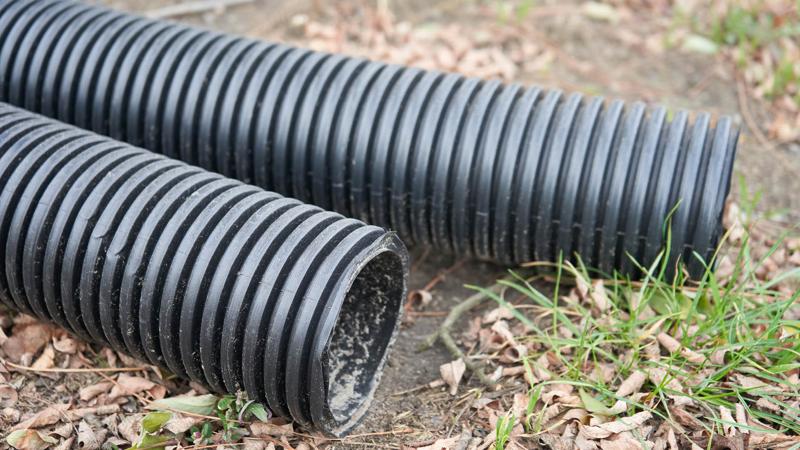
- Heavy duty PVC corrugated slotted pipe suitable for buried applications.
- Geofabric may be used to line trenches to prevent small diameter rock and sand entering the pipe.
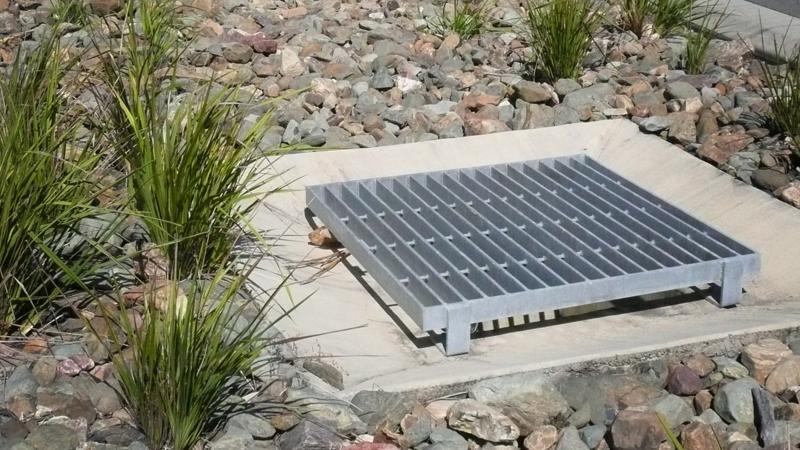
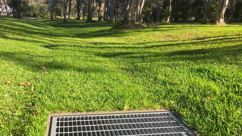
Field inlets and overflow gully
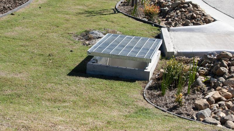
- For inlets within or outlets to an overland flow path, the design should be in accordance with QUDM.
- 50% blockage factor for a screen dome and elevated horizontal grate. 80% blockage factor for flush mounted grates. Details can be found in QUDM.
- Grate size and design to be specified by a suitably qualified engineer, with regard to hydraulic requirements.
- An abrasive surface treatment can be applied to a pre-galvanised grate to create a slip resistant finish. Select slip resistant grates such as SlipNOT (or equivalent) where the grate is traversed by pedestrians.
- Designed with positive fall to stormwater outlets.
- A grated cover is required to minimise risk of children accessing drains.
- Avoid using metal grates and pit lids where bare feet may come into contact with heated grate/lid materials, or apply a heat resistant, pedestrian grade anti-slip coating.
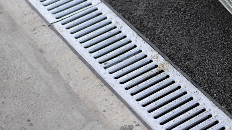
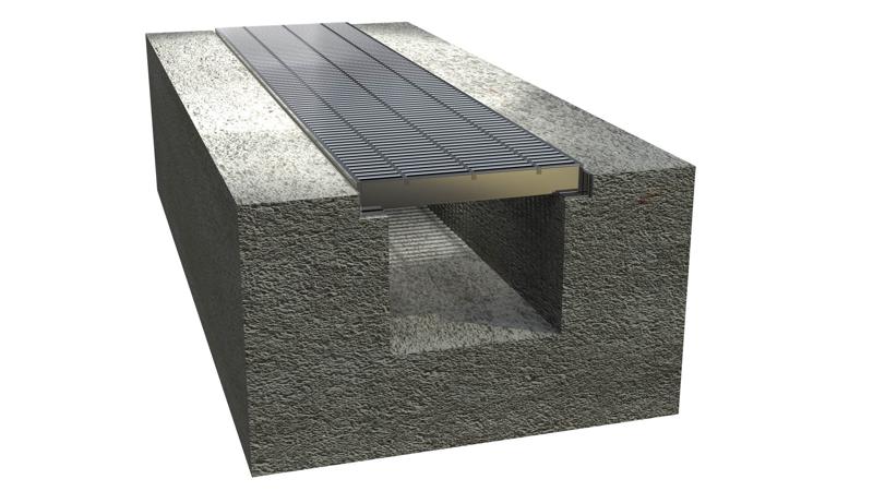
Grated trench drain
- Minimise use when possible due to high maintenance requirement.
- Where a trench drain crosses perpendicular to a path of travel, select grates which are designed to prevent ‘tramlining’ of bicycle wheels, wheelchairs and prams.
- Select slip resistant trench grates such as Slip NOT (or equivalent).
- Avoid using metal grates where bare feet may come into contact with heated grate/lid materials, or apply a heat resistant, pedestrian grade anti-slip coating.
- For pedestrian paths select small gap grates designed to resist the possibility of high heeled shoes being caught between the bars.
- Grates are selected by trench pit size (the internal measurement of the trench drain).
- Force applied to drainage grates is measured in kilonewtons (kN is 1 kilogram of mass at the rate of 1 metre per second squared). This is the international standardised unit of forces and is part of the international system of units (SI).
- Select grates with a suitable load classification for the required application.
- Install a grated trench drain adjacent to amenities buildings to capture and direct waste water from cleaning services away from pathways and garden beds as cleaning products may harm plants.
See Table 2: Drainage grates load rating requirements for further guidance.
Table 2: Drainage grates load rating requirements
Grate class and load | Recommended use | End user |
A (10 kN) | Paths for pedestrians and pedal cyclists | 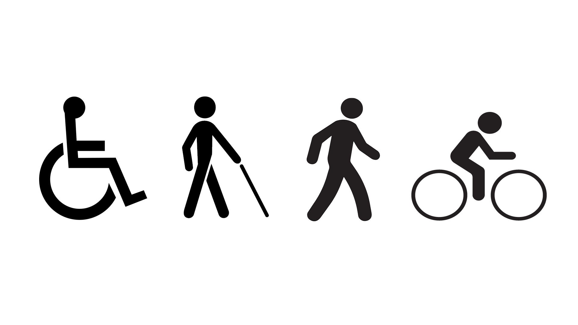 |
B (80 kN) | Paths for pedestrians, light tractor vehicles and livestock |  |
C (150 kN) | Malls and pedestrian areas open to slow moving commercial vehicles | 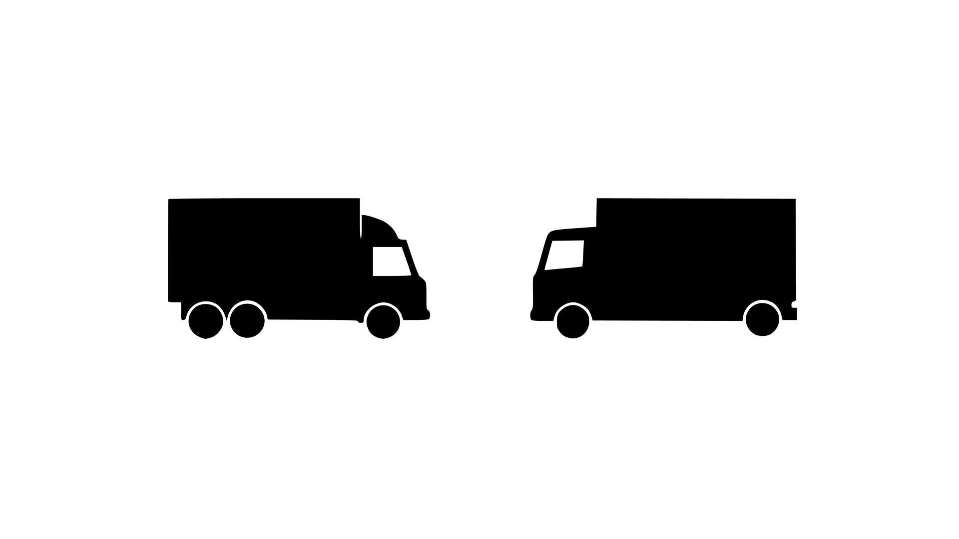 |
D (210 kN) | Roads and areas open to commercial vehicles. | 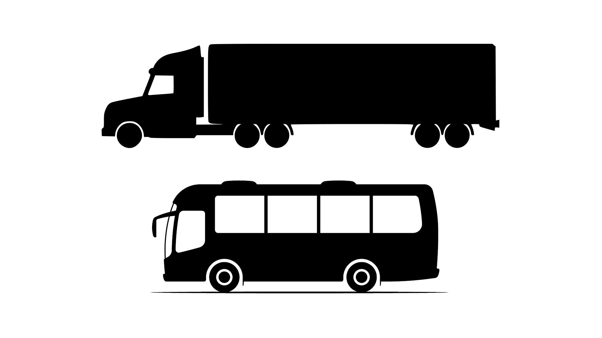 |
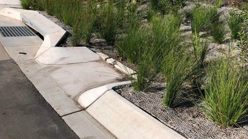
Open flow channel (swales)
- For open flow channels and swales, the design should be in accordance with QUDM.
- Used to minimise piped stormwater drainage systems.
- Velocities should be kept low within swales to avoid scouring. They are designed to ensure that the depth-velocity limit of 400 mm2/s is not exceeded for all flows up to the major flow event.
- Where drainage swales are turfed (preferred option), a maximum of 1:4 slope (1:6 or shallower is preferred) for mowing with a 2.0 m wide deck mower.
- Vegetated swales can be turf (preferred), sedges and tufted grasses.
- Rock lined swales are NOT preferred and must be approved by asset custodian. If installed, consider the following:
- Any loose rock lined drain should include a low planted buffer area both sides of the drain. Buffer planting separates loose rocks and turfed areas to prevent rocks becoming missiles when grass cutting or lawn mowing equipment is being used.
- Where there is a high potential for vandalism (such as removal of rocks from a rock lined drain), the rocks must be embedded in concrete or sealed in place using a suitable adhesive product.
- Any loose dry creek bed rocks within 50 m of play ground equipment or safety surfacing, must have the rocks secured into concrete, as loose rocks:
- can be used as projectiles
- contaminate safety surfacing
- can be used to damage equipment
- have to be hand removed from turfed areas as they become a projectile when mowed.
See LIM Play spaces for further guidance.
- Allow maintenance access across or around a swale drain to allow for machinery and vehicles.
- Sub surface materials must be suitable for buried applications.
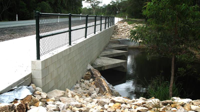
Box and piped culverts with overpass
- For culverts and a piped overpass, the design should be in accordance with QUDM.
- Box culverts may be used where low vertical clearances exist and must be as follows:
- constructed from precast reinforced concrete, plastic or other approved material
- a minimum height dimension of 375 mm
- large enough to carry flood water
- the culvert floor must be at the level of natural drainage.
- They are most effective in natural drains where minimum excavation is required.
- Are designed for the appropriate average recurrence interval (ARI) in accordance with the Queensland Urban Drainage Manual (QUDM).
- May be designed for vehicle crossover, pedestrian bridge or fauna passage.
- Kerb rail, barrier fence and balustrade may be required. See AS 2156.2 – Walking tracks infrastructure design for further guidance.
- Consider a screened inlet to minimise risk of unwanted access.
See LIM Environmental management of fauna and flora for further guidance.
Stormwater quality management considerations
Infrastructure designed to improve or protect downstream systems from pollutants by reducing the amount of pollutants entering creeks, rivers and bays.
This infrastructure may:
- be required when it is impossible to prevent pollutants from entering the stormwater network
- incur significant construction costs and on-going maintenance costs
- require ongoing inspection, monitoring, clean-out and waste disposal procedures
- require specialist input to ensure an appropriate stormwater management treatment train is designed.
See the following guidelines for further guidance:
- Brisbane City Council's Urban Management Division Part C Water Quality Management Guidelines.
- LIM Water sensitive urban design (WSUD).
Water management for paths/trails – Council requirements
Effective drainage construction ensures a lasting, maintenance free facility. The following are a series of water management design options to redirect surface and sub-surface water.
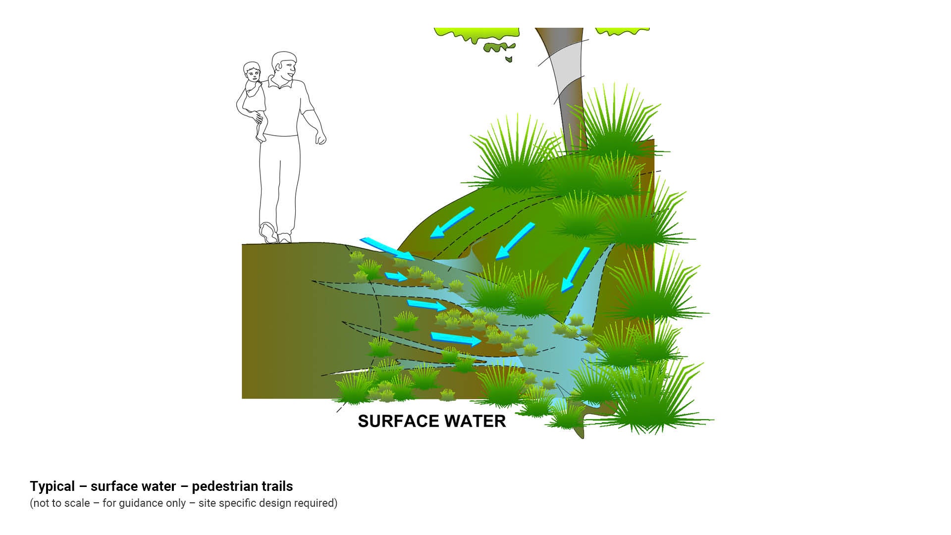
Surface water (paths/trails)
- Surface water runoff is the result of rainfall, ground water springs, rivers, lakes, wetlands and seepage.
- Trails may intercept surface water and direct it along the trail surface. Structures to control surface water are required at appropriate intervals along the trail, depending on rainfall pattern, trail surface material and local grade.
- The aim is to catch and redirect water away from the trail surface and to keep water velocity low to protect the trail surface from erosion.
- The trail can be shaped (crowned at the centre) to direct surface water off the trail.
- Cross fall can be used on any hardened, stable trail and is ideal for erosion resistant soils. Grades should be minor to moderate.
- Open side drains may be used to catch water to drain the trail.
- These options can be used alone or in combination with sub-surface drainage solutions to address water management.
See Figure 2: Typical – surface water – pedestrian trails.
Figure 2: Typical – surface water – pedestrian trails
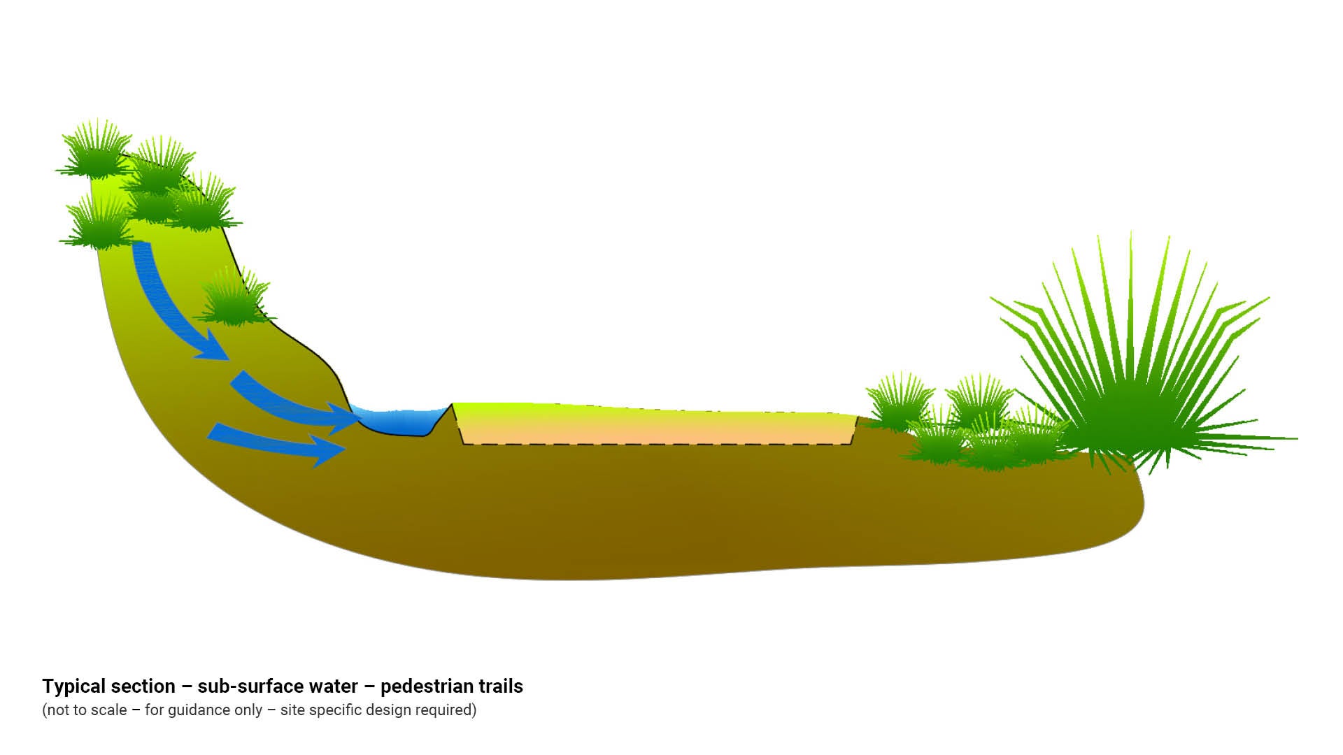
Sub-surface water (paths/trails)
- Sub-surface water (groundwater) is located beneath the earth’s surface.
- Drainage solutions for sub-surface water include open side drains, culverts, piped drains and turnpikes.
- These options may be used alone or in combination with surface drainage solutions to address water management.
- At locations which become inundated, a boardwalk may be required (when it is impractical to relocate a trail).
See Figure 3: Typical section – sub-surface water – pedestrian trails.
Figure 3: Typical section – sub-surface water – pedestrian trails
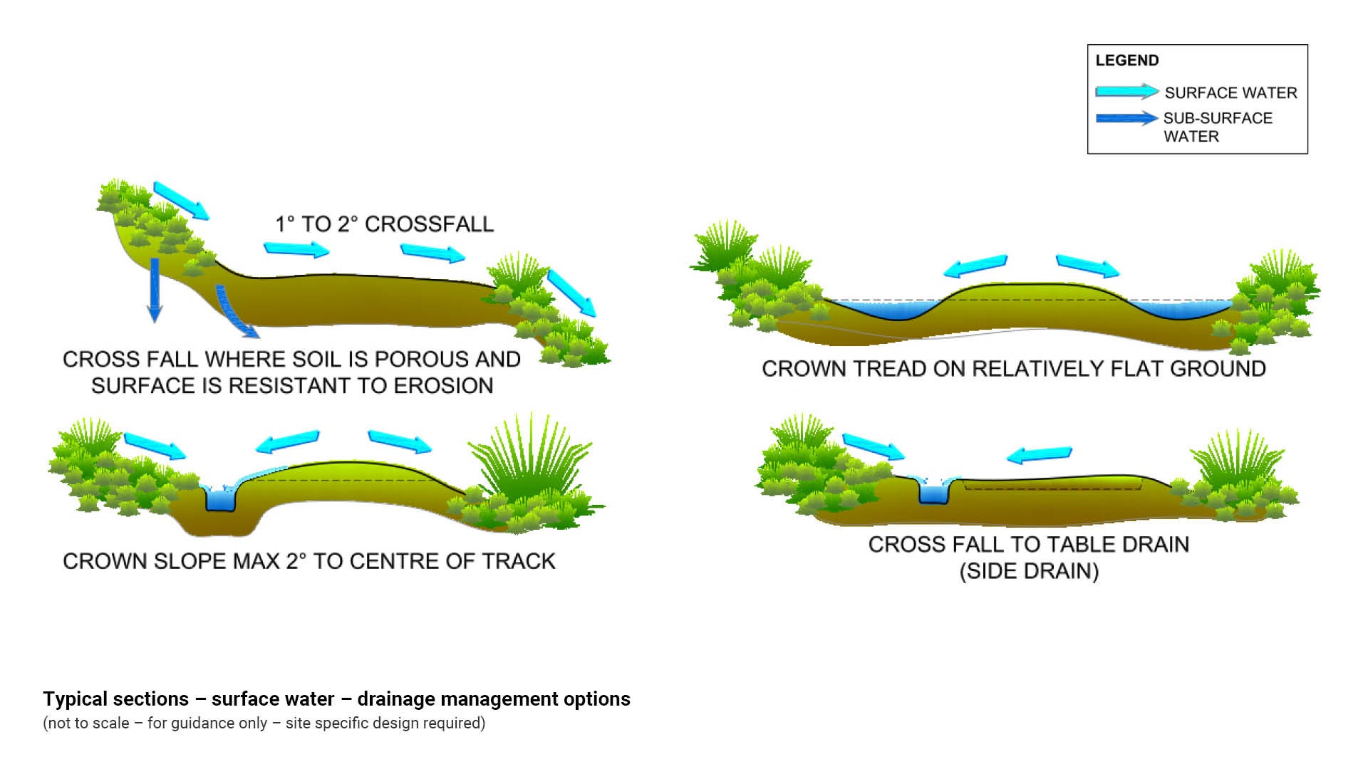
Surface water – drainage management options
The following diagrams illustrate a range of drainage options which may be implemented to redirect surface water runoff for paths/trails construction.
See Figure 4: Typical sections – surface water – drainage management options.
Figure 4: Typical sections – surface water – drainage management options
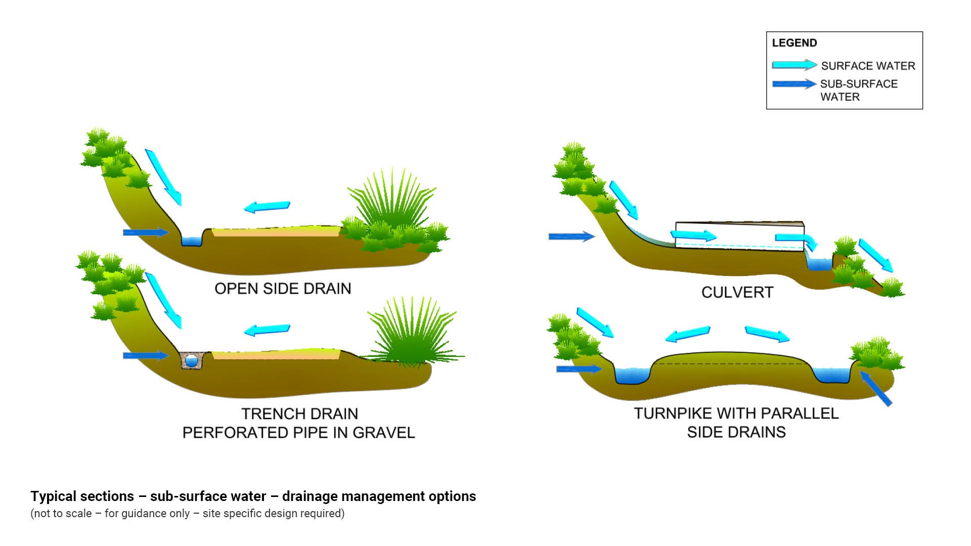
Sub-surface water – drainage management options
The following diagrams illustrate a range of drainage options which may be used to redirect sub-surface water or a combination of surface and sub-surface water runoff for paths/trails construction.
See Figure 5: Typical sections – sub-surface water – drainage management options.
Figure 5: Typical sections – sub-surface water – drainage management options
Drainage management solutions (paths/trails)
Cross fall (paths/trails) (drainage solution)
- Cross fall and crowns allow water to flow directly across the path/trail.
- Use this water management solution where surface grade is not excessive (such as 1:10) and soils are resistant to erosion.
- A crowned trail should be sloped towards the centre at a maximum 2%.
- Install trail cross fall at between 2.5% and 5%.
See Figure 3: Surface water – drainage management options.
Table (side) drains (drainage solution)
- Table drains are used to intercept both surface and sub-surface water and carry it to dispersal areas.
- This type of drain is suitable for side slope trails with a sub-surface water problem or where cross fall drainage is inappropriate.
- Silt traps and frequent cross drains may be necessary to slow water velocity and to prevent scouring.
- Table drains should be as close as possible to the trail edge.
- Lining should be rocks, free draining granular material or corrugated, perforated PVC (polyvinyl chloride) pipe.
- Provide frequent crossing or discharge points to prevent build-up of large volumes of water.
- Path/trail surface should be crowned or cross fall installed to drain water to side drains.
See Figure 4: Surface water – drainage management options.
Turnpikes (drainage solution)
A path/trail formation with a raised centre tread excavated from parallel side drains:
- Turnpikes are practical for grades up to 10%.
- The paths/trails are built from appropriate fill material excavated from parallel side drains.
- They are useful in flat, low land or water logged areas.
- Cross drains, culverts and water dispersal drains should also be installed at regular intervals.
- Table drains (side drains) should be large enough to cope with heavy rainfall events.
- Turnpikes are easy and cheap to construct.
See Figure 5: Typical sections – sub-surface water – drainage management options.
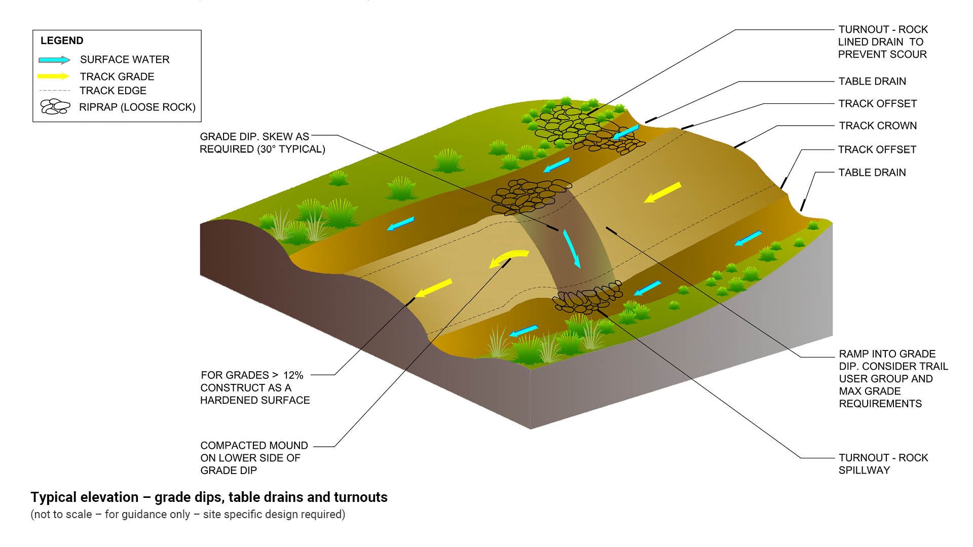
Grade dips and turnouts (drainage solution)
Grade dips are used to remove water at frequent intervals along a path/trail. Turnouts are short sections of extra width trail comprised of rock lined drain, installed to prevent scouring. Grade dips and turnouts should have the following characteristics:
- Designed into the path/trail at regular intervals, dictated by path/trail grade and natural soil type.
- Path/trail surface is out-sloped at the low point of the grade dip to divert water from the path/trail.
- Path/trail grades should be minor to moderate where grade dips and turnouts are used.
- Grade dips located on side slopes.
- Install rock lined turnouts to assist with dispersal of runoff.
See the following table and figures for further guidance:
- Table 3: Recommended spacing for grade dips and turnouts.
- Figure 5: Typical sections – sub-surface water – drainage management options.
- Figure 6: Typical elevation – grade dips, table drains and turnouts.
Table 3: Recommended spacing for grade dips and turnouts
Grade % | Spacing |
2% | 75 m |
5% | 40 m |
10% | 25 m |
18% | 20 m |
20% | 13 m |
30% | 10 m |
Figure 6: Typical elevation – grade dips, table drains and turnouts
Culverts (drainage solution)
A culvert is a hydraulic structure which may carry flood waters, drainage flows and natural streams.
- Culverts may be round, elliptical or box shaped.
- Materials may be concrete, galvanised steel, aluminium or high density polyethylene (HDPE).
- Are used to pass water under a path/trail in moderate to high water volume areas where bridges are not warranted.
- The minimum recommended culvert size in all areas is 300 mm.
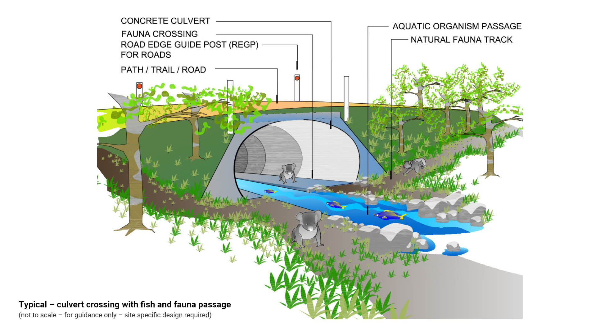
- Ensure the culvert is aquatic organism compatible (fish friendly) if necessary.
- Ensure fauna passage is considered in the culvert design.
- Where an underpass crosses a wide road, install surface grills (designed for traffic loading) midway to allow light and airflow for fauna.
- Consult Queensland Urban Drainage Manual (QUDM) by Queensland Government Natural Resources and Water.
- Culvert design is the result of hydraulic analysis of considerations such as topography, average rainfall intervals (ARI) and catchment area.
- Australian Rainfall and Runoff (ARR) is a design guide for flood estimation and hydraulic calculation.
- Culverts are designed to carry flood waters and prevent blockage.
- When designing culverts at sites used for stock crossing, consider the volume, frequency and type of stock which need to cross as well as any water which may pass through the culvert.
- Culverts are to be bedded and backfilled as per Transport and Main Roads (DTMR) Installation, Bedding and Filling/Backfilling Against/Over Culverts – standard drawing UMS 311 Bedding methods for rigid and flexible drainage pipes.
- Headwall and apron design is to be as per DTMR Construction of reinforced concrete wingwalls and aprons for pipe diameter up to 2400, drawings MR 1304, 1305, 1306.
- Consult a suitably qualified hydrologist for hydraulic analysis.
- A screened inlet may be required, to minimise risk of access.
- A barrier and fence may be required at culvert ends. Site specific analysis is necessary.
- For barrier and fence requirements see AS 2156.2 – Walking tracks Part 2: Infrastructure design.
- Urban waterways and stormwater drainage systems can represent a significant safety risk during storms and flood. Risk may be associated with a person deliberately entering a drain or waterway, or as a result of an accidental slip or fall. This risk can be managed successfully through the use of inlet screens to prevent entry of people into a pipe or culvert.
See the following for further guidance:
- Figure 7: Typical section – culvert crossing
- Figure 8: Typical – culvert crossing with fish and fauna passage.
- LIM Environmental management of fauna and flora.
Figure 7: Typical section – culvert crossing
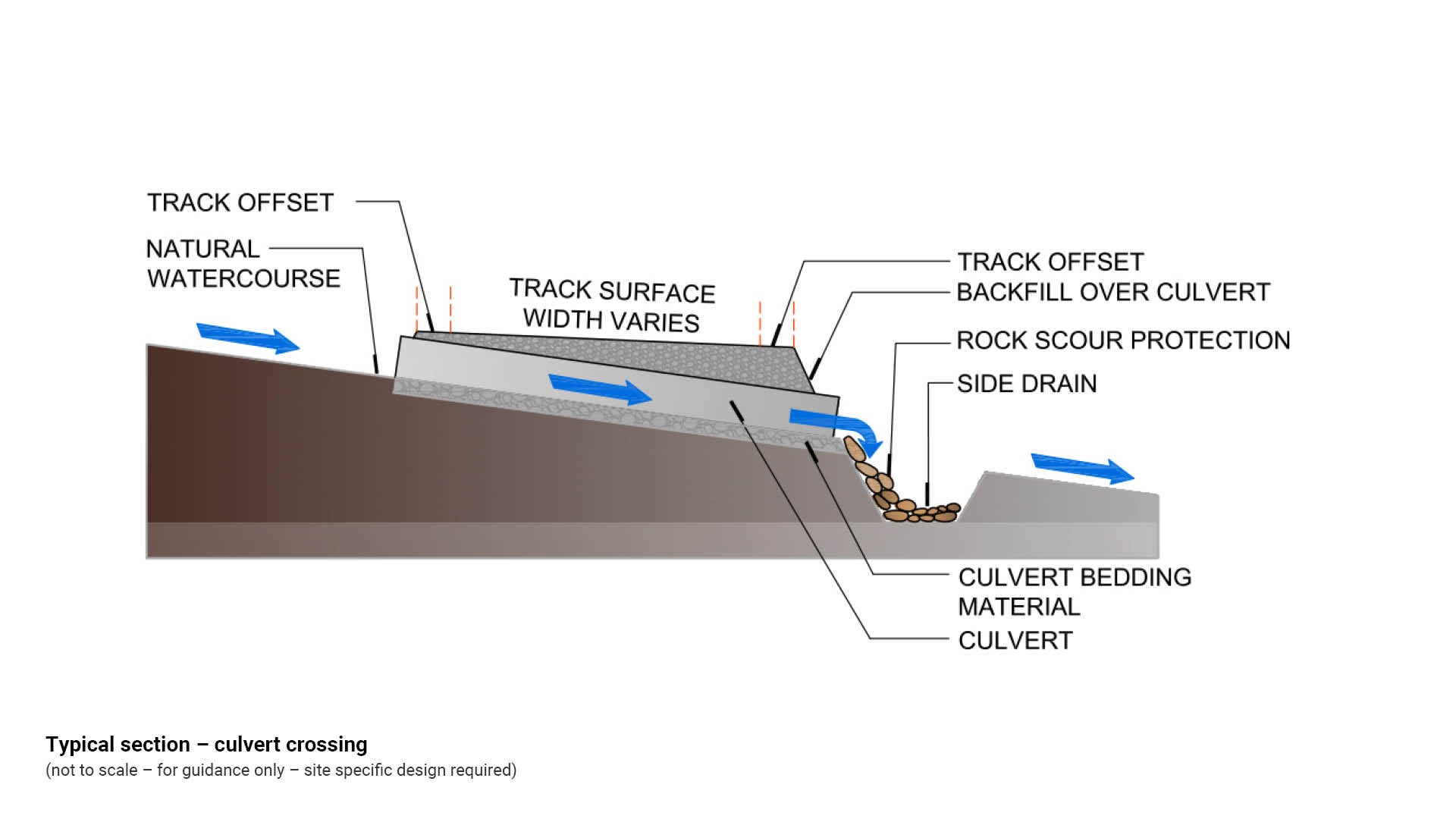
Figure 8: Typical – culvert crossing with fish and fauna passage
Waterway crossings (drainage solution)
Waterway crossings should be designed to minimise environmental harm to waterways.
- Use an existing crossing site where possible.
- If a new crossing is needed select the site based upon the following:
- a stream reach which is straight, well defined and unobstructed
- a location where a ‘right of way’ exists
- the geology and soil conditions should be stable with minimum erosion and meandering
- avoid wetlands and flood plains
- avoid areas which contain threatened species
- avoid areas of significant cultural heritage.
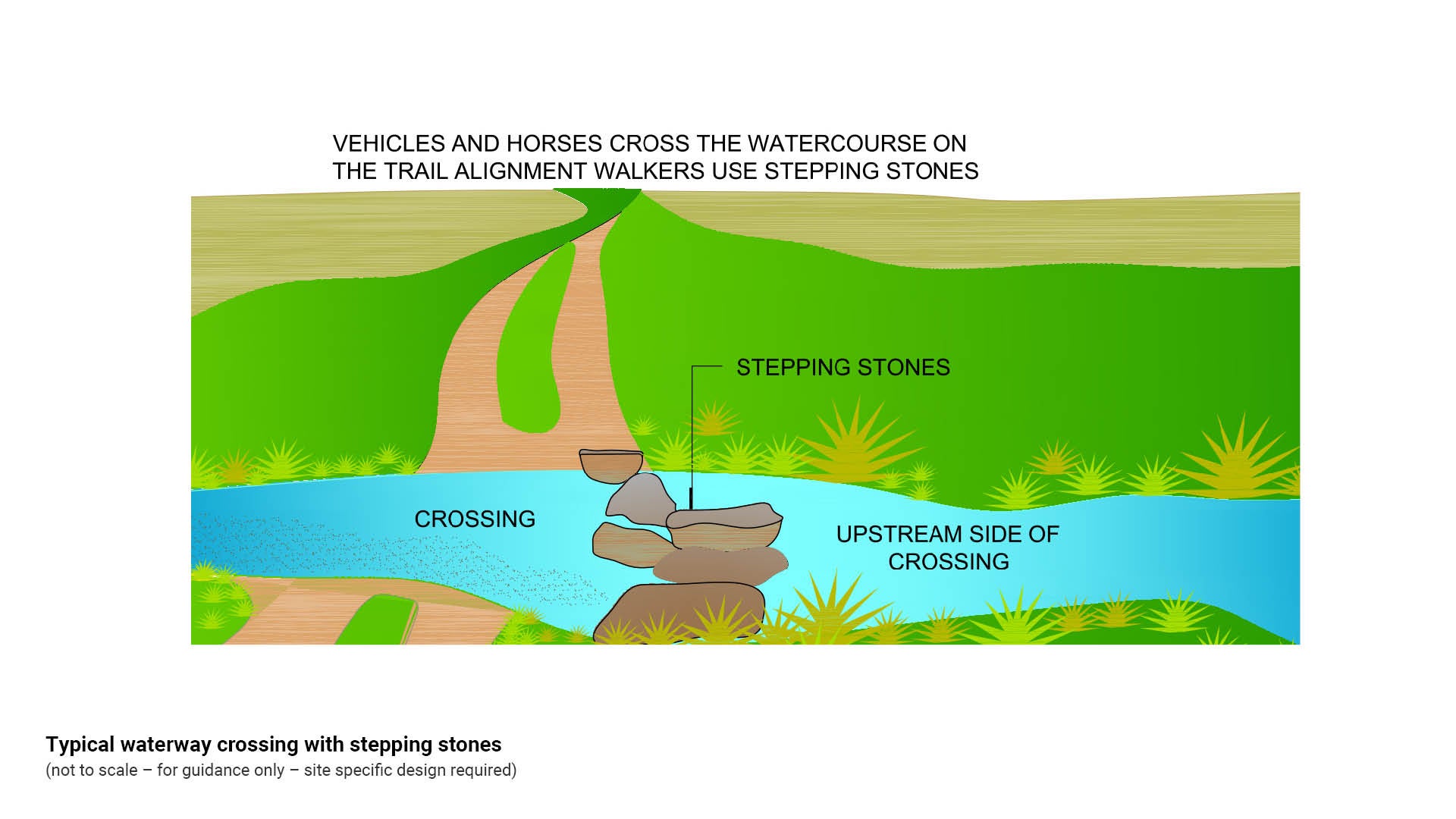
See Figure 9: Typical waterway crossing with stepping stones.
Stepping stones (drainage solution)
Locate stepping stones as follows:
- At a stream crossing with wider, shallower sections
- With the aim to provide solid footing at a consistent depth from one stream bank to another
- Place stepping stones on the upstream side of a crossing
- Ensure rocks are large enough to provide stable footing
- Do not block passage for fish or other aquatic organisms
- Do not block stream flow
- Queensland Department of Natural Resources and Mines (DNRM) Riverine Protection Permit may be required for permission to undertake such activities in a watercourse.
See the following for further guidance:
- Figure 9: Typical waterway crossing with stepping stones.
- Self-assessable codes by Department of Natural Resources and Mines (DNRM).
Figure 9: Typical waterway crossing with stepping stones
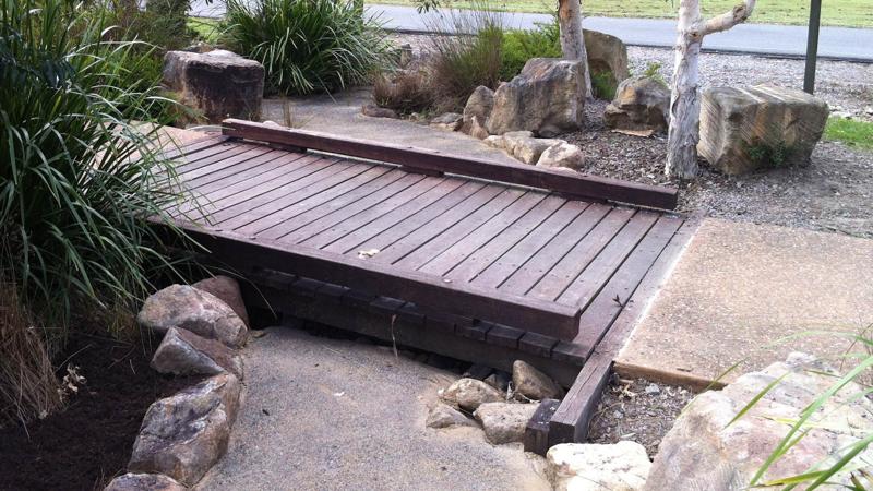
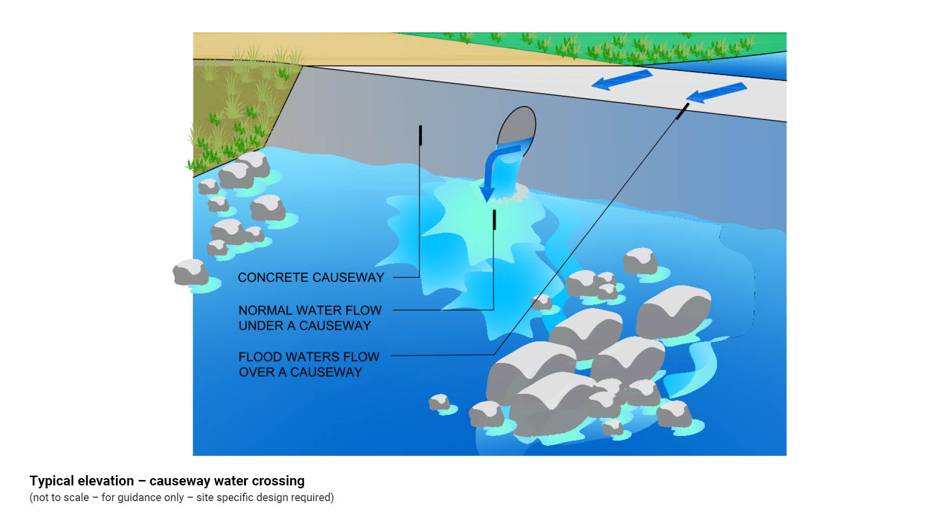
Causeways (drainage solution)
Causeways are constructed water crossings which:
- Are constructed on the base of the stream bed
- Perpendicular to the waterway to preserve the waterway hydraulic regime
- Must comprise erosion proof material (stone or concrete)
- Have both ends of the causeway ‘keyed’ into the banks
- Allow normal stream flow to pass under the causeway
- Allow flood waters to flow over the causeway
- Are suitable for watercourses where intensive use is not anticipated
- Are suitable for wide shallow streams where it is too expensive to construct a bridge
- State Government Department of Natural Resources and Mines (DNRM) Riverine Protection Permit may be required for permission to undertake such activities in a watercourse
- May fall within self-assessable codes for waterway barrier works by Department of Natural Resources and Mines (DNRM).
See Figure 10: Typical elevation – causeway water crossing.
Figure 10: Typical elevation – causeway water crossing
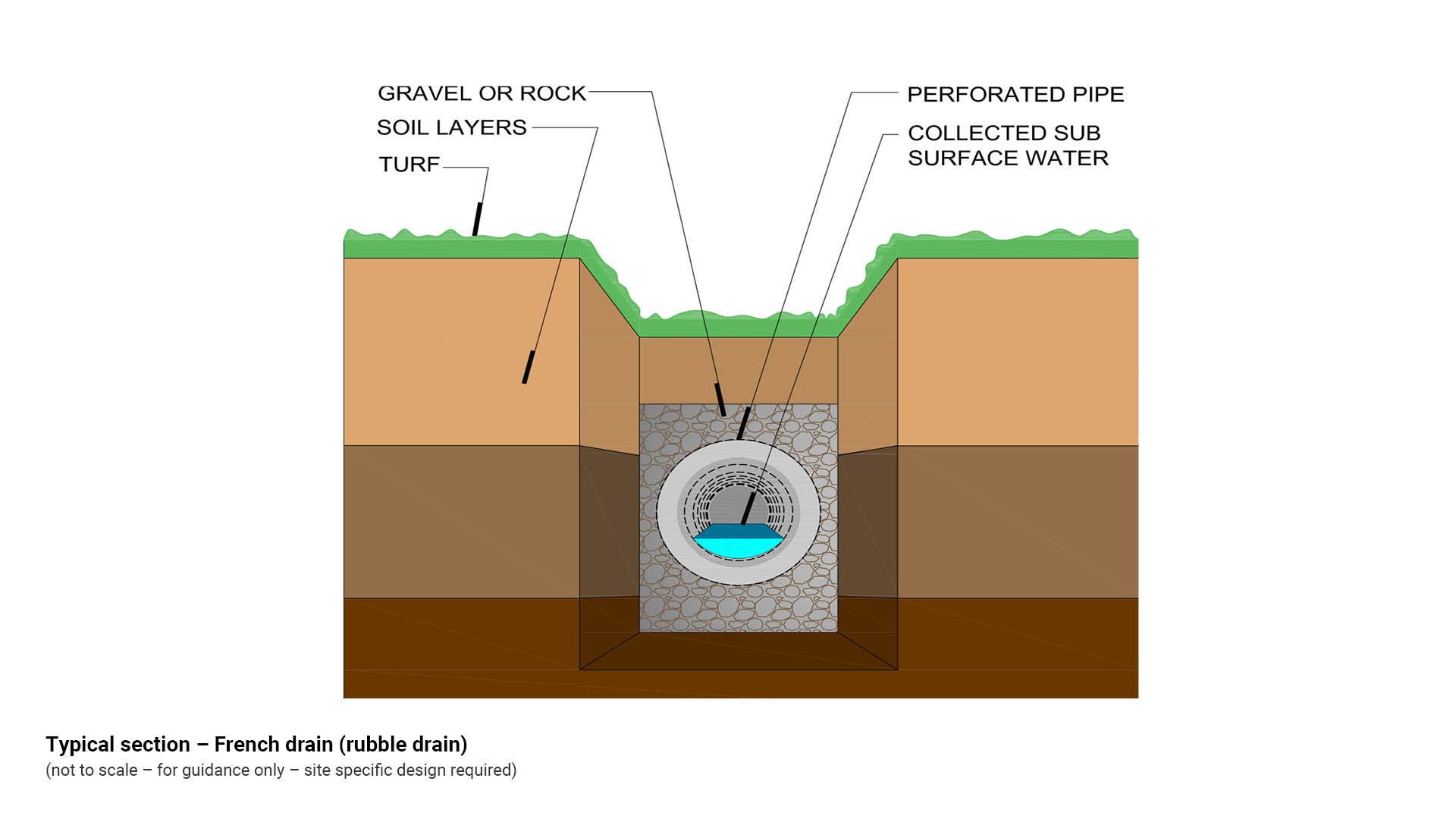
French drain (also known as rubble drain) (drainage solution)
A French drain is a rubble drain or rock lined drain which redirects surface and sub-surface water away from an area and is comprised of:
- A rock lined trench covered with gravel or rock, and may contain a perforated pipe
- Geo-fabric may be used to prevent the migration of drainage material and to prevent roots from entering and clogging the drainage pipe
- Perforations in drainage pipe (agricultural pipe) are used to drain the area along the length of the pipe and discharge any surplus water at its end
- Multiple pipes may be used where a French drain needs to be widened, dependent upon expected volumes of rainwater or runoff
- A design suitable for low flows only
- A design which is suitable for use on steep slopes.
See the following for further guidance:
- Figure 11: Typical section – French drain (rubble drain)
- QUDM for a typical section of a soakage pit or low flow pipe system.
Figure 11: Typical section – French drain (rubble drain)
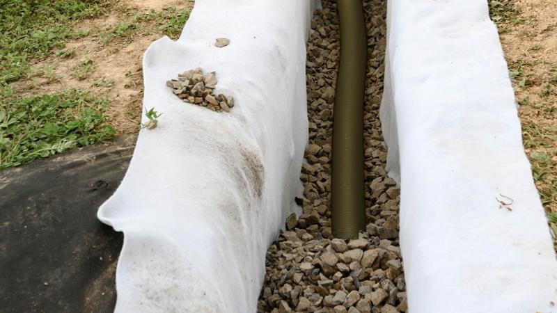
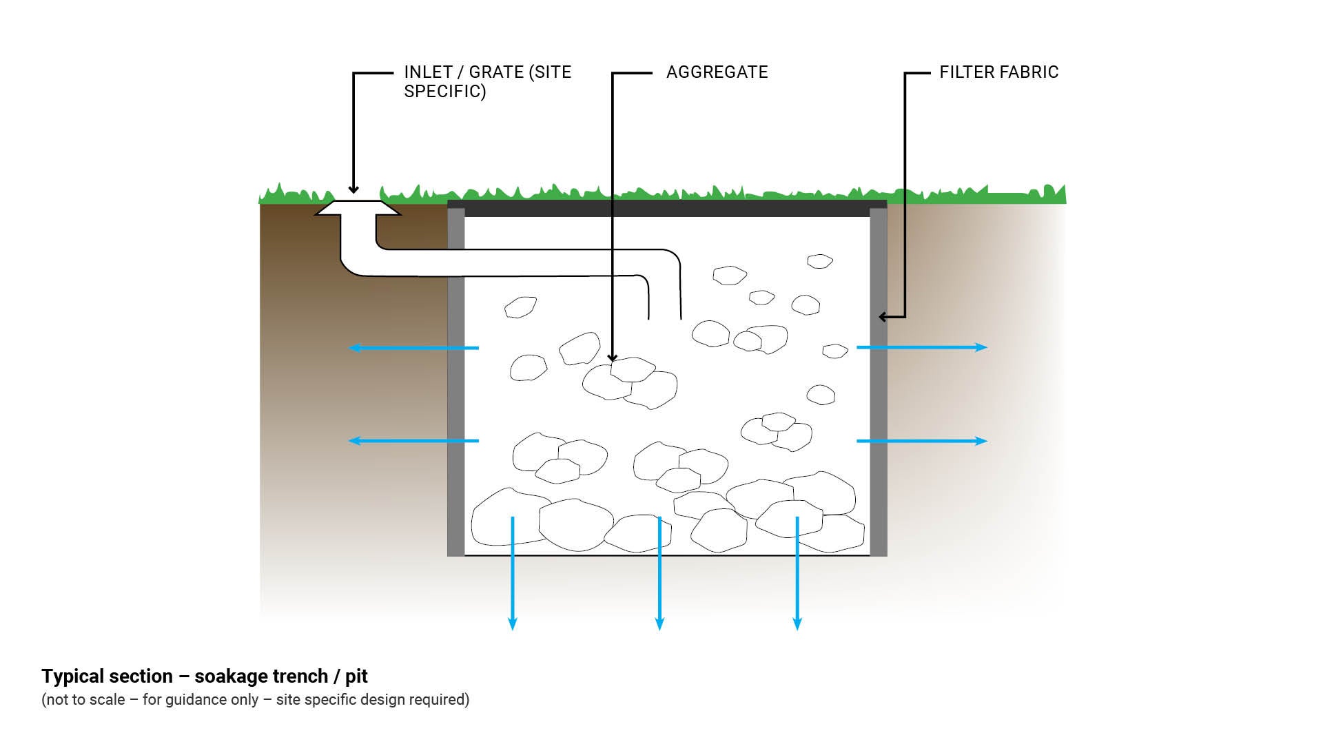
Soakage trench/pit
Soakage trenches or pits are required to remove water run-off where there is no reticulated stormwater.
A soakage trench or pit contains aggregate wrapped in filter fabric which redirects surface water underground and should be designed to be:
- Clear of existing and future tree roots
- Clear from underground services
- Accessed and maintained by machine
- Installed at locations where surface run off is insufficient and justifies ongoing maintenance.
- Site evaluation and soil testing is required for correct placement of soakage trench or pit.
See the following for further guidance:
- Figure 12: Typical section – soakage trench/pit
- LIM Taps for more information in regards to soakage trenches/pits.
Figure 12: Typical section – soakage trench/pit
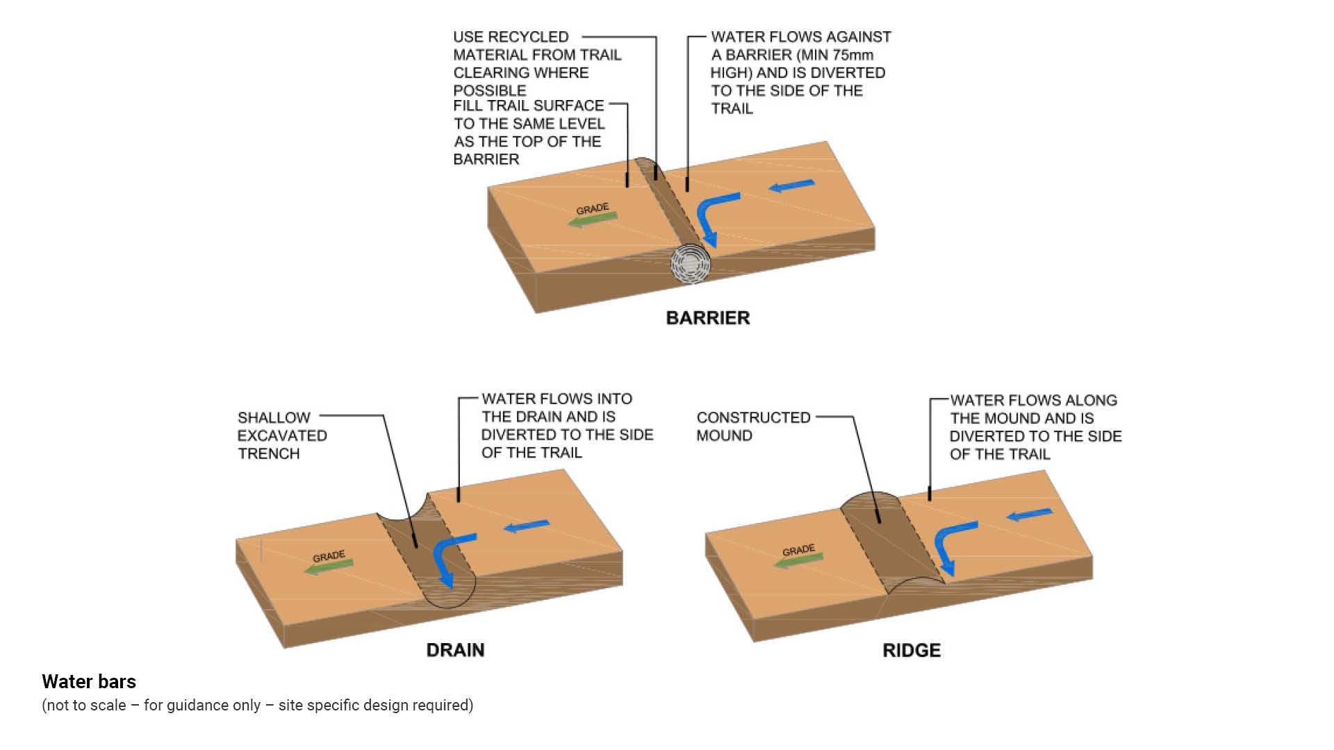
Water bars (drainage solution)
Water bars are diagonal channel deflectors installed across a path/trail surface.
- Water bars are used to divert surface water which would otherwise flow down the trail reaching destructive energy levels.
- As running water has enormous energy, the amount of sediment a flow can carry increases as the fifth power of velocity (the surface speed at which the water moves).
- Sediment laden water has the characteristics of liquid sandpaper however a well-placed water bar will deflect the kinetic energy that gravity gives to water.
- Volumes of water flowing down a path/trail can be reduced by constructing a series of water bars at regular intervals and at an angle of at least 10 degrees from perpendicular.
- There are three main types of water bar:
- a drain (shallow trench)
- a ridge (mound)
- a barrier.
- Sediment accumulates on the uphill side of a water bar and requires cleaning to preserve effectiveness
- Water bars may be constructed of:
- stabilised soil bermed (mounded) to resemble a speed hump
- timber
- stone
- compacted road base.
- Do not construct water bars where they may divert flow onto unstable slopes, unprotected erodible materials or fills or onto environmentally sensitive areas.
- Consider water bar spacing determined by trail grade and site specific conditions.
- Water bars may make access along the path/trail difficult for people with limited mobility.
See the following table and figure for further guidance:
- Table 4: Water bar material options
- Figure 13: Water bars.
Table 4: Water bar material options
Material | Consideration |
Timber |
|
Stone |
|
Compacted road base |
|
Stabilised soil |
|
Figure 13: Water bars
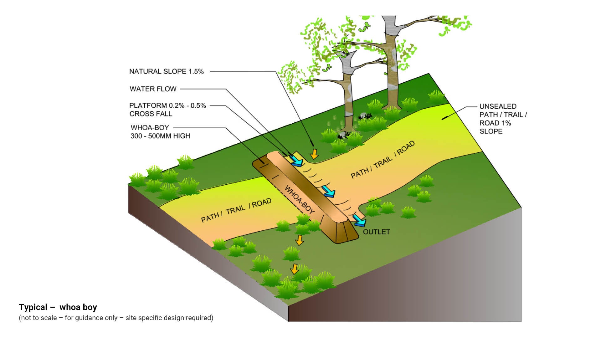
Whoa boys (drainage solution)
Whoa boy is the common name for a small trafficable water diversion bank constructed by earth moving machinery or by hand. Whoa boys may be found on outback roads, four wheel drive path/trails and walking trails.
The function of a whoa boy is to divert water flowing down a road or path/trail, back onto undisturbed land. Whoa boys may also be designed as a speed deterrent to slow traffic in environmentally sensitive areas.
Whoa boy design and construction is as follows:
- Shape an earth bank with a platform on the upslope side of a path/trail/road
- Design a whoa boy to ensure that no rain water will flow down the path/trail/road
- Design a whoa boy to ensure natural cross flow of water is maintained and is not diverted down the path/ trail/road
- Construct a platform which ensures that any water flowing across the slope does not cause soil erosion
- Gentle slopes require banks to be approximately 300 mm higher than the surrounding natural surface level
- Slopes steeper than 2.5% require banks approximately 500 mm higher than the surrounding natural surface level
- Wet down the whoa boy and compact the bank by rolling.
Whoa boy spacing
Spacing of whoa boys is determined by slope, natural watercourses and stable vegetated areas.
- Maximum required spacing of whoa boys on an open road is 120 m, when the slope is 1% and cross slope is 1.5%.
- Where there is a natural watercourse such as a creek crossing the road, place the whoa boy on the down slope side. This will ensure natural water flow is maintained.
Whoa boy outlet
- Where water is diverted from a road/trail using a whoa boy, the outlet area must be stable and vegetated to prevent erosion.
- Whoa boy spacing will therefore be determined by the occurrence of a suitably vegetated area.
See Figure 14: Typical – whoa boy.
Figure 14: Typical – whoa boy
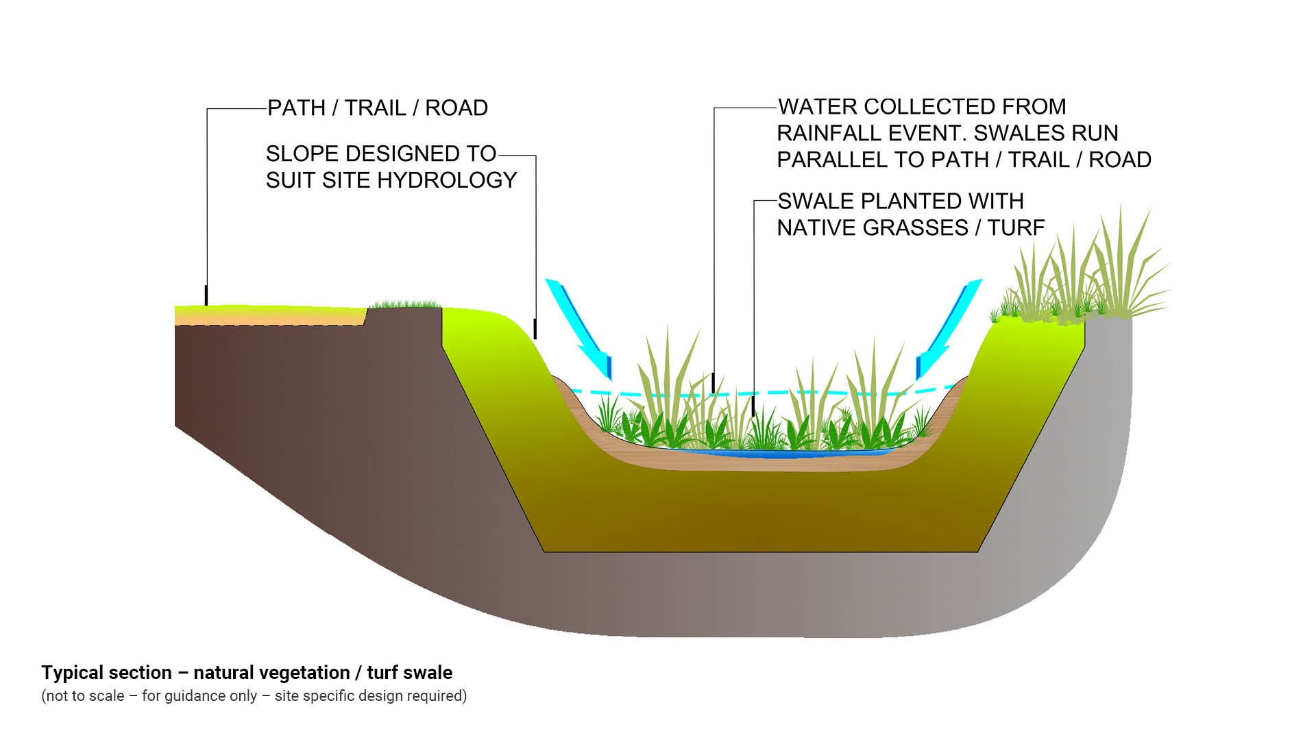
Swale drain (drainage solution)
A swale drain is a shallow channel designed to convey stormwater and is usually lined with turf or natural vegetation. The objective of a swale drain is to minimise the use of piped stormwater drainage systems and ensure overland flow paths are retained in the catchment helping to minimise risks during peak rainfall events. Key swale considerations include:
- Swales slow down stormwater flows
- Swales are suitable for side grades between 1% and 4%
- Longitudinal grades should typically be between 1% and 4%
- Swales which are too flat can become waterlogged or become stagnant ponds
- Typically designed for small scale contributing catchment areas of 1 to 2 ha
- Any loose rock lined drain should include a low planted buffer area both sides of the drain. Buffer planting separates loose rocks and turfed areas to prevent rocks becoming missiles when grass cutting or lawn mowing equipment is being used
- For details of the stormwater quality management considerations of swales see LIM Water sensitive urban design (WSUD).
See Figure 15: Typical section – natural vegetation/turf swale.
Figure 15: Typical section – natural vegetation/turf swale
Rock lined drains – safety measures
Rock lined drains should include a low planted buffer area both sides of the drain. Buffer planting separates loose rocks and turfed areas to prevent rocks becoming missiles when grass cutting or lawn mowing equipment is being used.
The following safety measures should be undertaken when designing a rock lined drain:
- Rock size is primarily dependent on the local flow velocity, rock shape, density and grading, and bank slope
- Crushed (angular) rock is generally more stable than rounded rock
- Water worn rounded rock from the local area is preferred for aesthetic reasons however a 36% increase in rock size is recommended for rounded rock
- Rock should be proportioned so that neither the breadth nor the thickness of a single rock is less than one third its length
- Typical thickness of rock layer should be sufficient to allow at least two overlapping layers of nominal rock size
- Rock should be durable and resistant to weathering
- Consult a suitably qualified engineer to determine the most appropriate rock size, type and installation treatment, to manage site drainage
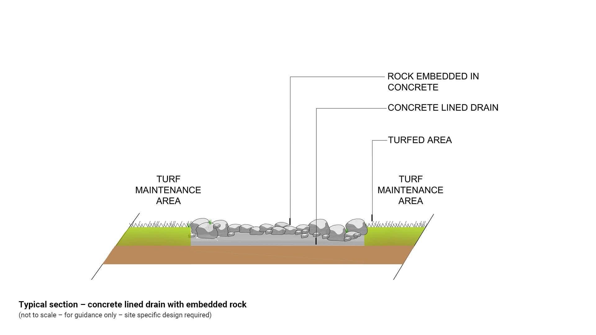
- Where there is a high potential for vandalism such as removal of rocks from a rock lined drain, the rocks should be embedded in concrete or sealed in place using a suitable adhesive product
- Suitable only for low sediment flow environments
- Used in constructed channels where ecological considerations are low
- Most successful on mild gradients and channels up to 1:20.
See the following figures for further guidance:
- Figure 16: Typical section – rock lined drain with planted safety buffer zone
- Figure 17: Typical section – concrete lined drain with embedded rock.
Figure 16: Typical section – rock lined drain with planted safety buffer zone
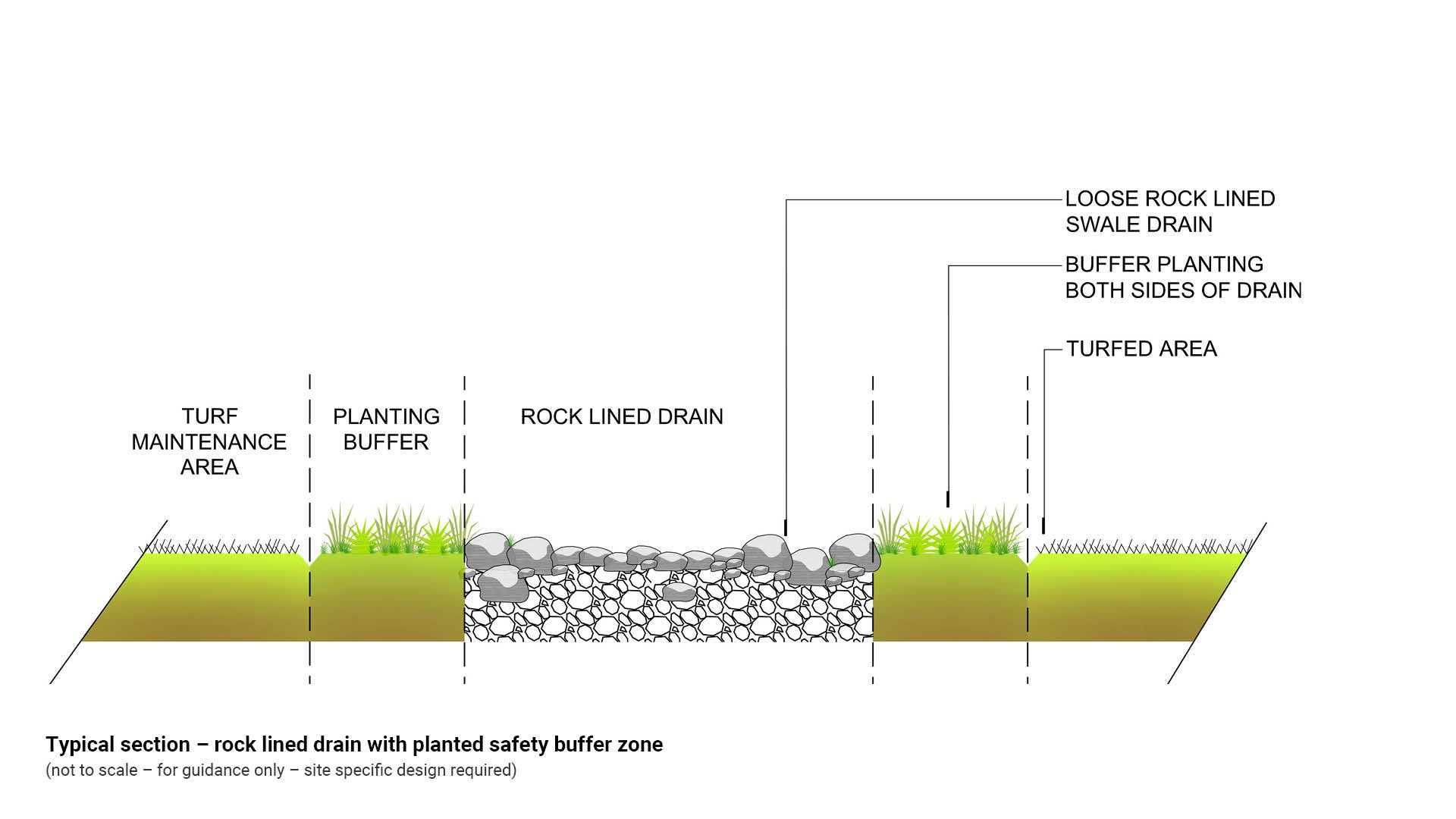
Figure 17: Typical section – concrete lined drain with embedded rock
This component is currently in development