Tree sensitive design (existing and new trees)
Existing trees
Existing trees can be compromised when construction or construction-related activities occur too close to them. While tree roots extent well beyond the canopy edge of a tree, a good rule of thumb is to at least protect all areas within a tree’s drip line.
Newly constructed or rehabilitated pathways present one of the greatest threats to existing trees and frequently lead to tree loss or damage.
Traditional footpath construction methods can damage trees through direct root loss, replacement of natural soils with compacted ground treatments (restricting the passage of oxygen) and replacement of permeable ground with impervious hard surfaces (preventing infiltration of water and air flow).
There are however numerous alternative methods of pathway construction that reduce or prevent impacts to trees.
Tree sensitive footpath design treatments
Tree sensitive footpath design treatments for existing trees include:
- realignment or relocation of pathways
- elevated pathways
- above grade pathways (no dig designs)
- no pathway.
Table 1: Tree sensitive design principles (existing trees)
Example illustration/description | Objectives | Treatment types |
Realignment or relocation of pathways 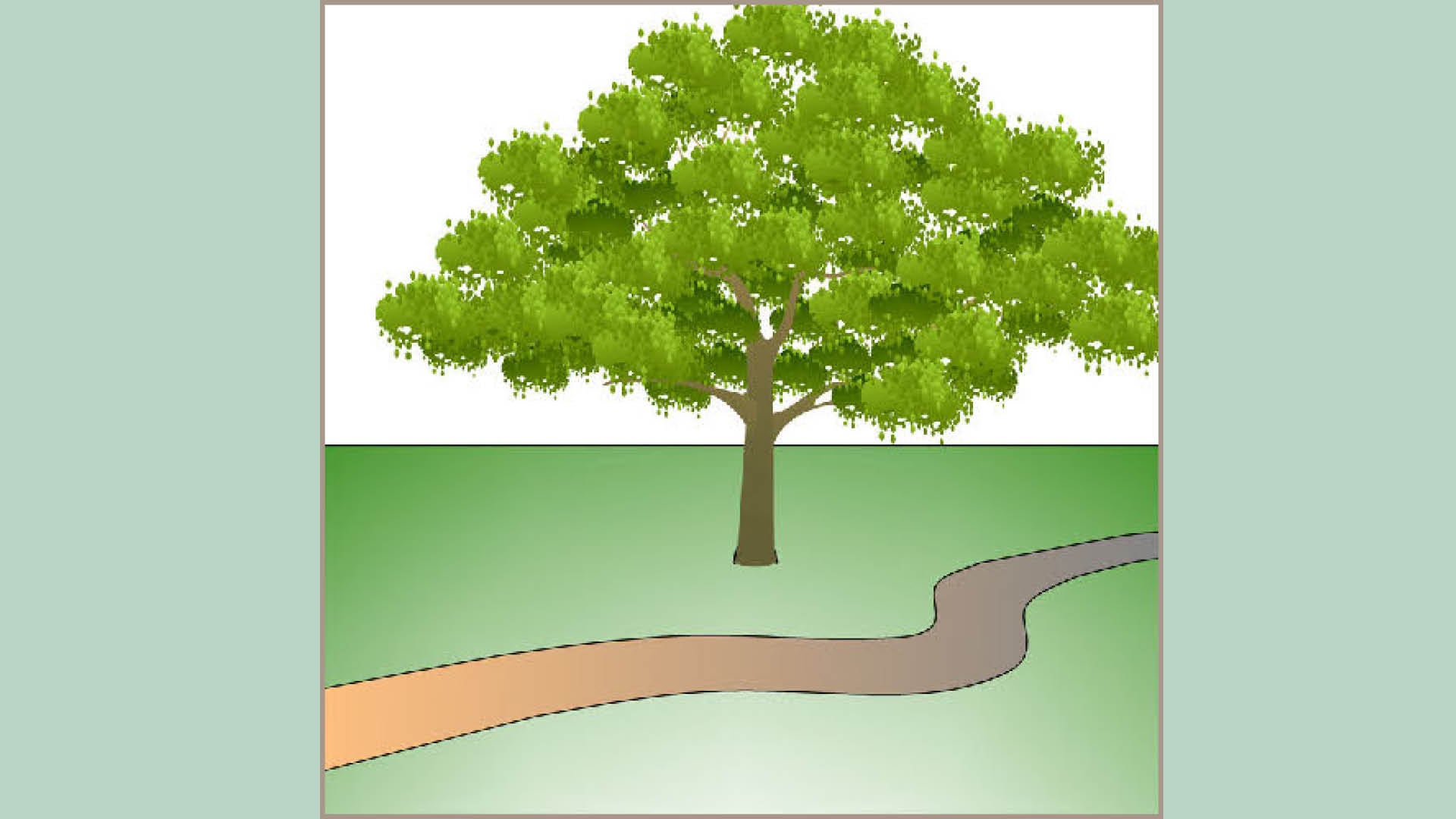 |
|
|
Elevated pathways 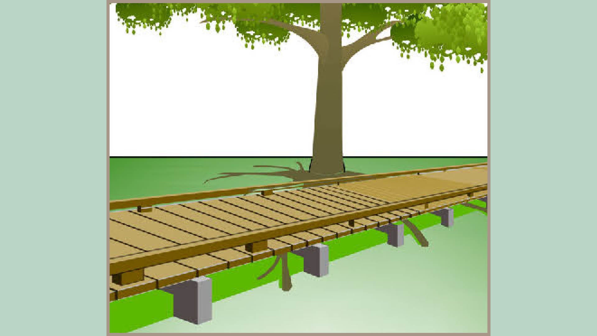 |
|
|
Above-grade pathways ('no dig') 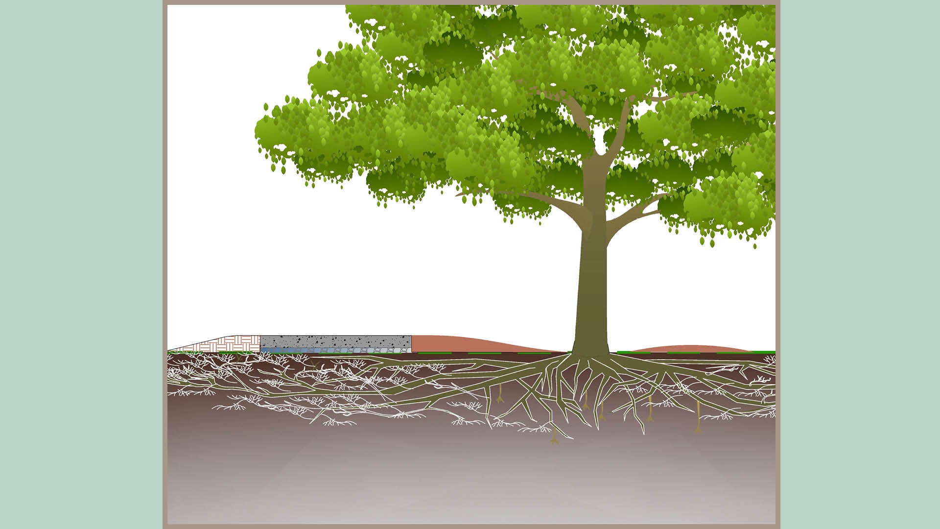 |
|
|
No pathway 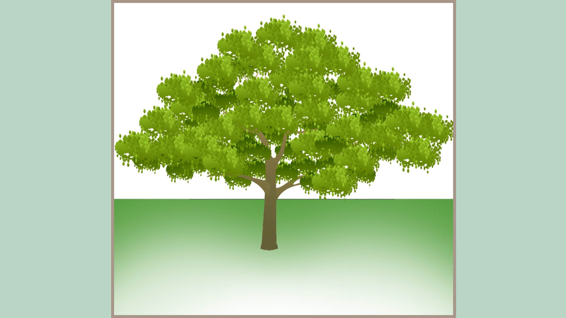 |
|
|
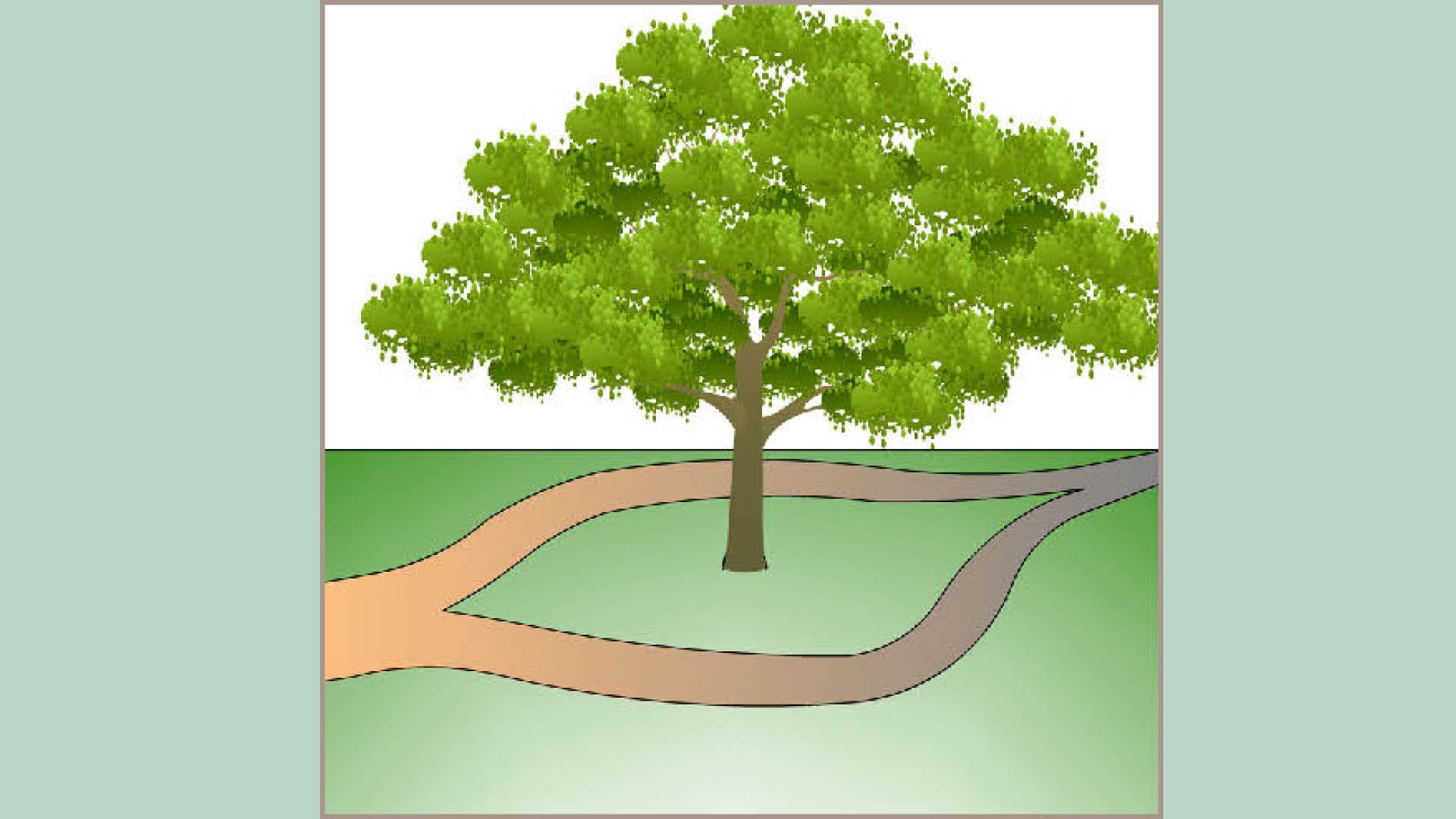
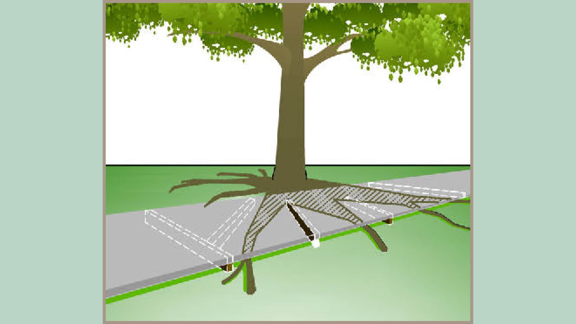
Realignment or relocation of pathways

Where a risk of damage has been identified, and the tree is considered valuable for retention, relocation or realignment of the pathway may be possible. This will avoid direct disturbance of the tree root zone or minimise the extent of disturbance that will be caused.
Pathway relocation aims to exclude the tree protection zone (TPZ) of a tree from new works altogether (see determining the extent of a TPZ in LIM Site setup (including tree protection) for further guidance).
Where several options for the location of a pathway are available, it is preferable to locate pathways in areas that offer limited potential for large tree establishment including sites that:
- are already disturbed
- do not conflict with a mature tree canopy
- have powerlines overhead or underground services directly beneath
- exhibit dense living and short distances between driveways
- contain very poor soils
- are heavily shaded by multi-story buildings
- have a multitude of street signs.

Options for relocation of pathways may include, but are not limited to:
- Construct pathway on opposite side of the road.
- Construct pathway behind existing trees, instead of in front of existing trees (where space permits and underground service conflicts do not prevent).
- Construct in front of kerb and channel (within road carriageway) where space permits and localised road narrowing is possible

Footpath alignments can be exploited so as to ensure that the number of trees of value exposed to the risk of damage is minimised. See Table 2: Treatment options for diversion or realignment of pathways for typical treatment options. Moreover, by enlisting sensitive design techniques, damage can be minimised further.
Table 2: Treatment options for diversion or realignment of pathways
Example illustration | Treatment description |
 |
Scalloped
Pathways that divert from a straight line directly adjacent to trees and immediately come back to alignment once past the tree (this method is also useful for creating new tree planting sites). |
 |
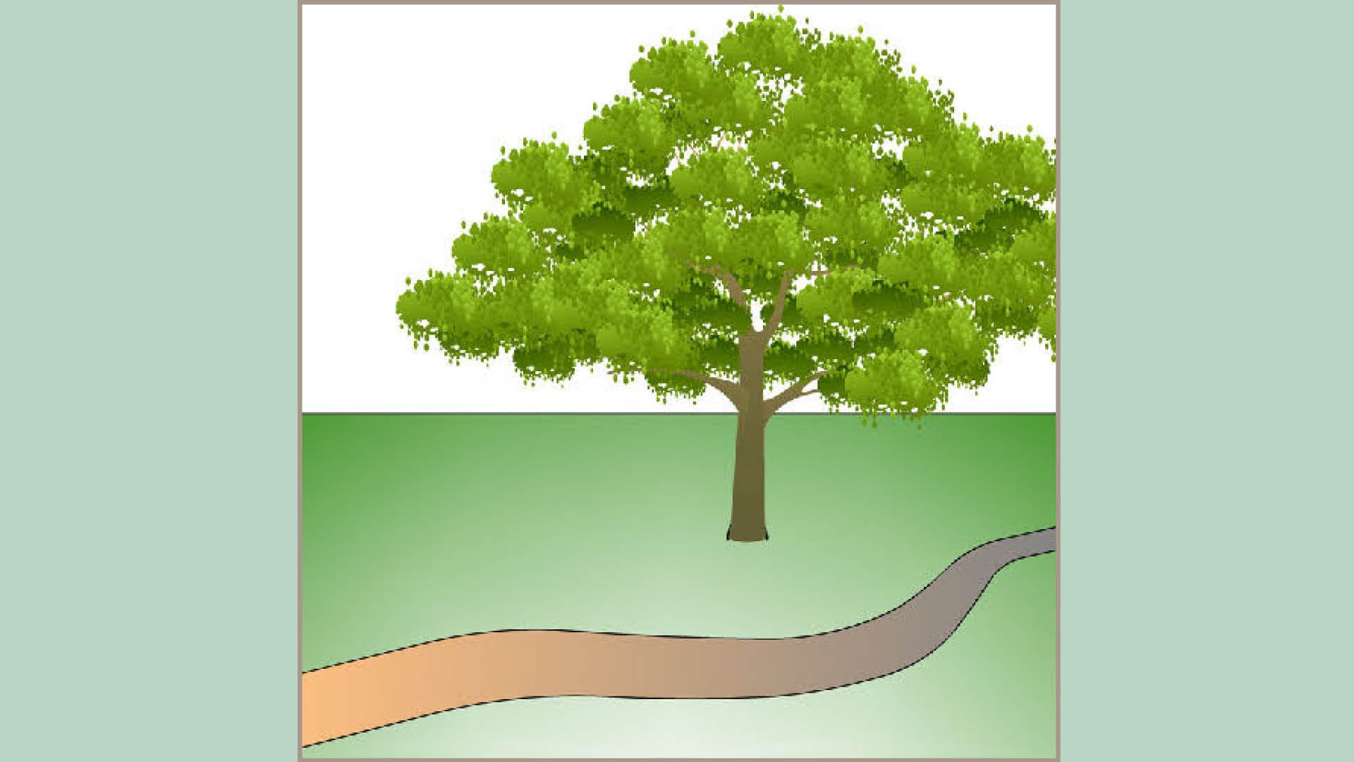
Pinched/isolated narrowing
Pathways where isolated narrowing occurs adjacent to trees (ensure sufficient pathway width is maintained). |
 |
Undulating
Pathways that follow the natural contour of the land instead of excavating to achieve a flat surface. |
|
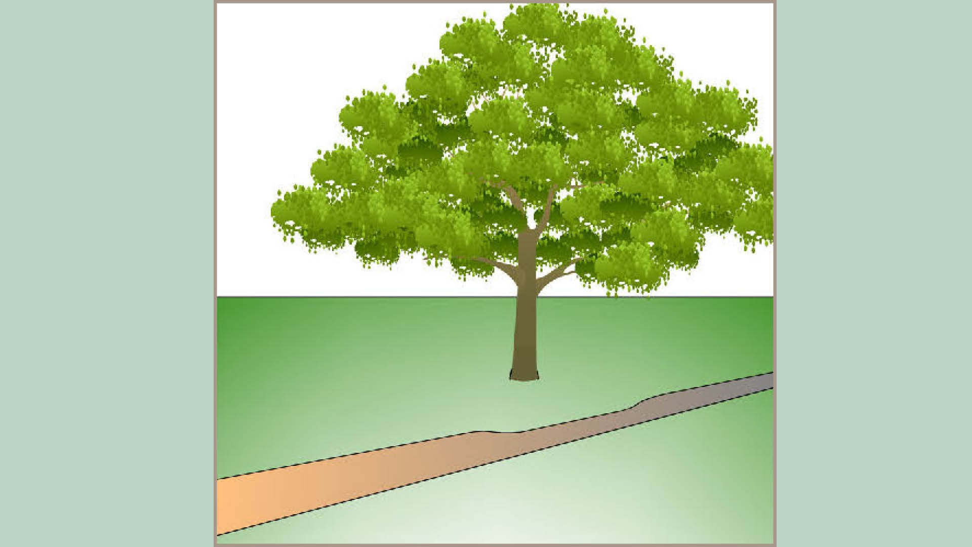
Meandering
Pathways that gently divert away from trees and come back to a straight line. |
 |
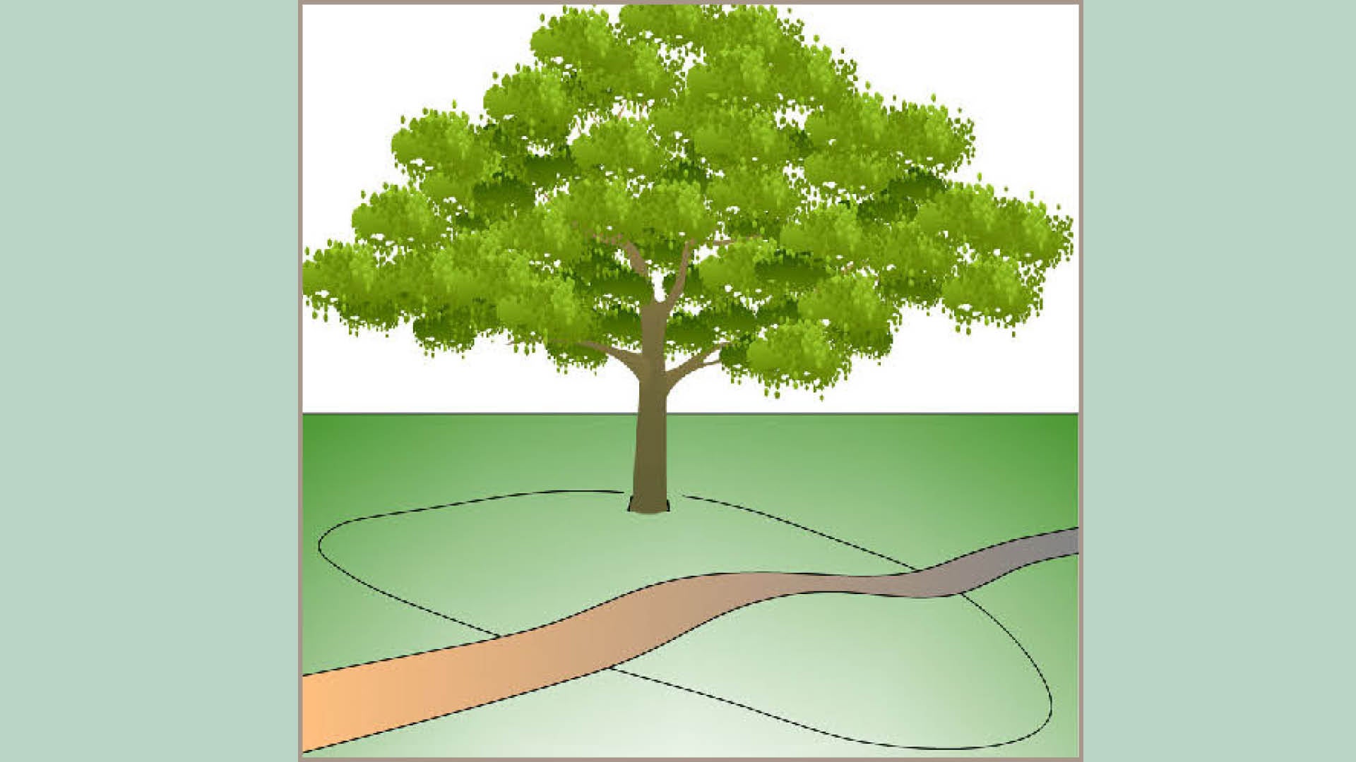
Split
Pathways that separate and deviate past trees. |
Note: Some of these treatment options may be hazardous to people using wheelchairs and also confusing and disorienting to people who have low vision. Ensure sufficient width (min. 1200 mm) is maintained to allow safe passage of a wheelchair, and also that edges have a minimum 30% luminance contrast with adjacent surfaces.
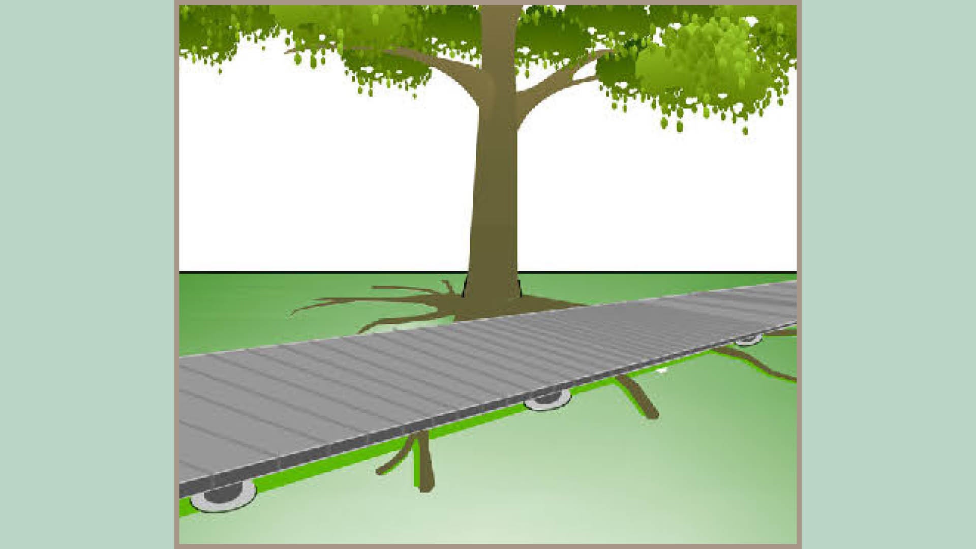
Elevated pathways

Where options for realignment are limited, sensitive footpath design and construction techniques can be used to avoid or lessen tree impacts by minimising the amount of soil disturbance that occurs.
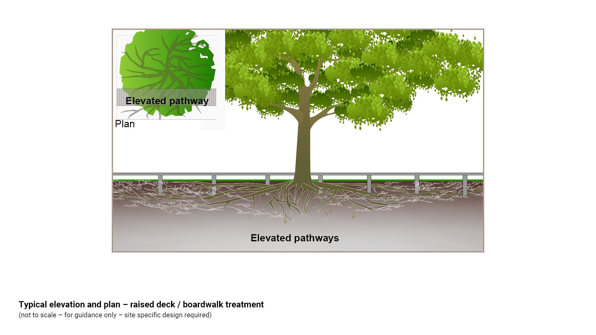
Elevated pathways are designed to minimise soil disturbance, allowing for continued oxygenation of the soil, preservation of soil structure, continued access of roots to water and soil nutrients (if a permeable surface treatment is used, which is highly desirable) and room for continued growth of tree roots without the risk of damage to infrastructure over time.
See Figure 4: Typical elevation and plan – raised deck/boardwalk treatment.
Figure 4: Typical elevation and plan – raised deck/boardwalk treatment
Examples of elevated pathways include, (but are not limited to):

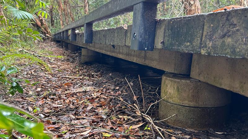
- timber boardwalks (more flexible than concrete)
- concrete boardwalks
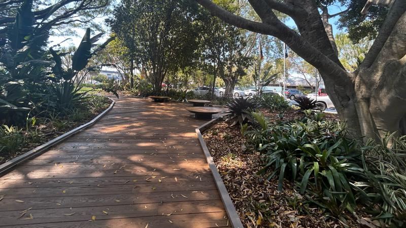
- recycled plastic composite decking (panels and modular decking units)
- bridged (over roots with steel plates/sleepers) footpaths.
See also Table 3: Typical raised pathway treatments.
See Table 3: Typical raised pathway treatments
Example illustration | Treatment description |
|
Timber boardwalks |
 |
Concrete boardwalks |
 |
Recycled plastic composite decking (panels and modular decking units) |
 |
Bridged (over roots with steel plates/sleeper footpaths) |
Note: Systems with small diameter and flexible pier locations are preferable. Piers can be vacuum excavated or hand-dug in order to avoid or minimise damage to tree roots.
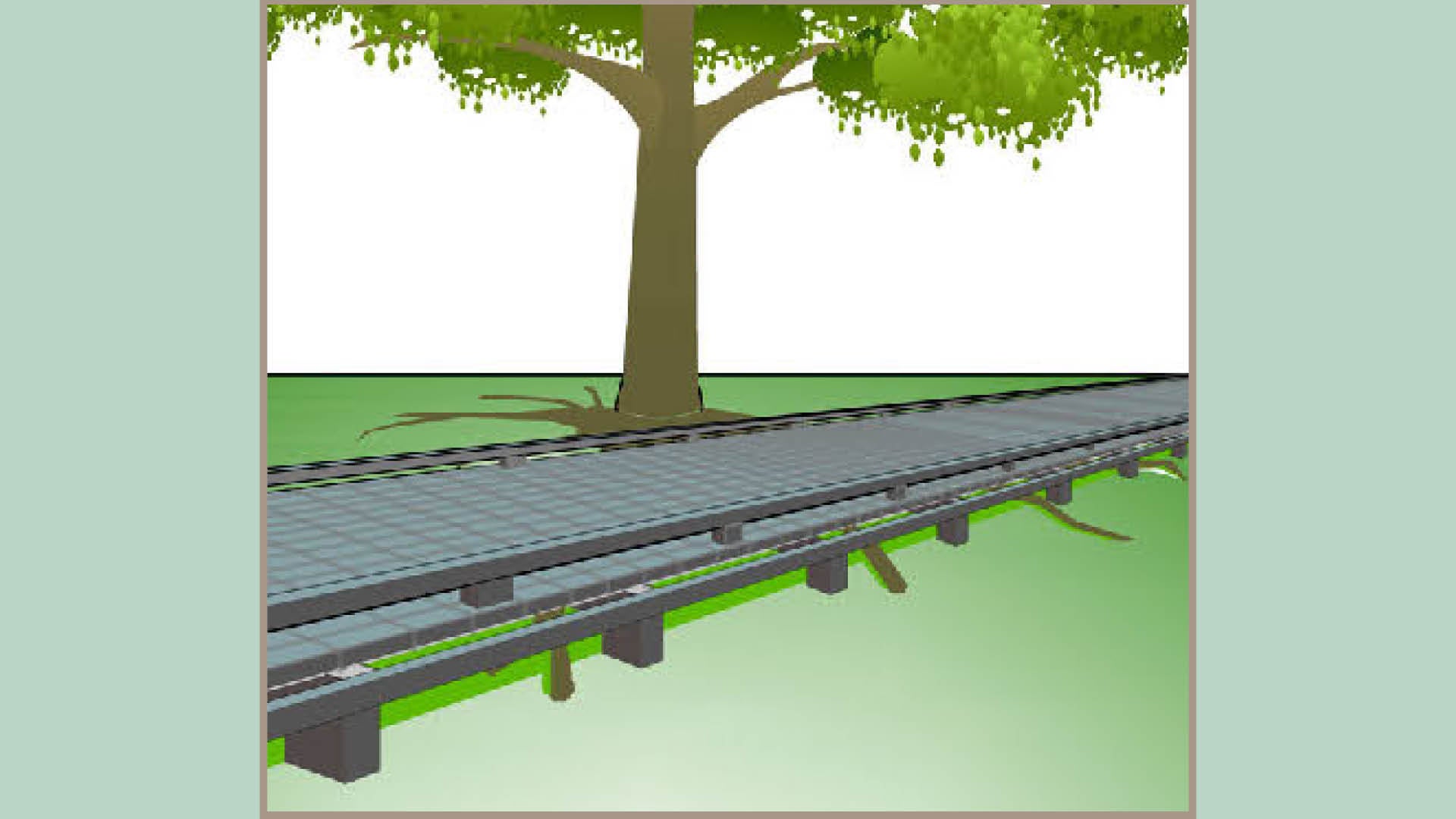
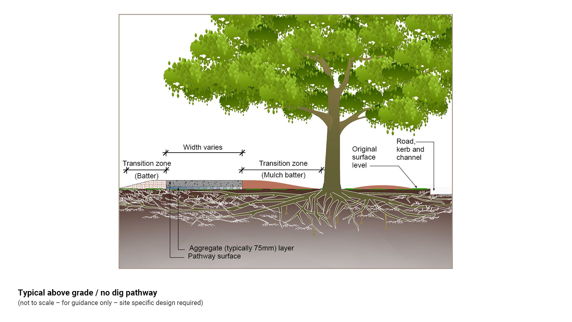
Above-grade pathways ('no dig')
Where elevated pathways/decks are considered cost prohibitive, above-grade or 'no dig' pathways are effective at reducing the extent of soil disturbance by avoiding creation of an excavated sub base.
Raised pathways:
- prevent direct root loss by creating an above grade base for the pathway rather than a traditional below grade one.
- avoid or reduce compaction and therefore attempt to preserve soil structure.
Where a permeable surface is used, these treatments can also ensure continued access of tree roots to water and oxygen.
'No dig' pathways generally have an aggregate sub-base. They may also include a geofabric layer to separate the aggregate from soil layer.
Material choices for the construction of above grade pathways should take into consideration the following:
- adjoining or adjacent pathway construction material
- tree age and condition
- existing conditions of the site/soils
- remaining permeable space.
Due to the height of the construction edge treatments, room for batters also need to be considered. Batters can impact tree health if oxygen flow is impeded. Ideally batters should be no greater than 200 mm depth within TPZs and should not be compacted.
Generally the treatment will only be required for the section of pathway directly adjacent to the tree in question. There should also be enough length in the raised sections of pathway so that the ramps on either end comply with access requirements.
Note: A minimum 1 in 4 grade batter may be required for mowing purposes. If a batter is not suitable for the site, a handrail or kick rail may be bolted to pathway.
See Figure 5: Typical above grade/no dig pathway.
Figure 5: Typical above grade/no dig pathway
Permeable surface treatments for above grade pathways
Permeable pathway treatments can provide a tree with ongoing access to water and direct urban run-off away from the storm water network.
Examples of permeable surface treatments may include, (but are not limited to) the following:
- Open graded (porous) asphalt
- Porous or permeable concrete (no fines concrete)
- Porous stone or porous concrete pavers (the paver itself is permeable)
- Block pavers with porous joints (the voids between pavers are permeable) for example concrete grid
- Interlocking pavers (units with open permeable spaces between them)
- Stabilised decomposed granite
- Bound recycled glass porous pavement.
Note: In retrofit scenarios, all bases must be above ground to protect tree roots. Permeable surfaces are only successful when installed without any excavation adjacent to existing trees
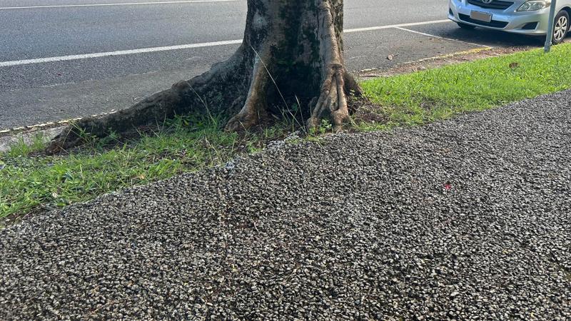
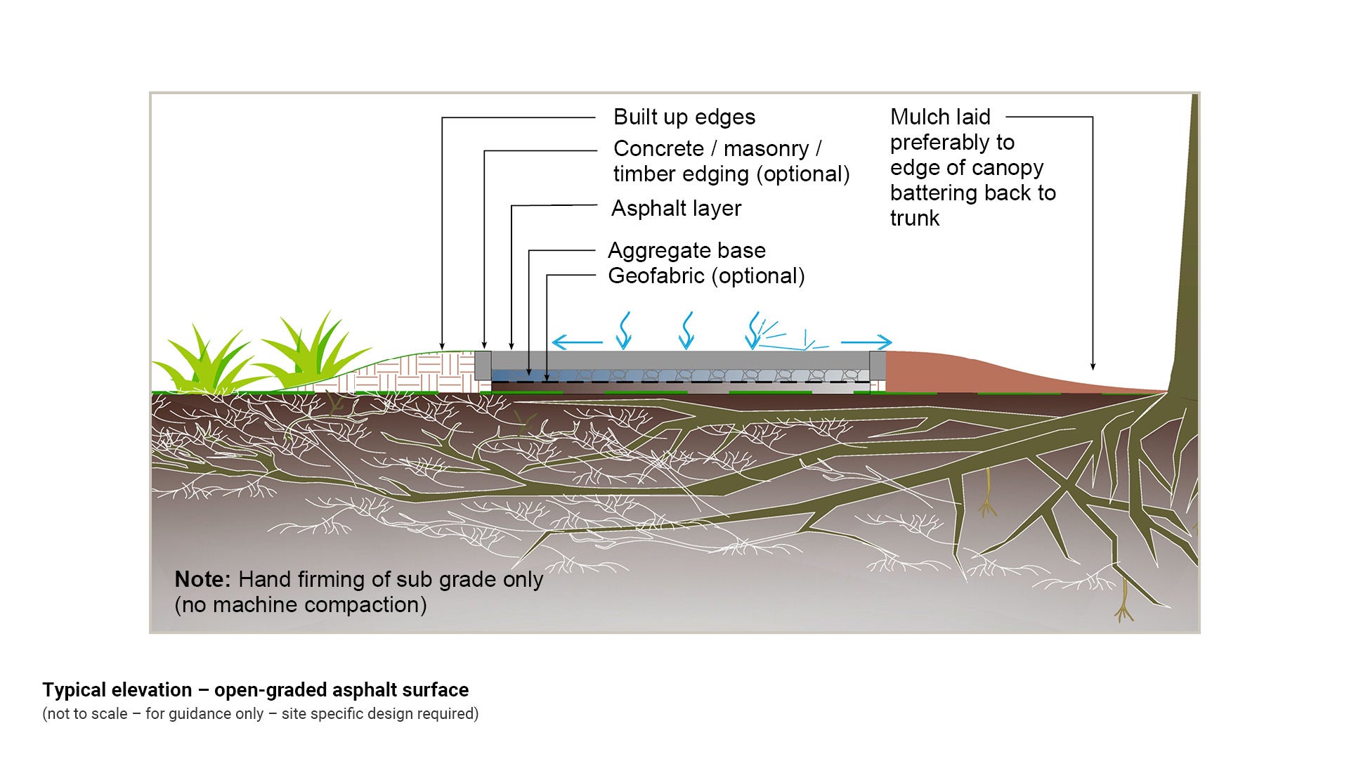
Open-graded asphalt surface
Asphalt pathways move and flex with tree roots, and are less prone to cracking than concrete pathways. Cracks that do occur can be easily repaired.
- Sub grade is to be hand firmed only (no machine compaction)
- Aggregate base of typically 75 mm
- May include geofabric layer to separate aggregate from soil layer
- Optional edging for asphalt pathway - timber, masonry, concrete
- Build up edges to form batters on far side of path from tree. Ideally, these batters should be no greater than 200 mm deep in TPZs, and consist of a porous material
- Mulch laid on near side to tree - battering down to natural grade at the trunk.
See Figure 6: Typical elevation - open-graded asphalt surface.
Figure 6: Typical elevation - open-graded asphalt surface
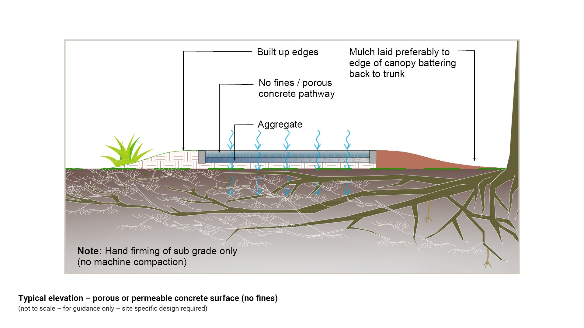
Porous or permeable - concrete surface (no fines)
No fines concrete is made without fine aggregate (including sand) in the mix, producing a surface with high permeability and drainage capacity.
- Sub grade is to be hand firmed only, with no machine compaction
- Aggregate base of typically 75 mm
- May include geofabric layer to separate aggregate from soil layer
- Build up edges to form batters on far side of path from tree. Ideally, these batters should be no greater than 200 mm deep in TPZs, and not compacted
- Mulch laid on near side to tree - battering down to natural grade at the trunk.
See Figure 7: Typical elevation - porous or permeable concrete surface (no fines).
Figure 7: Typical elevation - porous or permeable concrete surface (no fines)
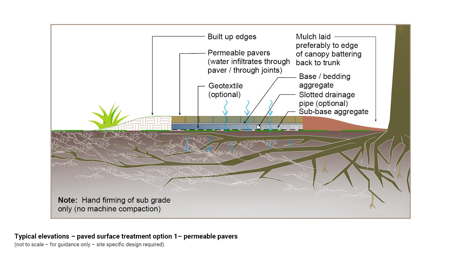
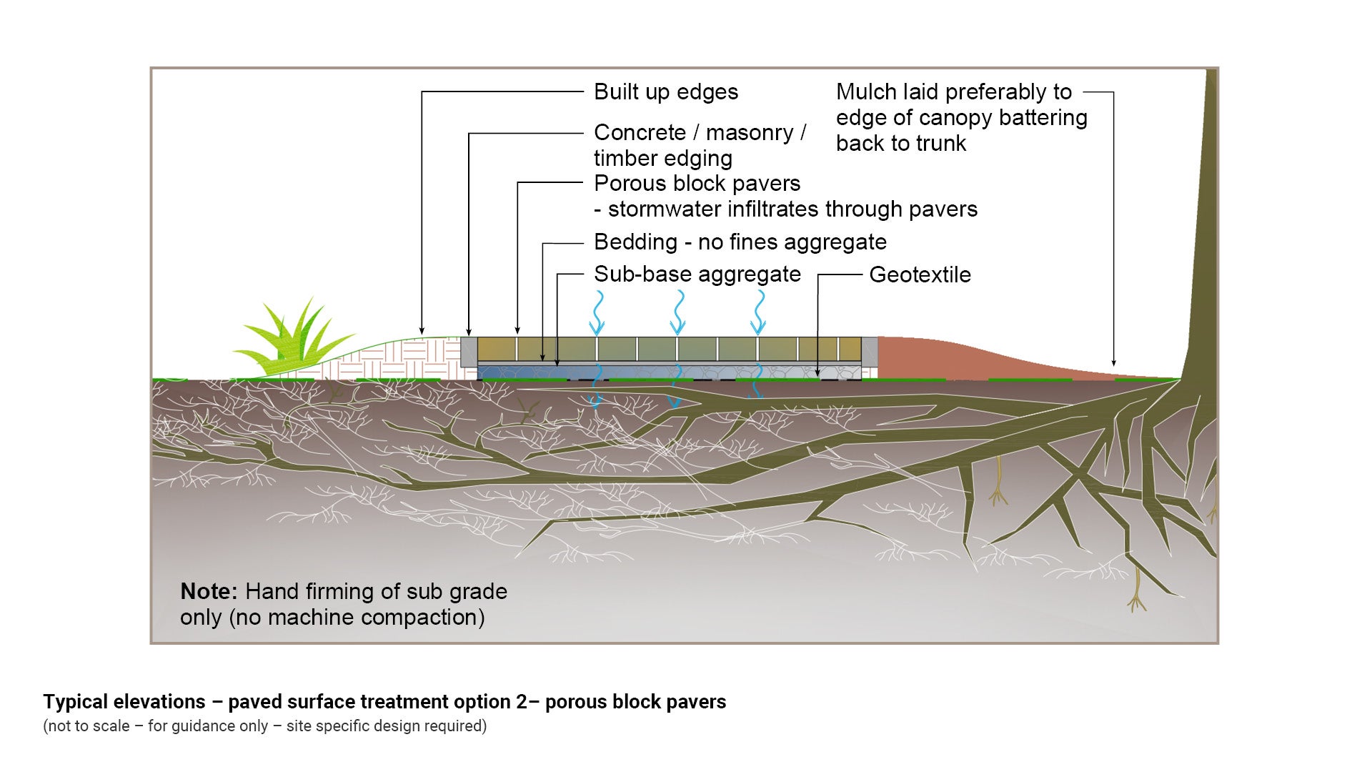
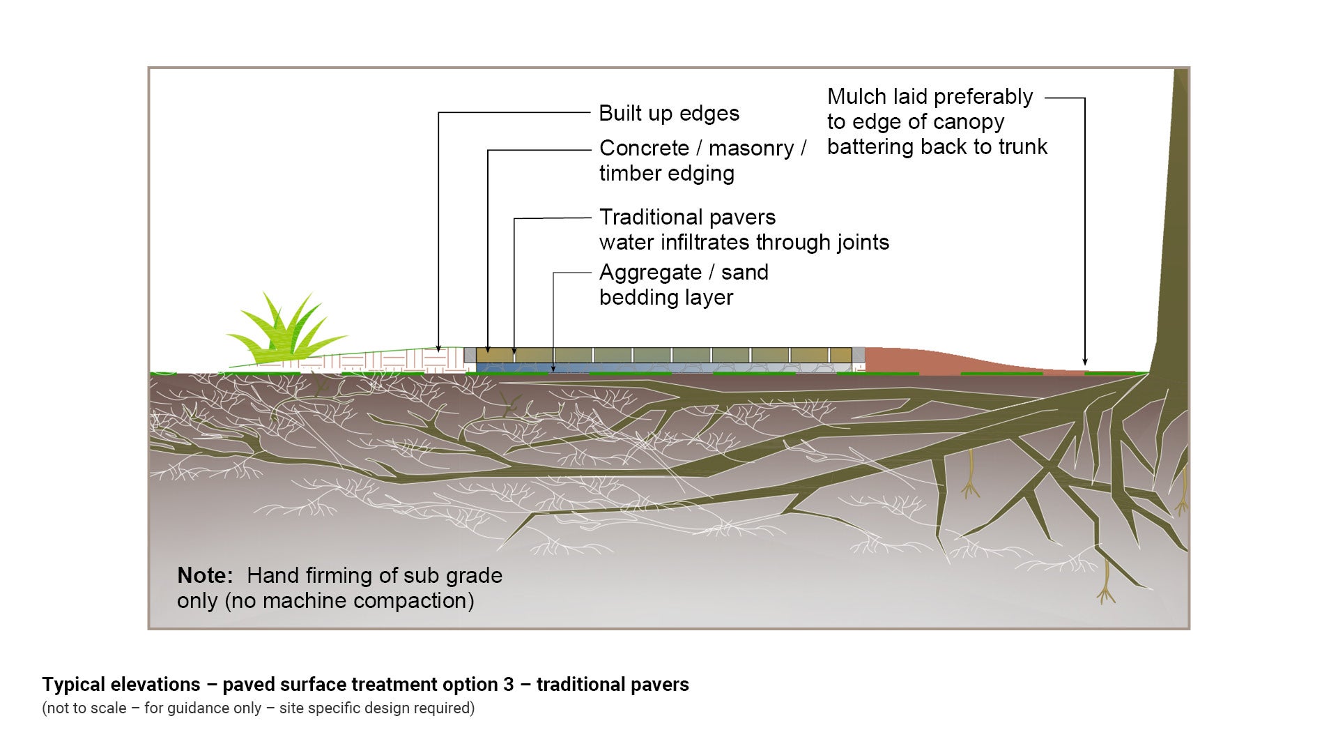
Porous or permeable paving
Paved pathways can be used to allow water to infiltrate to roots either through permeable pavers, the joints between traditional pavers, or a combination of both:
- Sub grade is to be hand firmed only (no machine compaction)
- Aggregate base of typically 75 mm.
- May include geofabric layer to separate aggregate from soil layer
- Build up edges to form batters on far side of path from tree. Ideally, these batters should be no greater than 200 mm deep in TPZs, and not compacted
- Mulch laid on near side to tree - battering down to natural grade at the trunk.
See Figure 8: Typical elevations - paved surface treatment options.
Figure 8: Typical elevations - paved surface treatment options
Permeable pavers
Porous block pavers
Traditional pavers
Above grade load supporting systems
A number of additional products have been designed to provide above-ground rather than below grade load support to vehicles.
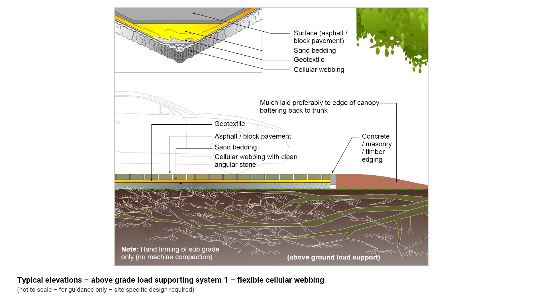
Cellular webbing ('no dig')
Cellular webbing or geogrids are made from a geosynthetic material and can be filled with gravel for an open porous treatment or can be filled with stone and capped with asphalt or pavers for a closed porous treatment.
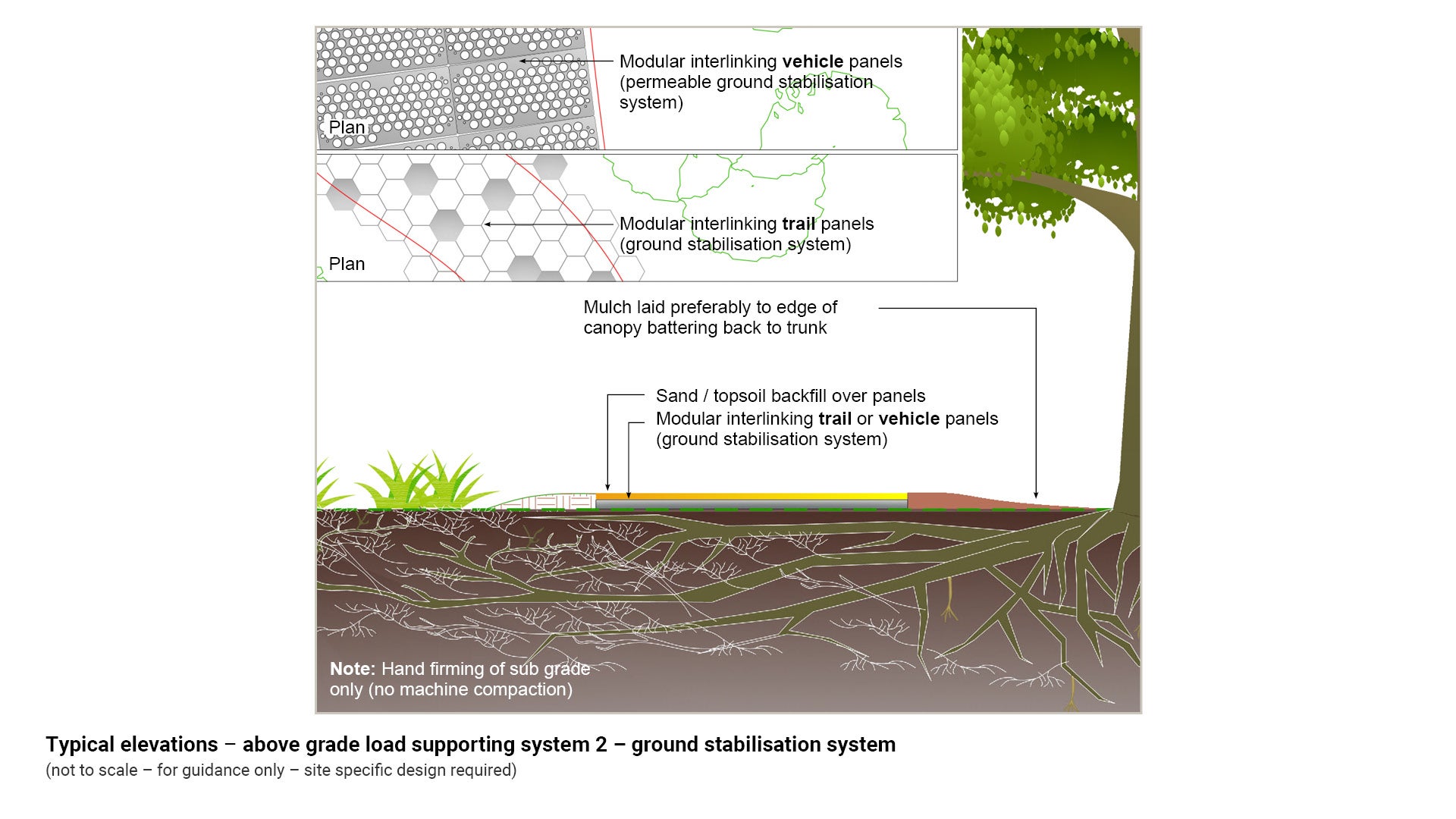
Ground stabilisation systems
Ground stabilisation systems in the form of inter-linking panels, also provide above grade load support and can be utilised adjacent to existing trees where no-dig ground reinforcement is required.
See Figure 10: Typical elevations - above grade load supporting systems.
Figure 10: Typical elevations - above grade load supporting systems
Flexible cellular webbing (above ground support)
Ground stabilisation system
Treatments to extend the life of above grade pathways
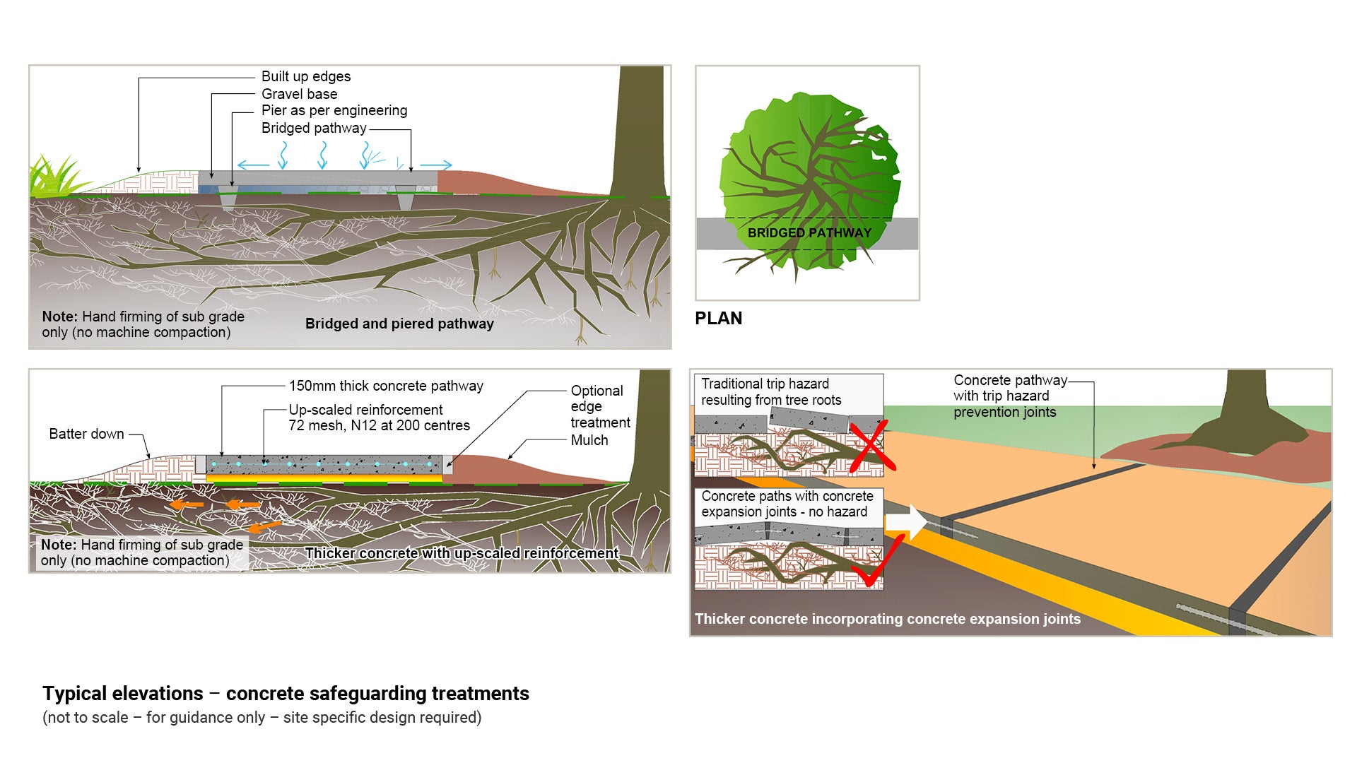
Where a concrete surface must be used, a range of additional treatments can be enlisted to protect these above grade pathways from the force of root heave from beneath. These include:
- securing pathway with piers
- using thicker concrete and increasing/up-scaling reinforcement
- incorporating concrete expansion joints.
Pier
Piered or pinned concrete pathways are effective for bridging over tree roots.
Thicker concrete and up-scaled reinforcement
Thicker concrete and up-scaled reinforcement can help to safeguard the useful life of a pathway by strengthening it.
Incorporating concrete expansion joints
Specialised footpath joints have been developed to prevent footpath displacement when lifted due to pressures from tree roots. These products safely accommodate movement at the joints without the development of trip hazards. For further guidance, refer to IPWEA Standard Drawing RS-065 - Concrete Pathway Construction Details.
See Figure 10: Typical elevations - concrete safeguarding treatments.
Figure 10: Typical elevations - concrete safeguarding treatments
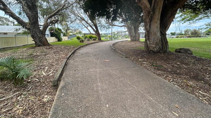
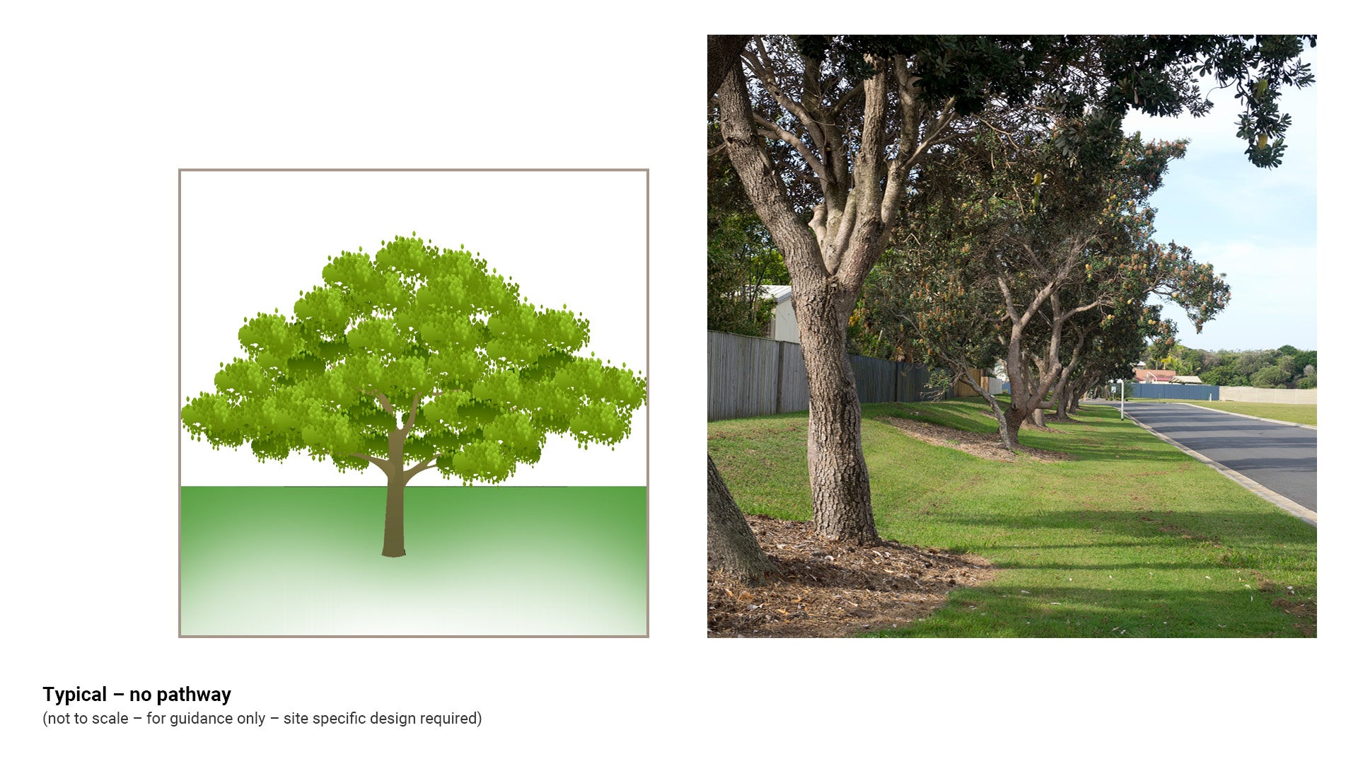
No pathway
Where a significant risk of damage has been identified, and no alternative treatment solution is viable, consideration should be given to whether a pathway is necessary at all. This may involve a grassed area, mown regularly.
In this aesthetically pleasing option, there is no soil disturbance, no risk of root damage and continued access of tree roots to air, water and nutrients.
See Figure 11: Typical - no pathway.
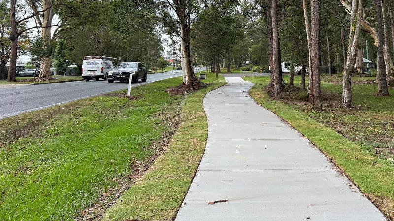
Figure 11: Typical - no pathway
This component is currently in development