Tactiles
Design
Requirements for the design, manufacture and installation of embellishments
Good design
See the following corporate documents to identify relevant project design requirements:

Sunshine Coast Planning Scheme regulates the way land, buildings and structures are used and developed on the Sunshine Coast.

Sunshine Coast Design contains 10 design principles that guide good project planning and design outcomes, that are appropriate for the Sunshine Coast.
The LIM provides further overarching design advice, refer:
- Introduction and Design Principles - e.g. sustainability, CPTED, accessibility
- Preliminaries - environmental management, tree sensitive design and site set up.
Embellishment requirements
- Universal access.
- Comfortable and suitable for the average person.
- See 'Positioning' and 'Equal access' sections for the corresponding LIM category.
- Made from materials that will be durable and can be suitably protected from exterior elements, such as salt spray and UV exposure.
- Robust and sturdy to withstand constant public use and be resistant to vandalism.
- Fixings are to be 316 marine grade stainless steel (unless otherwise stated).
- Tamper proof fixings should be used
- Graffiti protection coatings applied (where applicable)
- Fire retardant (where applicable).
- Warranties should be as listed below.
- Easily repairable or replaceable.
- Sourced locally and use standard fittings.
- Reputable suppliers should be used who keep a supply of stock parts on hand for the life of the product.
- Use sustainable materials, although sustainability needs to be considered over the lifetime of the embellishment.
- Install on paved, concrete or other hard surfaces (where applicable).
- Manufactured to engineering specifications (where applicable).
- See the 'Standards' section for the corresponding LIM category.
Warranty and asset life
Product/embellishment | Warranty (minimum) | Asset life (typical useful life) |
Ceramic tactiles | 10 years | Not available |
Concrete/concrete polymer tactiles | 10 years | Not available |
Fibre reinforced polymer tactiles | 2 years | Not available |
Rubber/synthetic rubber tactiles | 2 years | Not available |
Plastics tactiles | 2 years | Not available |
Natural/reconstructed stone tactiles | 10 years | Not available |
Stainless steel tactiles | 10 years | Not available |
Tactile ground surface indicators (TGSI)
Once the location of the tactiles has been decided, based on the Environment and Liveability Strategy (ELS) and Recreation Parks Plan (RPP) guidance, consider the appropriate embellishment level to suit the selected site.
Overarching design considerations:
People who are blind or have vision impairment rely entirely on environmental and sensory clues to navigate footpaths, large open pedestrian spaces and across roads:
- Tactile indicators are designed to provide blind or vision impaired persons (VIPs) with information about orientation by means of haptic (tactile) perception, in combination with usable vision. Most people who are legally blind have some usable vision.
- Haptic perception is the process of recognising objects through sense of touch.
- A person’s orientation comes about by processing all available environmental cues, making the information provided by the TGSI meaningful.
- Luminance contrast is the difference in the amount of light reflected from the TGSI compared to the amount of light reflected from the surrounding surface.
- Slip resistance is enhanced by a textured design on the top of the dome (warning TGSI) and on the horizontal base surface of the unit (warning and directional TGSI).
Hazard or warning TGSI

TGSI’s are available in ‘hazard’ (warning) type:
- hazard or warning TGSIs indicate an approaching hazard but not what the nature of the hazard will be.
- where there is a potential hazard, the intended message is to stop, consider and wait before proceeding.
Directional TGSI
TGSI’s are available in ‘directional’ type:
Where direction is required through a space or between areas, the intended message is that it is okay to proceed along the indicated path of travel.
- avoid installing directional TGSI unless:
- there is an absence of other cues such as kerb lines.
- distance from a building line to a hazard is greater than 3.0 m.
Design of TGSIs
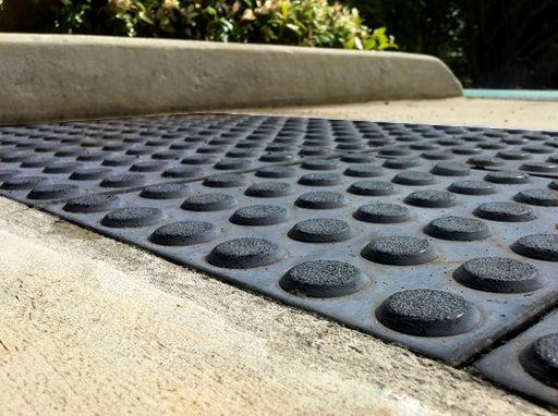
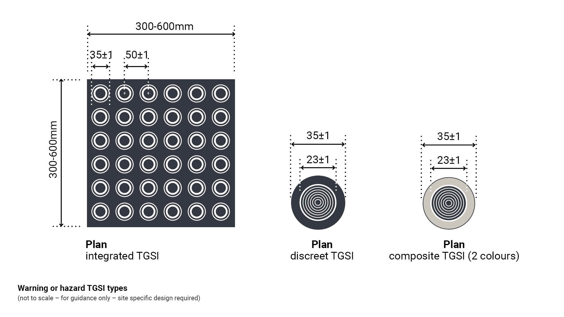
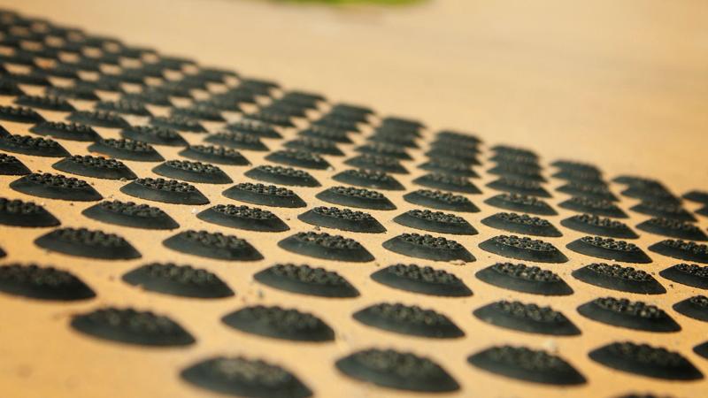
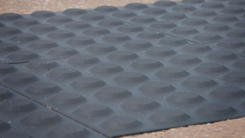
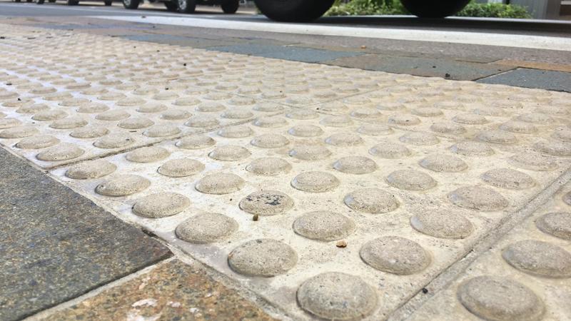
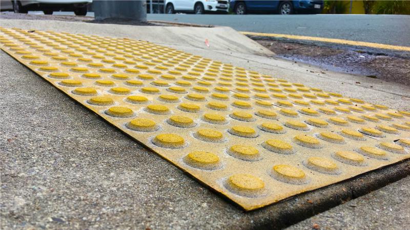
Warning or hazard TGSI
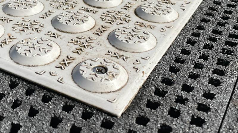
Hazard TGSI are a defined pattern of raised truncated cones which may be in the form of integrated tiles, discrete units or composite units.
- These devices inform a person who is blind or has low vision to stop 300 mm from a potential hazard, risk or point of information; to determine which of these it might be and then to make a decision about whether to proceed or move away from the area that has been identified.
- The area of treatment should always be a place where it is safe to stand whilst discerning the information that is being provided.
See Figure 1: Warning or hazard TGSI types.
Figure 1: Warning or hazard TGSI types
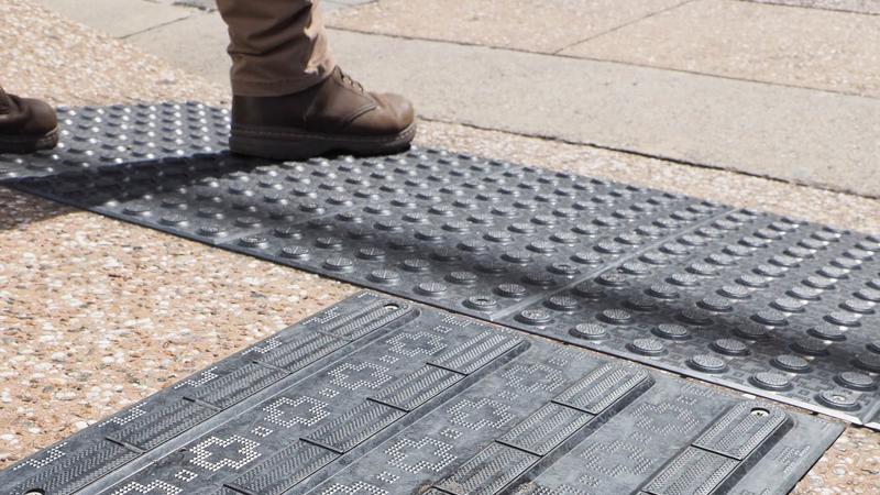
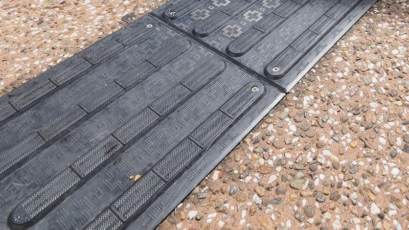
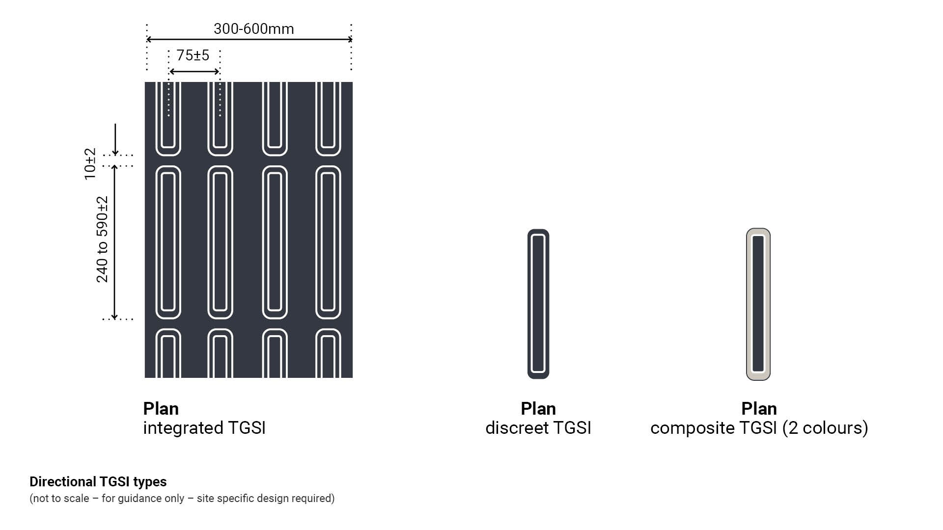
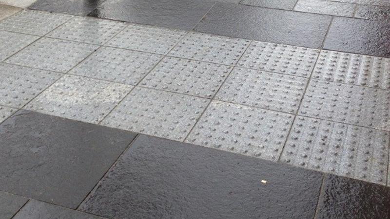
Directional TGSI
Directional TGSI are a defined pattern of elongated raised nodules which may be in the form of integrated tiles, discrete units or composite units.
- Their purpose is to provide way finding advice for a person with low vision or a person who is blind, about the direction of safe travel through a space or to an object or service.
- Directional TGSI provide the opportunity for a person who navigates using a white cane, to pass the circular end of the cane along the direction of the tactile grooves, ensuring the person stays along the safe path of travel.
See Figure 2: Directional TGSI types.
Figure 2: Directional TGSI types
Unit types of TSGIs
Integrated units
A tactile ground surface indicator comprising a series of raised cones (warning), or elongated bars (directional), merged into a backing plate.
Discrete units
Separate raised cones or elongated bars of one colour and material which require a drilling template to ensure they are set out at the required spacings.
Composite units
Separate raised cones or elongated bars constructed from one material for the sloped section, and a different material for the upper flat section.
See the following for further guidance:
- Table 1: Warning TGSI types
- Table 2: Directional TGSI types.
Table 1: Warning TGSI types
Product type | Characteristics | Key considerations/ recommendations |
Integrated units 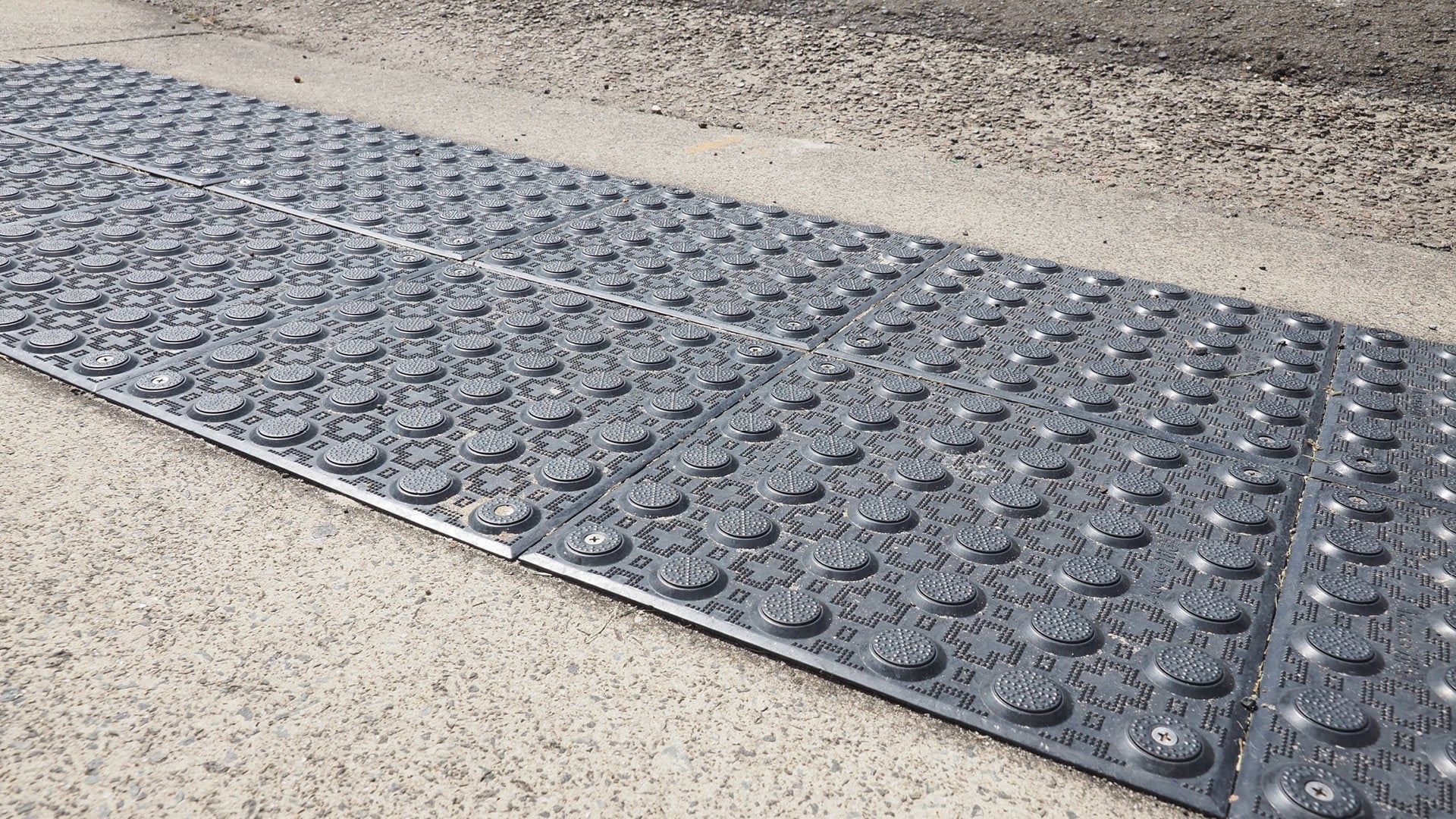 |
| Good solution - suitable for use.
May be retro fitted (glued and screwed) - Integrated units are the preferred solution for existing sites. May be set into new concrete - Integrated units are the preferred solution for new sites. |
Discreet units 
|
| NOT preferred due to short life and lifting of individual cones and strips. NOT SUITABLE FOR USE
|
Composite units 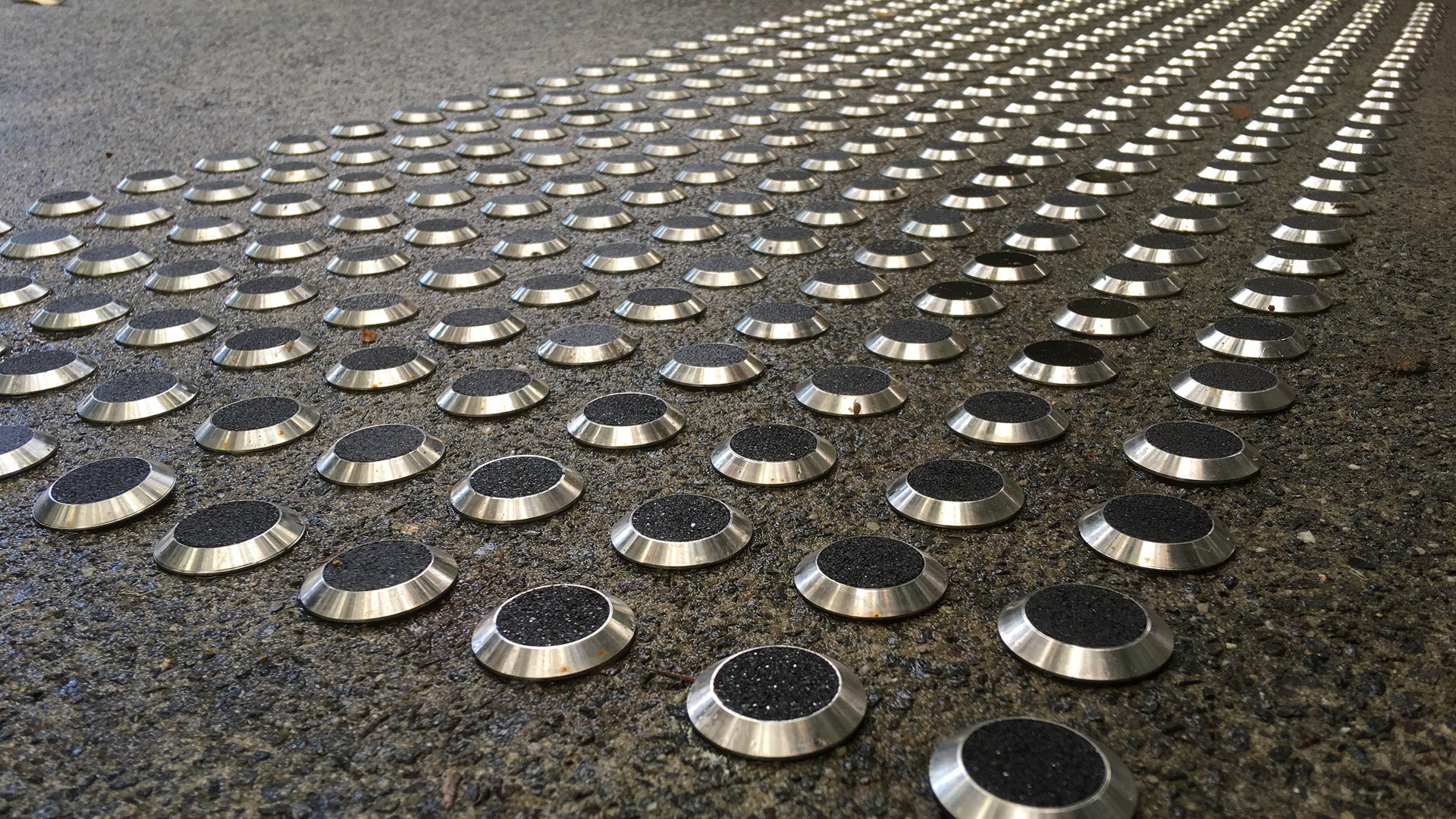 |
| NOT preferred due to lifting of individual cones and strips. NOT SUITABLE FOR USE
|
Table 2: Directional TGSI types.
Product type | Characteristics | Key considerations/recommendations |
Integrated units 
|
| Good solution - suitable for use.
May be retro fitted (glued and screwed) - Integrated units are the preferred solution for existing sites. May be set into new concrete - Integrated units are the preferred solution for new sites. |
Discreet units 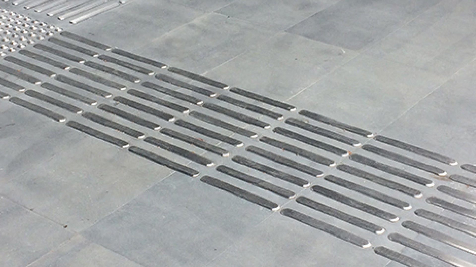 |
| NOT preferred due to short life and lifting of individual strips. NOT SUITABLE FOR USE
|
Composite units 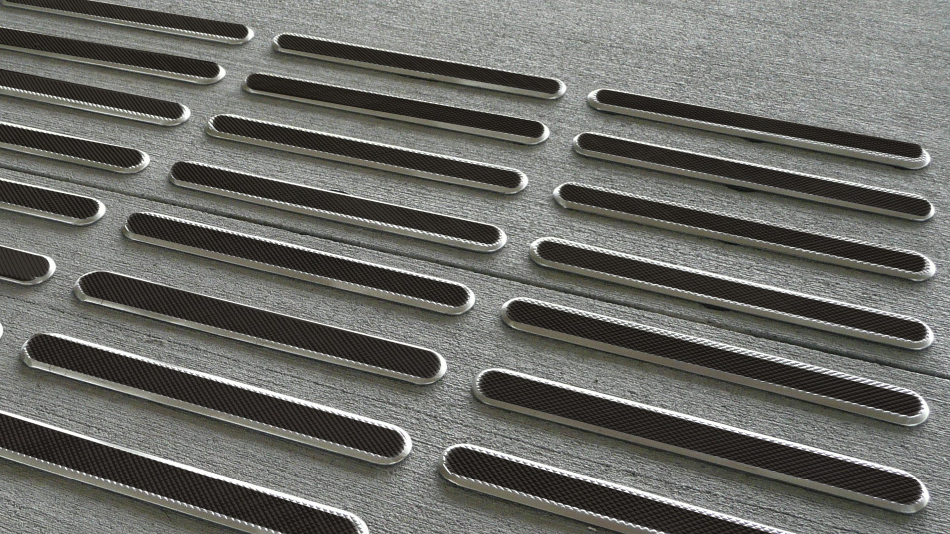 |
| NOT preferred due to lifting of individual strips. NOT SUITABLE FOR USE
|
Material types for TGSIs
TGSIs are available in a variety of materials ranging from porcelain and concrete to rubber, plastic, metals, and fibre composite materials.
Cast on place porcelain units are preferred for new builds in parks and open spaces. They require surface preparation which can be undertaken while an area is under construction. A recess is created for insetting the TGSI into the surface material.
Materials such as surface applied polymer, rubber or plastic are suitable for retro-fit to existing surfaces. Surface applied polymer units are screwed down and glued. Other materials require surface bonding by adhesive onto the surface material.
TGSI are to be made from:
- Robust materials that are vandal and corrosion resistant (particularly in coastal areas):
- suitable for the coastal corrosive environment
- suitable for use in the public open space environment.
- manufactured to engineering specifications (where applicable).
TGSI products and materials are to be:
- Guaranteed UV resistant (minimum 5 years).
- Guaranteed slip resistant (in accordance with AS 4586 – slip resistance to cover TGSI dome and base).
- ‘wet pendulum test’ assessment group = W or better.
- ‘ramp test’ assessment group = R11 or better.
- Designed compliant with AS 1428.4.1:2009 (for size and spacing).
- Installed so that edges do not lift.
- Installed so that individual discrete buttons do not lift. (Individual discrete buttons are not a preferred option).
Preferred materials
Select a TGSI which is inset and/or mechanically (fixed) and chemically (glued) to prevent lifting, such as:
- Porcelain integrated tiles set into concrete are to be used in high pedestrian traffic areas which are not subject to vehicles crossing over and are not in near vicinity to a road.
- High specification precast reinforced concrete is recommended where vehicles will come into contact with the TGSI.
- Fibre reinforced polymer surface applied integrated pads, fixed and glued to pedestrian areas, especially high use areas which may be subject to vehicles crossing over (such as at kerb ramps).
- Fully cast TGSI are preferred over two part TGSI (where the top is glued on).
- For instances where the application warrants a different product, approval from the relevant Council department must be obtained.
TGSI materials have individual strengths, weaknesses and varying aesthetic appeal:
- Select a TGSI material which is compatible with the substrate that the TGSI is to be applied to.
- Plastic stick on TGSI may be appropriate for temporary retro fit locations due for complete refurbishment, and where tactiles coincide with service pit lids.
- Consult an access consultant accredited by Association of Consultants in Access Australia Inc. (ACAA) for site specific advice.
TGSI material types are shown in order of preference, see the following for further guidance and application information. The tables information is shown in order of preference and application.
- Table 3: TGSI materials (preferred)
- Table 4: TGSI materials (NOT preferred).
Ceramics (porcelain)
Ceramics are inorganic materials made from compounds of a metal and a non-metal. Porcelain is a ceramic material made by heating materials (generally including clay) in a kiln at high temperatures. The result is strong, hard, stiff and brittle. Ceramic tactiles must have a minimum breaking strength of 1100N, tested in accordance with AS 4459 – Methods of sampling and testing ceramic tiles. (N) Newtons equal a unit of force required to accelerate a mass of one kilogram, one metre per second.
- When a vehicle passes over a rigid TGSI, the vehicle load is applied over a small area which can result in cracking.
- Porcelain TGSI are preferred for new builds in parks and open spaces where no vehicular traffic will pass over the tactile.
- Where maintenance vehicles may cross over the tactiles, select an alternative to porcelain.
Concrete
Concrete TGSI are made from combined broken stone or gravel, sand, cement and water, which are poured into moulds to form a stone-like mass when hard.
- Concrete TGSI are to be made from high strength concrete. Colours are to be made from UV resistant oxides.
- Manufacturers recommend surface treatment (sealing) of concrete tactiles with a water-repellent material to preserve the integrity of the tile colour.
- Select a penetrating type sealant that does not reduce slip resistance.
- Select a tinted sealant to enhance luminance contrast.
- Concrete TGSI 40 mm thick are preferred for high use pedestrian areas which are separated from roadways.
- The tactile is to be inset and laid with a 10 mm gap for grout. In precinct areas grout colour is to match the pavers.
- The darkest oxide available is recommended for the majority of pavements.
- For timber applications the preferred method is a 40 mm concrete TGSI set into a concrete tray for longer life.
- High specification pre-cast reinforced concrete is recommended where vehicles will come into contact with TGSI.
Concrete polymer (not preferred)
Fibre reinforced concrete contains short discrete fibres which increase the structural integrity of the concrete. The result is a flexible tile.
The TGSI is about 10 mm thick at the base and recessed into the path of travel to achieve 5.0 mm tactile projections. Fixed with regular tile adhesive with a 2.0 mm – 3.0 mm grout spacing between tiles.
Fibre reinforced polymer
Polymer TGSI are made from various chemical compounds, fibre reinforced, UV stabilised, linked together to form a polymeric compound. Textured design on the domed surface and horizontal base surface is designed to reduce the risk of slipping.
- Surface applied polymer TGSI are mechanically and chemically affixed to a stable existing surface.
- Mechanical connection is provided by nylon composite, corrosion resistant anchors and 304 stainless steel fasteners.
- A high quality adhesive polymer is added to the bottom of the base surface.
- Inset polymer TGSI are applied during the curing of wet concrete. Once the concrete cures, the unit is mechanically fixed to the surface or substrate.
- Corrosion resistant nylon composite hexagonal anchors and counter sunk tamper proof 304 stainless steel fasteners provide mechanical connection between the TGSI and the substrate.
Rubber/synthetic rubber

Rubber is a tough elastic substance formed from the latex of a tropical plant or made synthetically using petroleum.
Synthetic rubber TGSI are about 2.0 mm thick at the base with a 5.0 mm tactile projection. Units may be fixed in place using a polyurethane adhesive or can be supplied with a pre-applied adhesive backing.
- Rubber is recyclable and fireproof.
- Only to be used on flexible surfaces such as asphalt where screws will not hold.
- Suitable for a temporary application which is due for complete refurbishment.
Plastics
There are 2 types of plastics used to create TGSI
- Polyurethane
- Thermoplastic polyurethane acrylic (TPU).
Polyurethane
Plastics (polyurethanes) are formed from an alcohol and two or more reactive hydroxyl groups, with catalysts and additives.
- Polyurethane integrated units are installed directly onto an existing substrate.
- Tiles are 2.0 mm thick at the base with 4.7 mm tactile projections and may be fixed with double sided rubber (in a roll form 1.0 mm thick).
- Discrete units are fixed into drilled or saw-cut holes.
- Polyurethane flexible TGSI may be suitable for retro-fit to an existing surface that:
- is subject to movement
- where there are existing service lids with irregular finishes.
Thermoplastic polyurethane acrylic (TPU)
Plastics (Thermoplastic polyurethane acrylic - TPU) is formed from an alcohol and two or more reactive hydroxyl groups, with catalysts and additives.
- TPU discrete units are installed into drilled or saw-cut holes.
- Surfaces are durable with a high abrasive resistance.
Natural stone/reconstructed stone
Granite is a hard igneous rock (formed by the cooling and solidifying of molten material) consisting mainly of quartz, mica and feldspar. TGSI made of solid natural granite are about 35 mm at the base with 5.0 mm tactile projections. Granite TGSI require an inset installation.
- TGSI can be custom made from natural stone materials such as granite, marble, sandstone, slate, blue stone, basalt and travertine.
- Discrete inserts are made from granite with an ex-foliated or sand blasted finish.
- Finished thickness is 20 mm to 40 mm.
- No historical data is available.
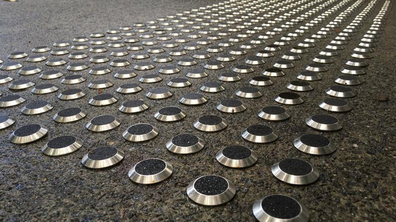
Stainless steel and brass
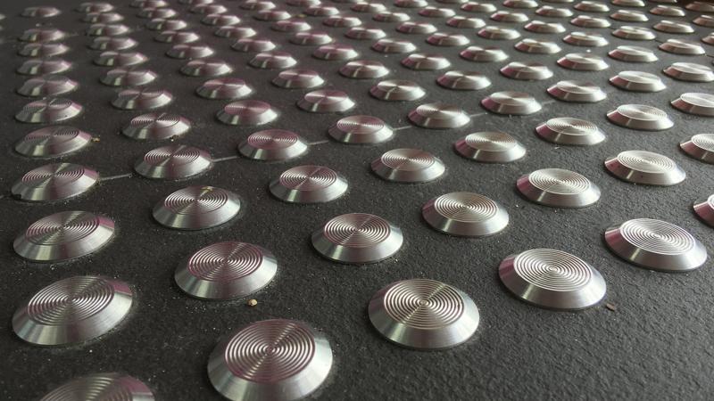
It is not recommended to use stainless steel or brass TGSI for any outdoor application due to reduced slip resistance when wet and because they have the potential to introduce glare when exposed to sunlight.
- Consider that certain eye conditions are extremely sensitive to glare.
- Tiles and discreet units may be screwed in place and are removable.
- Metal TGSI are recommended for inside building applications only.
- Do not use in open spaces.
Table 3: TGSI materials (preferred)
Shown in order of preference and application.
Material and product type | Install method/application and preferred location | Key considerations/recommendations |
Ceramics (Porcelain) Integrated unit 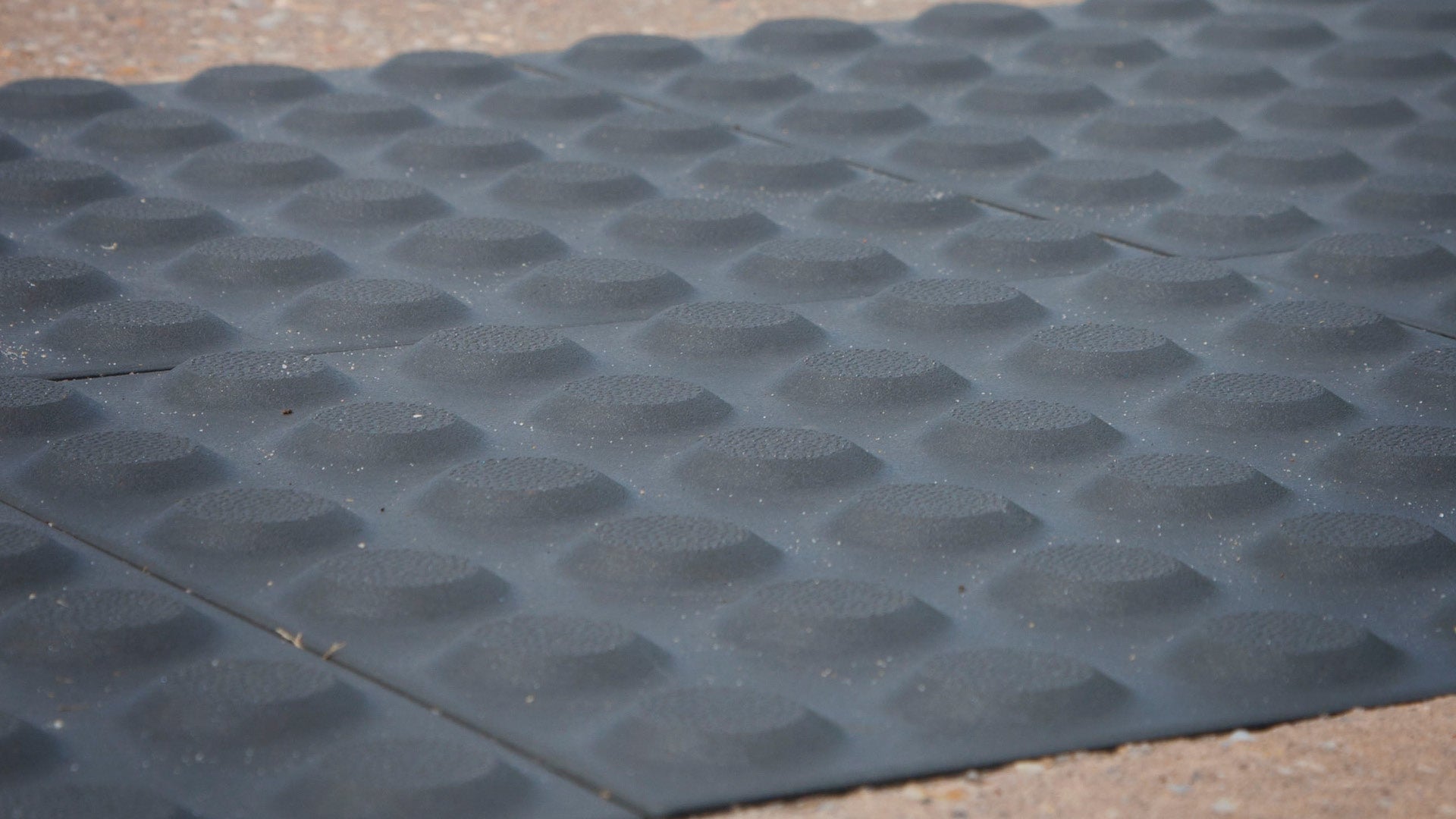 | Install method: Inset
Application: New builds
Preferred location:
|
NOT recommended for sites where vehicles may cross over the tactiles or in close vicinity to roadways. |
Concrete Integrated unit 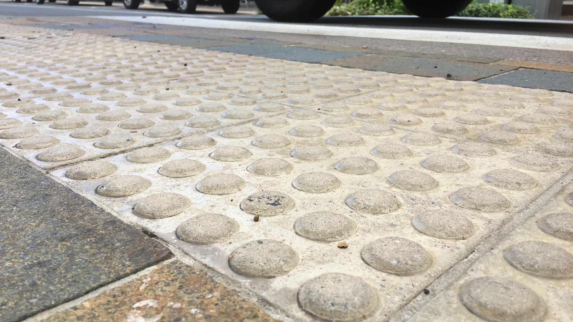 | Install method: Inset
Application: New builds
Preferred location:
|
|
Fibre reinforced polymer (plastic) Integrated unit 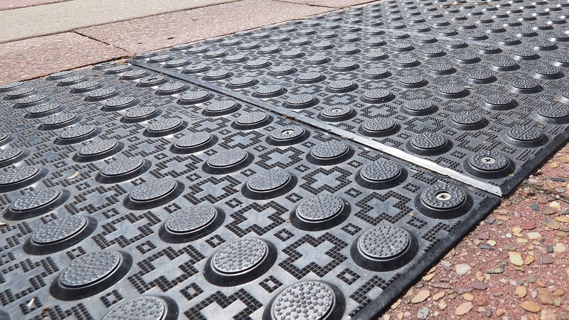 | Install method: glued and fixed OR inset
Application: New builds OR retro-fit
Preferred location:
|
|
Table 4: TGSI materials (NOT preferred)
Shown in order of preference and application.
Material and product type | Install method/application and preferred location | Key considerations/recommendations |
Rubber/synthetic rubber Integrated unit 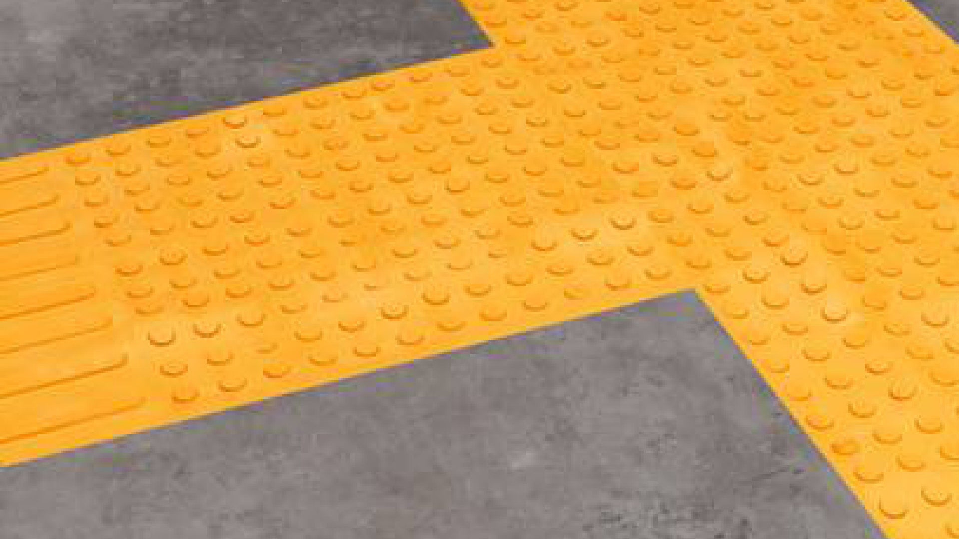 | Install method: stick-on
Application: retro-fit
Preferred location: All temporary locations or service lids.
|
NOT preferred, except where specified for a particular application. |
Plastics Integrated or discrete units 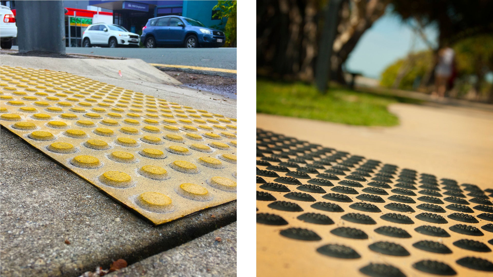
| Install method: stick-on OR drilled or saw-cut, inserted and glued
Application: new builds OR retro-fit
Preferred location: All temporary locations or service lids. |
NOT preferred, except where specified for a particular application. |
Natural/reconstituted stone Integrated units 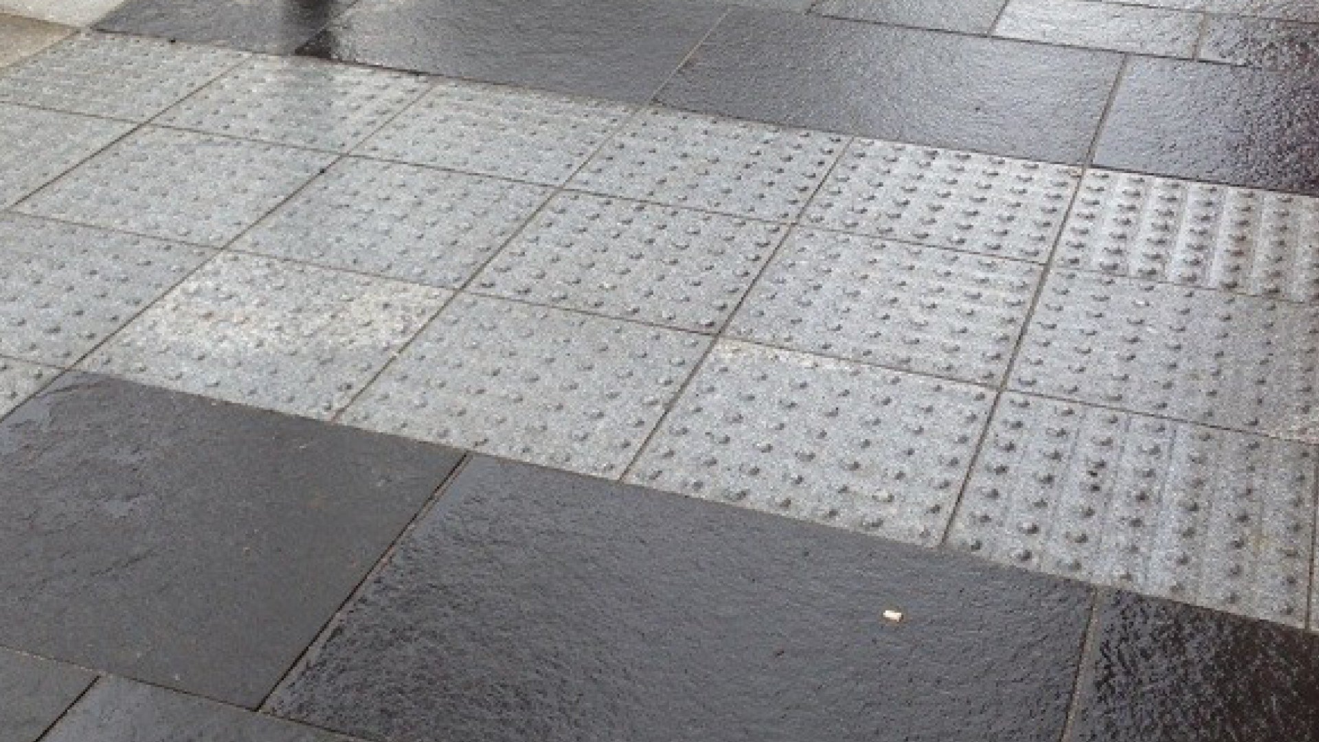 | Install method: inset
Application: new builds
Preferred location: No historical data available. |
NOT preferred, except where specified for a particular application.
|
Stainless steel/brass Integrated units or discrete units 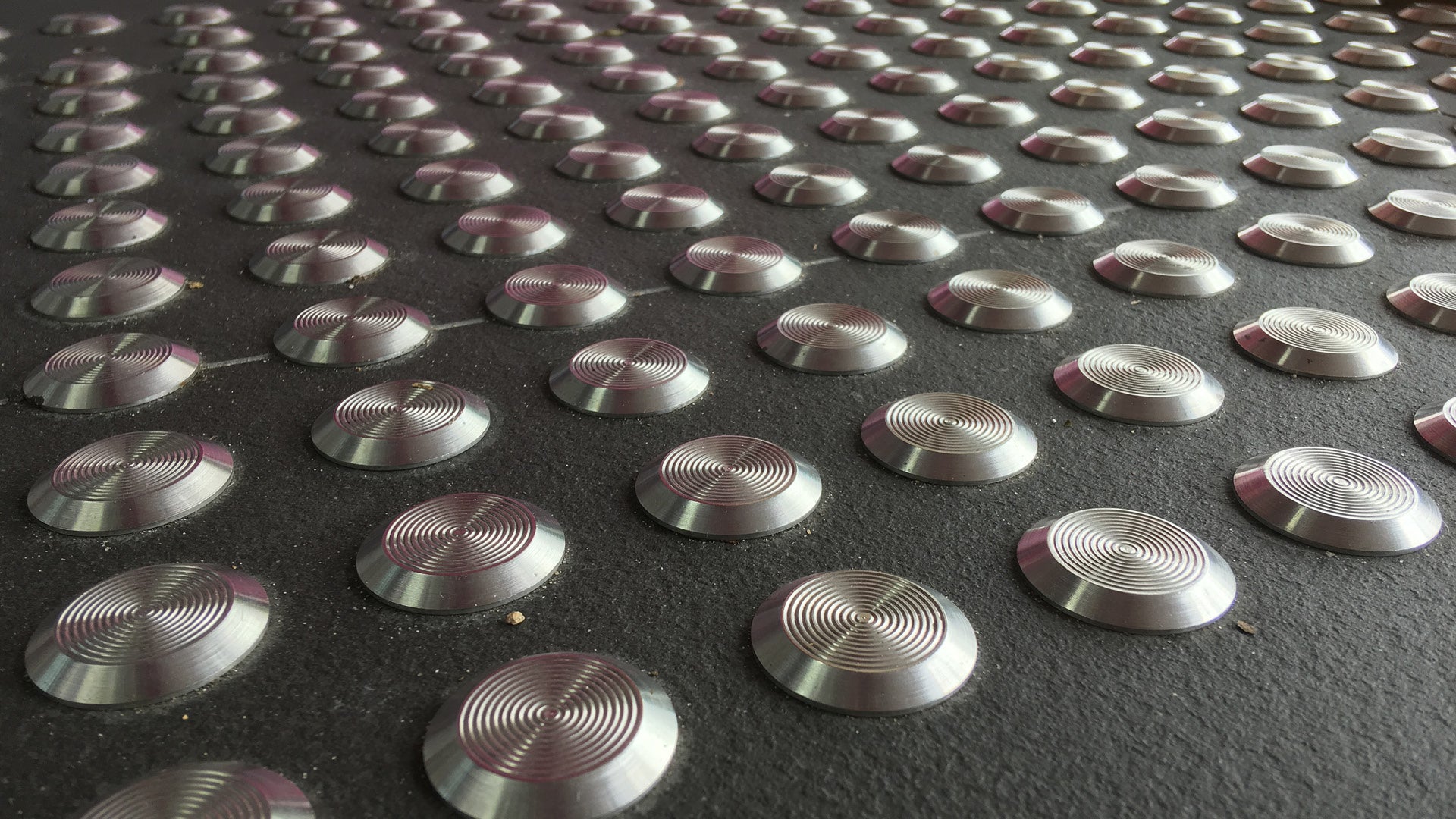
| Install method: drilled, inserted and glued OR screwed down screwed OR drilled and set in place
Application: new builds OR retro-fit
Preferred location: N/A (inside buildings only). | DO NOT use in open spaces due to reduced slip resistance when wet
NOT preferred, except where specified for a particular application. |
Fixing methods
Tactile fixing methods will vary depending on the following site characteristics:
- New build or retro-fit.
- Pedestrian only or pedestrian and vehicle traffic.
- High use or low use location.
- Precinct location.
- Tactile material selection.
- Substrate material.
See Table 3 and 4: TGSI materials (above).
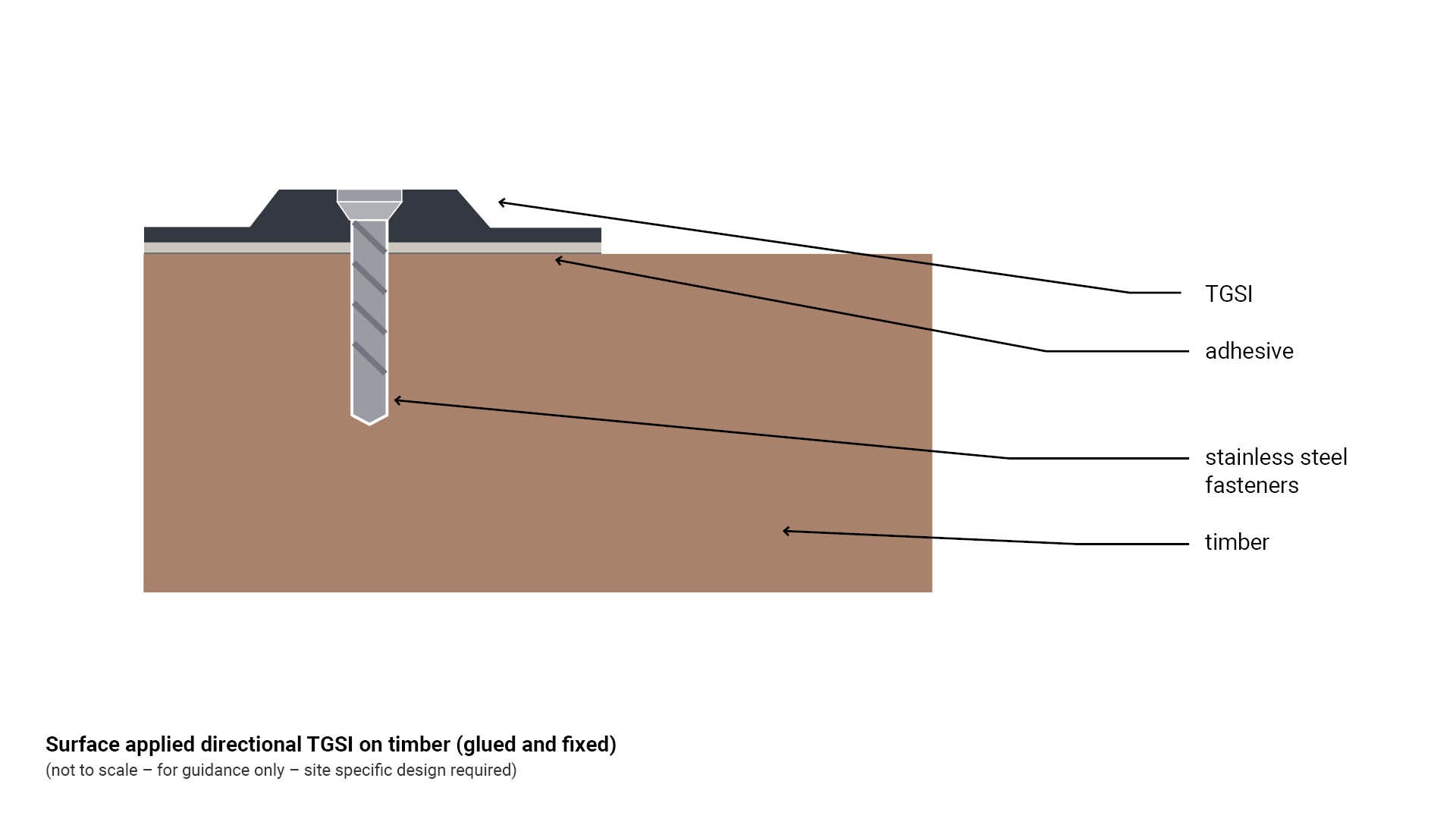
Surface applied fibre reinforced polymer (glued and fixed) TGSI
Warning and directional TGSI are mechanically and chemically fixed to a stable surface such as concrete, masonry, exposed aggregate, asphalt, timber, wood and wood plastic composite (WPC).
- Nylon anchors and tamper proof stainless steel fasteners provide a mechanical connection from the tactile to an existing surface.
- An adhesive such as Sikaflex 11FC (or equivalent) is applied to the base of the tactile to reduce lifting.
See Figure 11: Surface applied directional TGSI on timber (glued and fixed).
Figure 11: Surface applied directional TGSI on timber (glued and fixed)
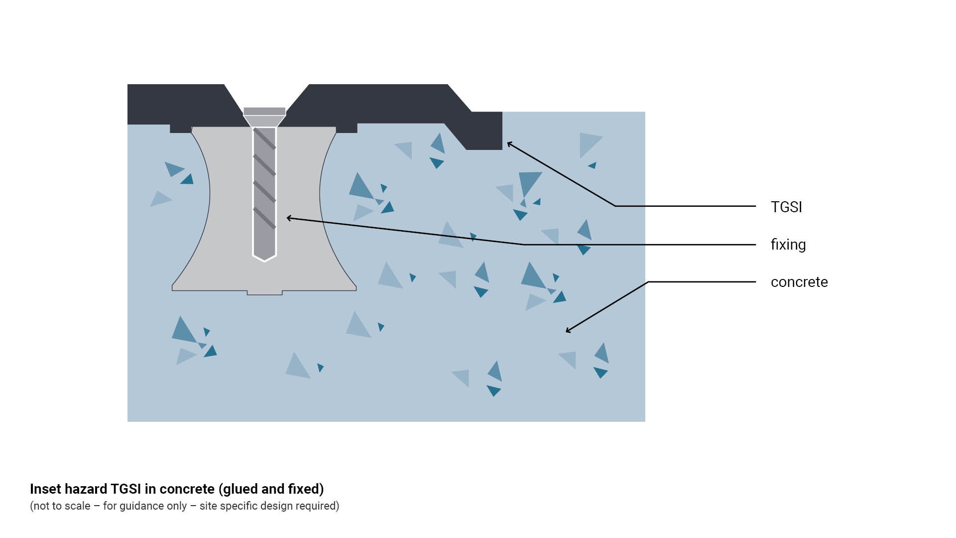
Inset fibre reinforced polymer (glued and fixed) TGSI
Warning and directional TGSI are applied during the wet curing of concrete. The result is a flush surface between the tactile and surrounding concrete.
- Once the concrete becomes cured, the TGSI is mechanically fixed to the finished surface or substrate.
- Nylon anchors and tamper proof counter sunk stainless steel fasteners provide a mechanical connection from the tile to the concrete.
- An adhesive such as Sikaflex 11FC (or equivalent) is applied to the base of the tile to reduce lifting.
- Replacement following damage may be difficult.
See Figure 12: Inset hazard TGSI in concrete (glued and fixed).
Figure 12: Inset hazard TGSI in concrete (glued and fixed)
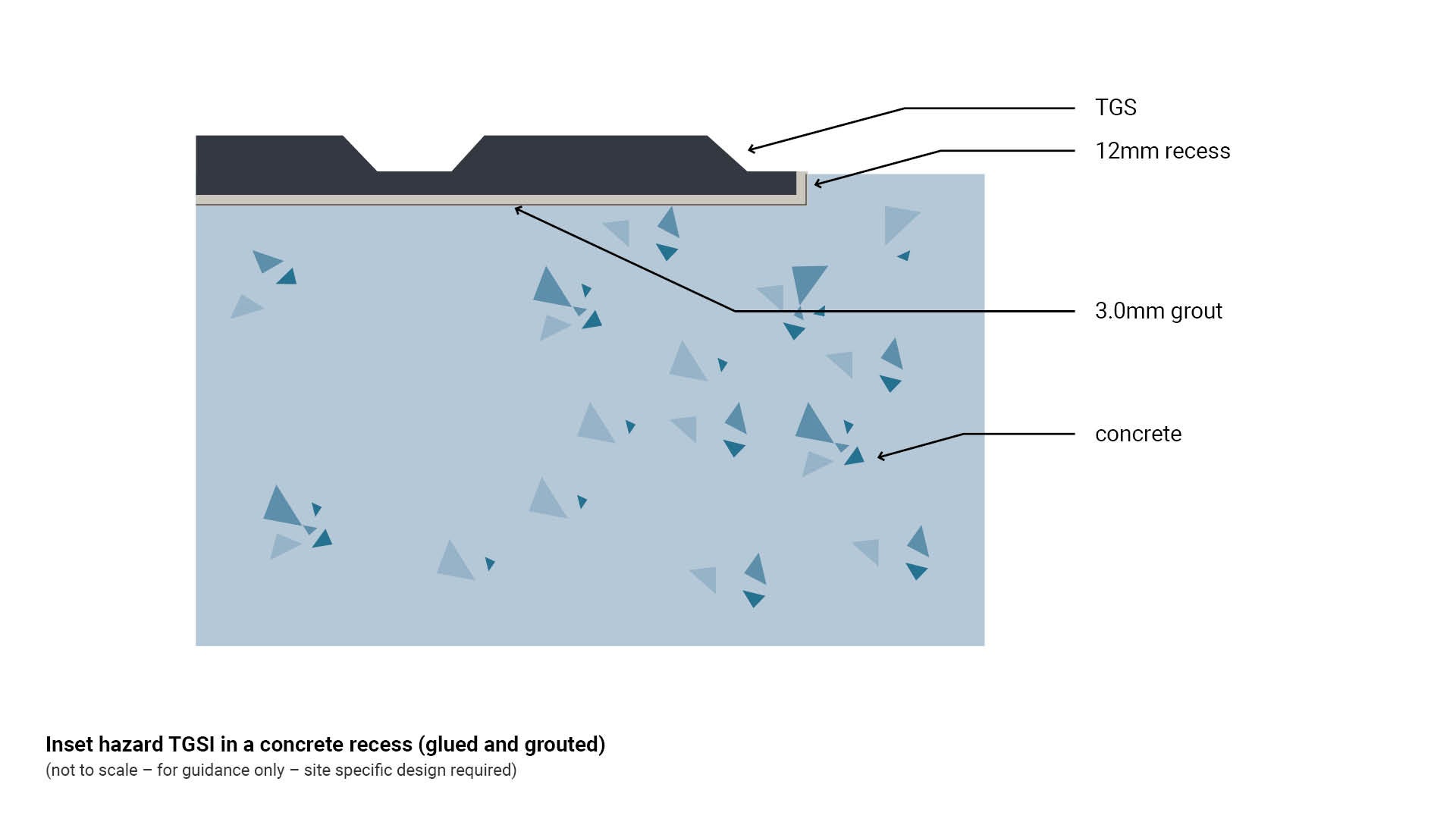
Inset porcelain (glued and grouted) TGSI
Warning and directional TGSI are laid into a recess formed into concrete, bitumen or pavers.
- Sufficient length and width is required to ensure a 3.0 mm grout allowance surrounding the tactile.
- A recess may be formed in wet concrete to accommodate the porcelain tactile.
- Tactile dimensions: 300 mm x 300 mmx 10 mm deep.
- Porcelain tactiles are laid using an approved adhesive, to form a flush surface between the tactile base and the surrounding substrate.
See Figure 13: Inset hazard TGSI into a concrete recess (glued and grouted).
Inset concrete TGSI
Warning and directional TGSI are laid into a recess formed into concrete, bitumen or pavers.
- Installed onto a sand/cement base with a grout allowance surrounding the tactile.
- Tactile dimensions: 300 mm x 300 mm x 40-60 deep.
See Figure 13: Inset hazard TGSI into a concrete recess (glued and grouted).
Figure 13: Inset hazard TGSI into a concrete recess (glued and grouted)
Luminance contrast
Luminance contrast is the difference in the amount of light reflected from the surface of a TGSI, compared to the amount of light reflected from a background surface.
Luminance factor is the ratio of luminance of a surface to that of a perfect reflector.
- Measure of luminance contrast may be undertaken using a ‘tristimulus colorimeter’ or ‘spectrophotometer’.
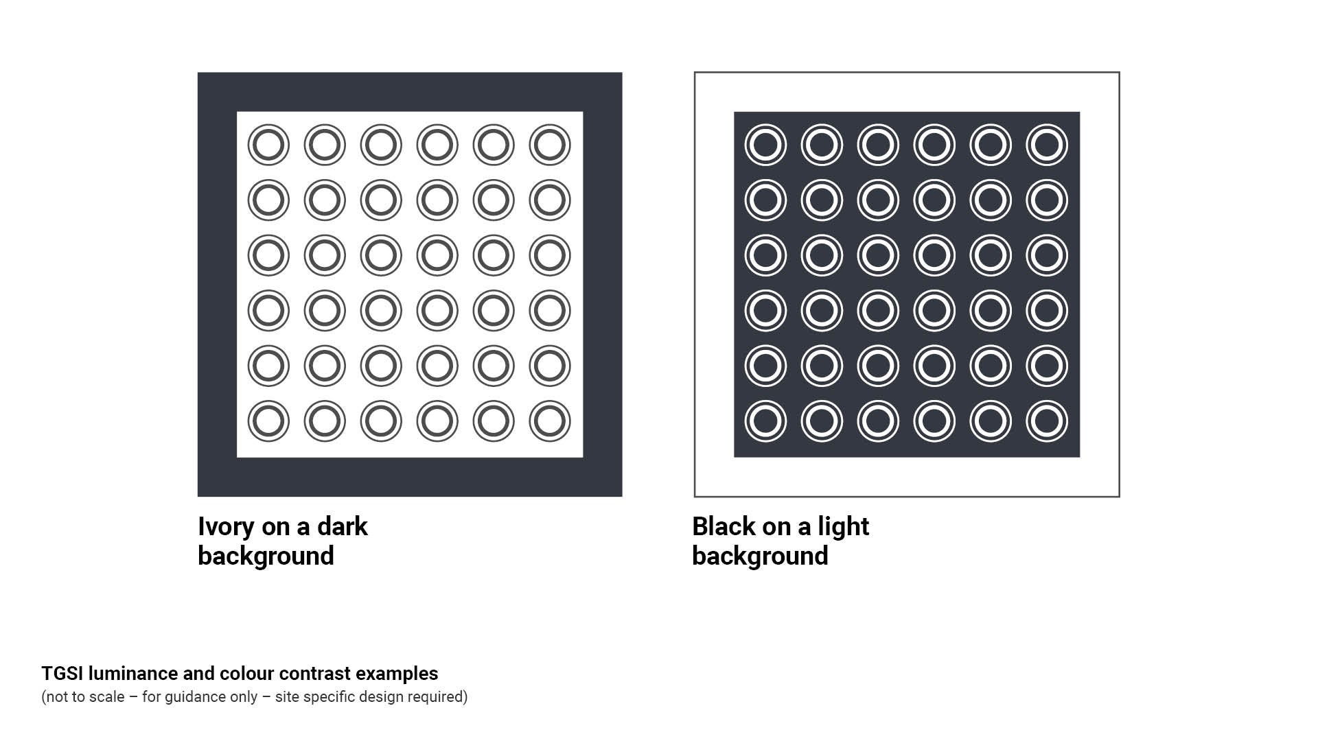
- TGSI are to be a suitable colour to achieve luminance contrast with the background against which they are to be viewed, with a luminance factor dependant upon the TGSI type selected. Site specific professional judgement and interpretation is required. As a general rule:
- select a dark coloured TGSI for installation to a light coloured background
- select a light coloured TGSI for installation to a dark coloured background.
- AS 1428.4.1:2009 – Design for access and mobility. Part 4: Means to assist the orientation of people with vision impairment – Tactile ground surface indicators Table E Values of luminous reflectance required to provide adequate luminance contrast as a function of surround luminous reflectance, sets out a method of using luminance reflectance values to calculate the required luminance contrast of a TGSI where the luminance reflectance’s of the TGSI and the background are known.
Colour contrast – general principles
TGSI are available in a range of colours:
- Ensure a difference in colour between the TGSI and the base surface to which they are installed. Consider that concrete pathways fade with age, to light grey. For example:
- avoid installing light grey TGSI on a light grey concrete path.
- avoid installing black TGSI on black asphalt.
- Colour blindness is an inability to see certain colours in the usual way.
- Colour blindness occurs in about 8% of males and about 0.4% of females.
- The most predominant form of colour blindness is the loss of reds and greens.
- Where deviating from preferred Council colour schemes, avoid ‘ripening tomato’ coloured TGSI on a terracotta coloured background. Both the TGSI and the background may appear grey to people who are colour blind.
- Consider that people with low sight can see yellow, white and blue longer than other colours.
See Figure 14: TGSI luminance and colour contrast examples.
Colour and luminance contrast
The TGSI colour and luminance contrast requires assessment based upon site specific conditions (such as full sun/part sun/full shade) and surrounding material such as asphalt or colour of the surrounding concrete.
- The designer must select a product whose colour considers site specific conditions such as background colour for retro-fit or new installations of TGSI.
- In order to provide a cohesive design, the start and end of the journey should be the same colour TGSI (only if luminance contrast can be achieved at all locations).
Figure 14: TGSI luminance and colour contrast examples
TGSI luminance contrast requirements under AS 1428.4.1
Tactile Ground Surface Indicators (TGSIs) must provide sufficient luminance contrast with the surrounding pavement surfaces to ensure they are clearly distinguishable to people with low vision, as required by AS 1428.4.1. This contrast enables users to reliably detect the presence, location, and extent of the tactile indicators, supporting safe and independent navigation in public spaces.
Consider the prevailing light conditions at the site. Determine if the site is predominately in full sun or full shade. Site specific investigation and professional judgement is required.
- If the site is primarily in full shade, select a TGSI colour which is highly visible in those conditions.
- If the site is primarily in full sun, select a colour which is highly visible in those conditions. Consider surface glare from surrounding infrastructure.
- Take sample TGSI colours to site to determine a suitable colour in the prevailing site conditions.
- Required luminance contrast is dependant upon TGSI type:
- integrated TGSI tiles or pavers (preferred)require a 30% luminance contrast with the background against which they are to be viewed
- discrete TGSI buttons (not preferred) individually installed, require a 45% luminance contrast with the background against which they are to be viewed
- composite TGSI buttons (not preferred) (made from two different colours), require a 60% luminance contrast for a diameter of 24 mm to 25 mm on the raised surface.
- TGSI manufacturer information may provide luminance factors for products.
- Substantiate the TGSI installation is compliant:
- For works covered by the National Construction Code (NCC) all certificates of classification must be supported by a Form 16 (confirms the luminance contrast has been achieved).
- For all other works, a test report from a NATA accredited testing laboratory which confirms either a laboratory test of all surfaces or an in-situ test has been satisfactorily completed. Test results to be attached to the design drawings.
- Test criteria must be in accordance with AS 1428.4.1:2009 Design for access and mobility.
Factors affecting TGSI colour selection
Council Precinct
- If TGSI’s are located within a ‘precinct’ the colour and type shall be determined in the first instance by the Sunshine Coast Centres Design Palette, except where luminance contrast cannot be achieved, then consult with the relevant Council department. Where a precinct colour is undetermined the following is to apply:
- TGSI’s are to be ‘black’ in the first instance (only where luminance contrast can be achieved).
- Where ‘black’ does not achieve luminance contrast, then TGSI’s are to be ‘white’ (only where luminance contrast can be achieved).
- If neither ‘black’ nor ‘white’ are compliant, then any deviation the above must be to the approval of the relevant SCC department.
SCC Open space areas (other than precincts)
- TGSI’s are to be ‘black’ in the first instance (only where luminance contrast can be achieved).
- Where ‘black’ does not achieve luminance contrast, then TGSI’s are to be ‘white’ (only where luminance contrast can be achieved).
- If neither ‘black’ nor ‘white’ are compliant, then any deviation from this standard must be to the approval of Cuoncil (Parks and Gardens).
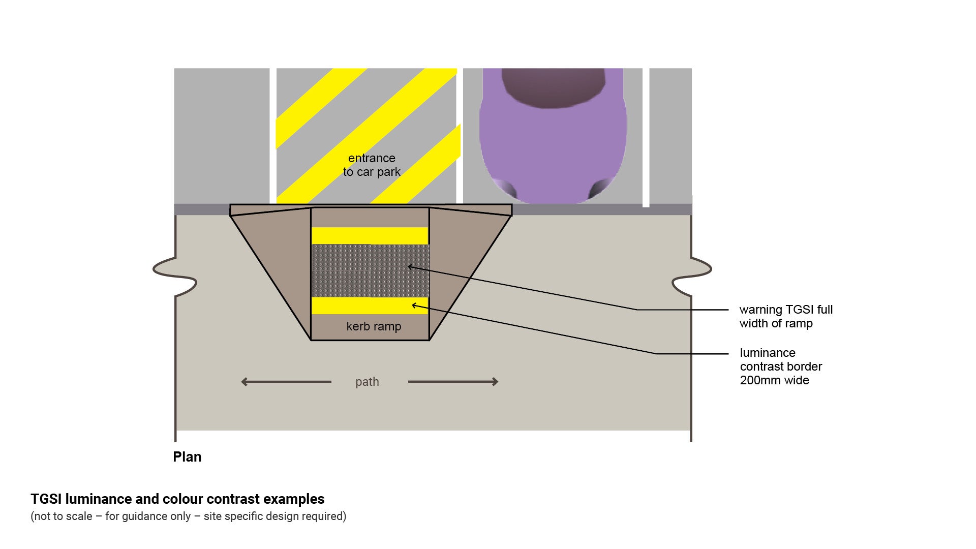
Retrofit to increase luminance contrast
A temporary retrofit option can be installed to increase luminance contrast on the non-compliant kerb ramp.
To be used where replacement of the whole ramp is not an immediate option:
- Consider using a luminance contrasting painted border with a minimum width of 200 mm into the adjacent pedestrian surface to improve luminance contrast between the TGSI’s and the adjacent surface as a temporary solution.
- This retrofit solution is advice from an accredited access consultant and should only be used as a temporary measure to enhance luminance contrast prior to complete replacement of the ramp.
- This is a temporary solution only and is not be used as a substitute for full replacement of a ramp.
- The preferred treatment is full replacement of a non-compliant kerb ramp.
See Figure 15: Example – to enhance luminance contrast.
Figure 15: Example – to enhance luminance contrast
Slip resistance

Slip resistance is the science of measuring the resistance of flooring surfaces to slip incidents.
Product information brochures may quote slip resistance values.
The ramp test involves an individual standing on a ramp at various angles of incline either:
- Method 1 – barefoot on a water lubricated ramp or
- Method 2 – in rubber soled boots on an oil lubricated ramp.
Slip testing classification by the ramp method is expressed as ‘R’ rating:
- R9 Person slips at a 6° to 10° angle of elevation
- R10 Person slips at a 10° to 19° angle of elevation
- R11 Person slips at a 19° to 27° angle of elevation
- R12 Person slips at a 27° to 35° angle of elevation
- R13 Upwards of 35° angle.
Slip testing classification (pendulum or ramp) number may be preceded by:
- ‘V’ – external ramps
- ‘W’ – external colonnade, walkway and pedestrian crossing
- ‘W’ – swimming pool surrounds and communal shower rooms
- ‘X’ – entry foyers office and public buildings – wet
- ‘X’ – communal changing rooms
- ‘X’ – internal ramp slopes greater than ˃2° – dry
- ‘Z’ – entry foyers office and public buildings – dry.
The wet pendulum test uses a pendulum friction tester (tribometer) to measure the frictional force offered by simulating a foot moving over a water-contaminated surface. Generally undertaken in a laboratory and used for new pedestrian surface materials.
The tribometer instrument reading is expressed as a British Pendulum Number (BPN), a dimensionless unit of slip resistance.
Slip testing classification by the wet pendulum test method is expressed as ‘BPN’:
- Class V – Mean BPN ˃45, Slip resistance ˃0.59
- Class W – Mean BPN 45 - 54, Slip resistance ˃0.47-0.59
- Class X – Mean BPN 35 - 44, Slip resistance ˃0.36-0.46
- Class Y – Mean BPN 25 - 34, Slip resistance ˃0.25-0.34
- Class Z – Mean BPN ˂25, Slip resistance ˂0.25.
Efflorescence in TGSI
The process of efflorescence on TGSI tiles is caused by multiple factors which result in surface deposits that dull the appearance of the tactile.
- With a reduction in the appearance of the tactile colour, luminance contrast may also be reduced.
- Sealing products may be used on some materials however they require ongoing re-application and are not tested over time.
Alternative options
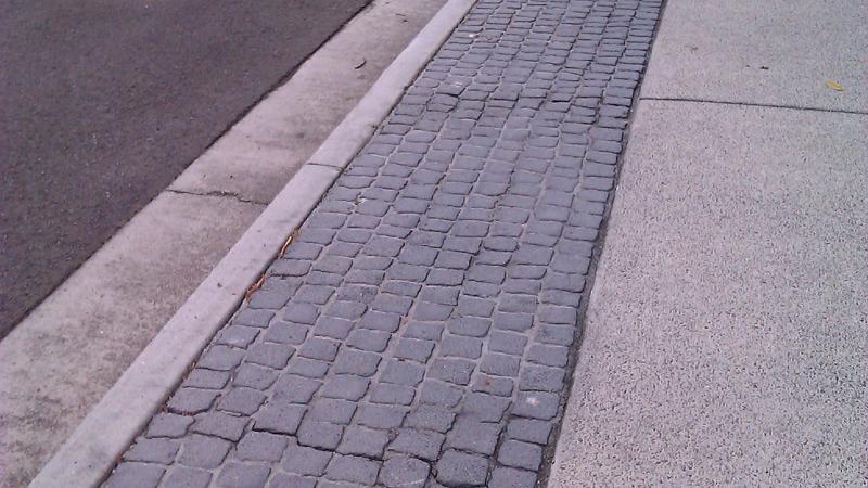
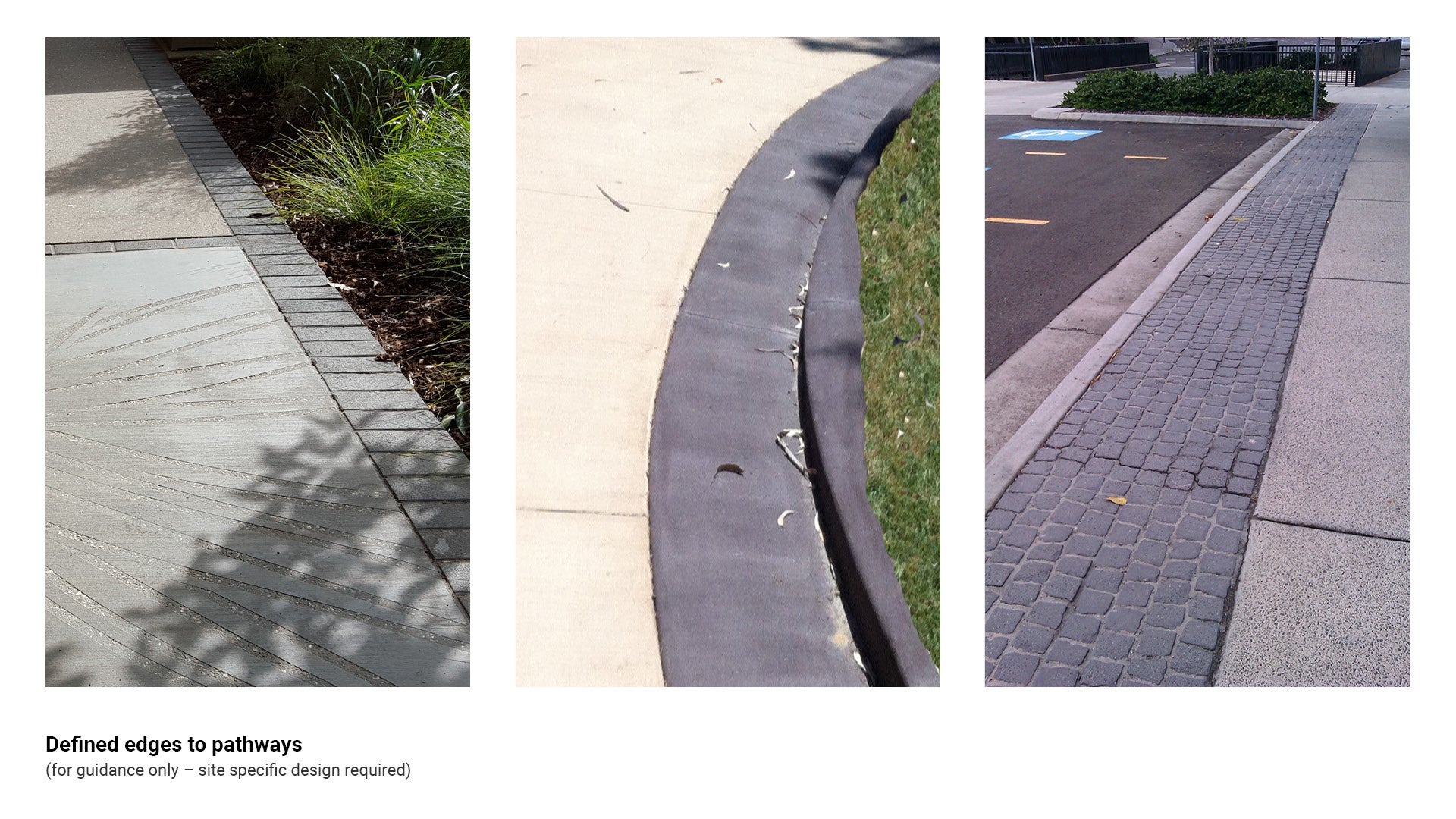
Defined pathway edges
Tactile ground surface indicators (TGSI) are an essential tool to assist people who are blind or vision impaired to navigate public places safely, with dignity and confidence.
- Ensure TGSI installations are not over-used.
- Minimise the use of TGSI where possible as inappropriate use or over-use use can create confusion.
- It is important that TGSI are not installed where sufficient tactile cues already exist such as at:
- defined edges to pathways; either raised edges or luminance contrasting edges with legible surfaces
- raised planting areas which provide direction within large pedestrian spaces
- walls, fences, railing systems, tapping rails.
- These cues can be used for way-finding information by people who are blind or vision impaired.
- Consult an access consultant accredited by Association of Consultants in Access Australia Inc. (ACAA) for site specific advice.
See Figure 16: Defined edges to pathways.
Figure 16: Defined edges to pathways
This component is currently in development