Irrigation
Components
Suite of components for irrigation systems
All irrigation components must comply with the following:
- Be of an appropriate quality and pressure rating for the system in which they are used.
- Conform to the relevant standards.
- Where required, all tests are to be carried out and certified.
Irrigation components include:
- System controller components (irrigation control system)
- Back flow prevention devices
- Pipework
- Valves
- Valve boxes
- Emitters
- Fittings
- Wire and cable.
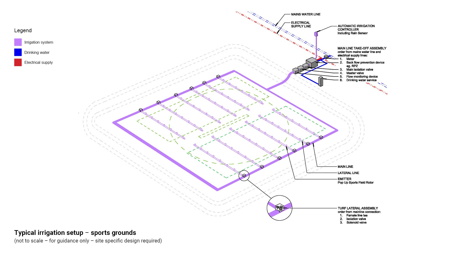
See the following figures for typical irrigation setups:
- Figure 2: Typical irrigation setup – parks and gardens.
- Figure 3: Typical irrigation setup – sports grounds.
Figure 2: Typical irrigation setup – parks and gardens
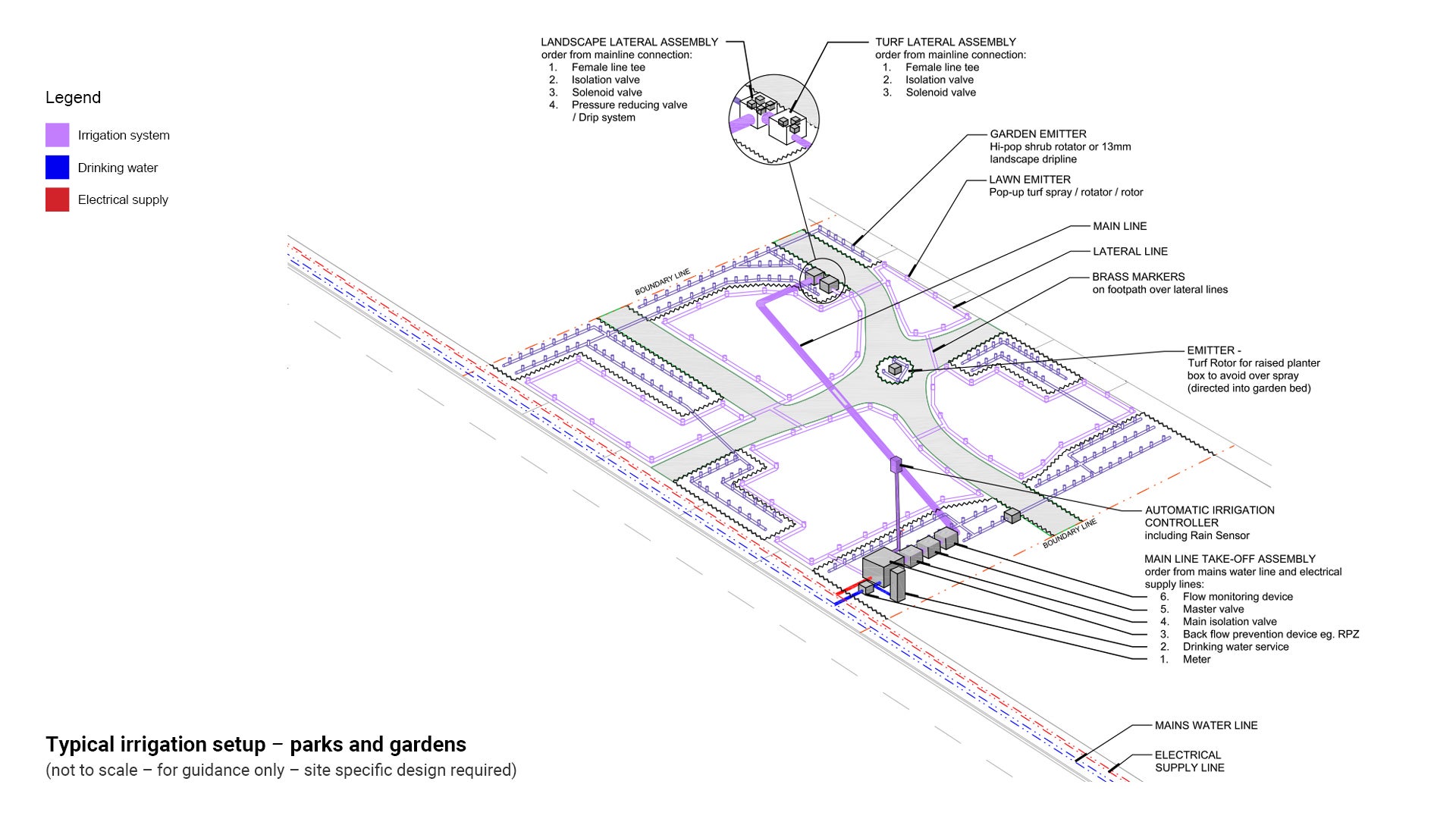
Figure 3: Typical irrigation setup – sports grounds
System controller components (irrigation control system)
Irrigation control system components should include the following attributes:
- Waterproof housing
- Battery backup.
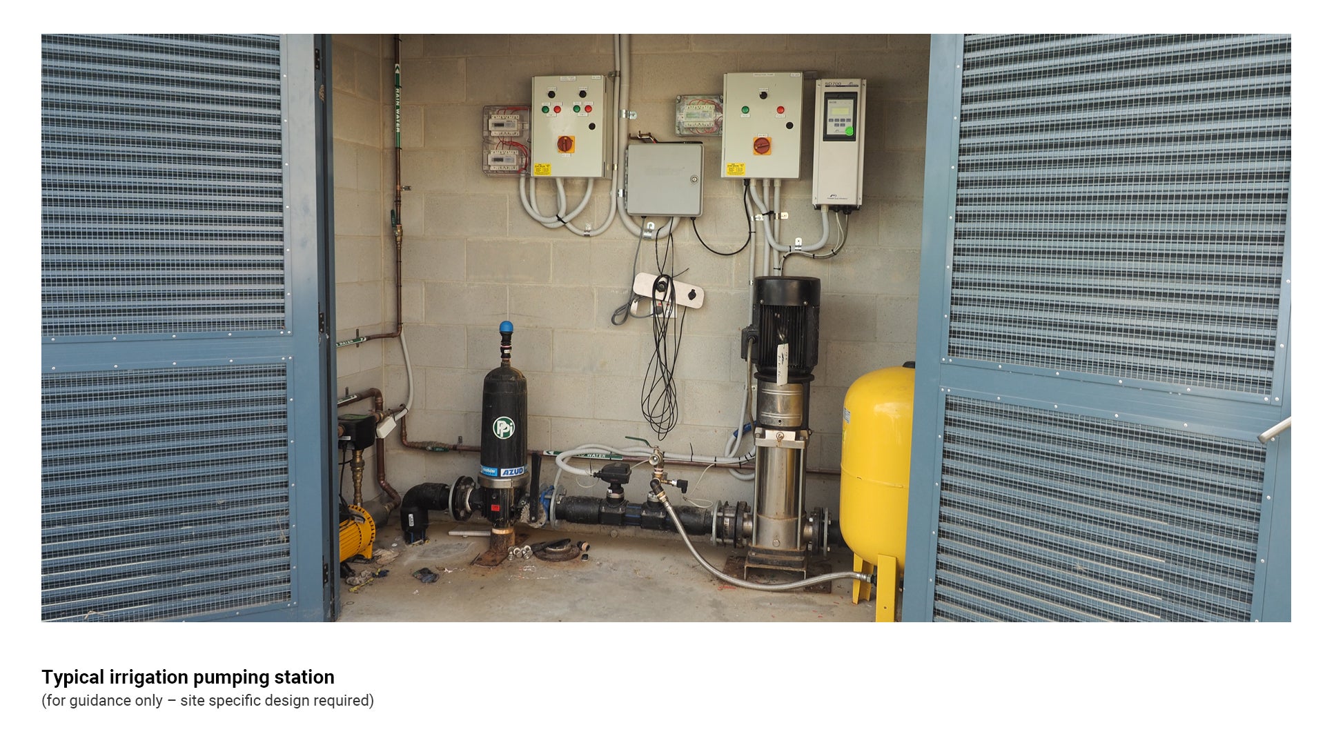
Irrigation pumping station
The irrigation pumping station houses all the electrical and irrigation controllers in a secure cabinet or room. Considerations are to be made for the following:
- Pump station is to be secure and padlockable
- Weatherproof
- Size is to be dependent on the size and number of pumps and pipework.
See the following for further guidance:
- Figure 4: Typical irrigation pumping station
- Table 1: System controller components types.
Figure 4: Typical irrigation pumping station
Automatic irrigation controllers/variable speed drive
An automatic irrigation controller is a hydraulic or electronic device used to operate irrigation systems such as turf sprinklers and drip irrigation. They are used to provide automated, unattended operation of irrigation equipment.
Must be compatible with Smart Irrigation Control System. Consider system design and required number of stations when selecting compatible irrigation controller.
- Automatic irrigation controllers have the capacity to program numerous settings, such as:
- Frequency
- Duration
- Volume
- Start and finish times.
- Some controller types have additional features such as:
- Multiple programs to allow different watering frequencies for differing plant types
- Rain delay settings/rain sensor override.
- Individual station run times.
- Battery backup.
- Input terminals for sensors including:
- Rain sensors
- Freeze sensors
- Soil moisture sensors
- Weather data
- Remote operation.
- Irrigation controllers shall be installed inside a building or within a lockable cabinet to prevent damage due to weather or vandalism, and to prevent unapproved program changes. The following features should be considered for irrigation controller cabinets:
- Lockable door, utilising a Parks 30 key and locking system
- Weatherproof
- Stainless steel
- Wall mounted.
- Controllers shall be installed adjacent to:
- Irrigation pumps
- Dedicated double 240-volt GPOs.
See the following for further guidance:
- Figure 5: Typical Automatic irrigation controllers/Variable speed drive
- Table 1: System controller components types.
Figure 5: Typical Automatic irrigation controllers/Variable speed drive
Smart technology
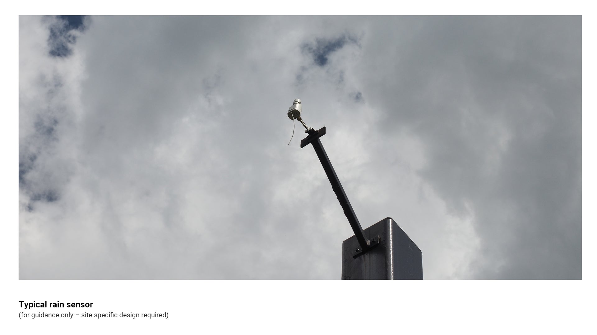
Rain sensors
- A rain sensor is an automated device that detects rainfall and can shut off the irrigation system, or prevent the system from commencing during rain events.
- Rain sensors are adjustable to allow for differing moisture levels. These adjustments are to be site specific, and determined by the differing site conditions, e.g. soil type, location.
- Sensors are to be placed in a position so that rainwater can be collected without external obstruction.
- Rain sensors are available in models that are wireless or hard-wired into the irrigation controller.
See the following:
- Figure 6: Typical rain sensor
- Table 1: System controller components types
- LIM Smart technologies for further guidance, including key considerations for installation.
Figure 6: Typical rain sensor
Flow meter
- A flow meter measures flow through the irrigation mainline when an irrigation zone is active.
- Using a flow meter allows irrigation managers to understand the quantity of water being used, and how much water is required through an irrigation system or zone. This information can be used to set parameters and alerts so irrigation managers can know when a system is having performance issues such as leaks or failed components.
- Flow meters are to be installed between the master valve and zone valves.
- Downstream of the flow meter, no taps are to be installed, as this can result in false alerts from the meter.
- In situations where all solenoids that are connected to the controller are not grouped together, more than one flow controller may need to be installed.
- Flow meters are to incorporate a pulse meter.
- Flow meters should be installed between straight sections of pipe (with no fittings) of the following lengths:
- Before meter - 10 times the pipe diameter
- After meter - 5 times the pipe diameter
- Flow meters should be pattern approved.
See the following:
- Figure 7: Typical flow meter
- Table 1: System controller components types
- LIM Smart technologies for further guidance, including key considerations for installation.
Figure 7: Typical flow meter
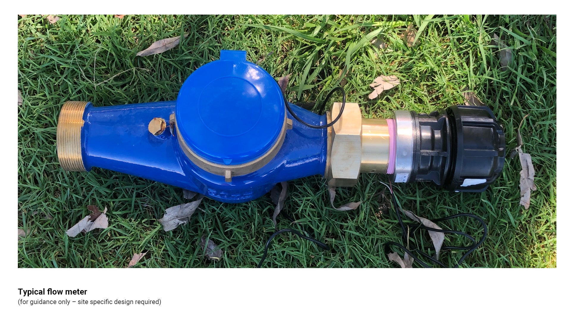
Table 1: System controller component types
Irrigation type | Recommended use/application | Key consideration |
Irrigation pumping station 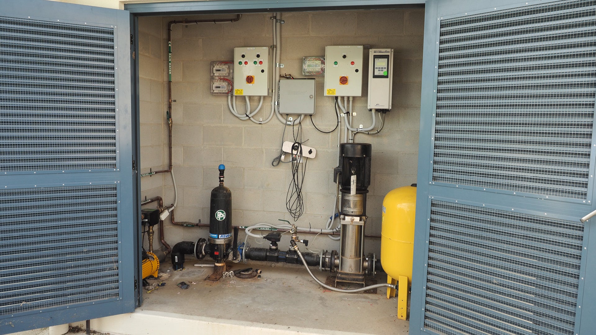 | Used to supply water to irrigation systems requiring high pressure. |
|
Irrigation controller box 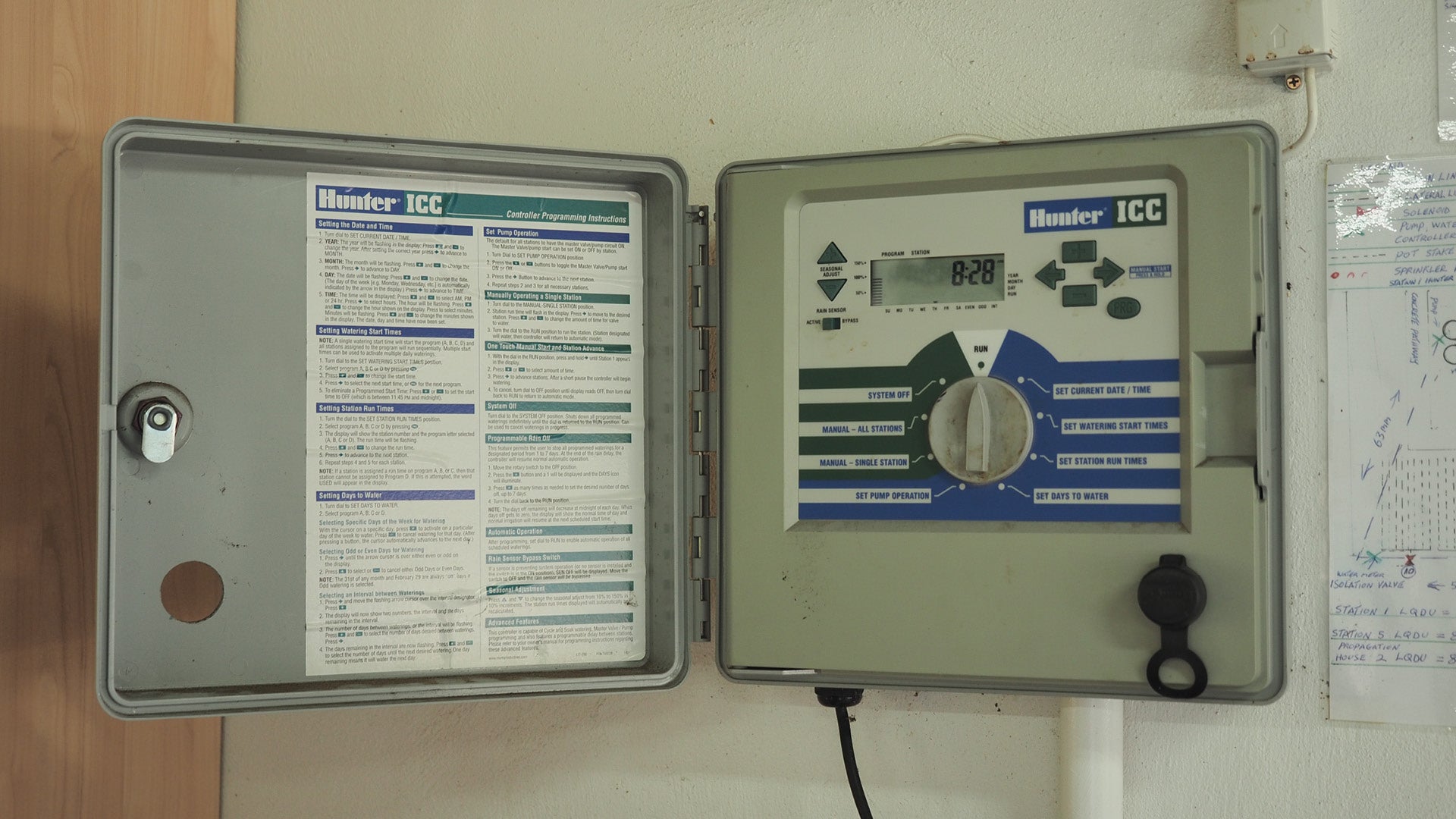 | Used to control and program automatic irrigation via electric solenoid valves. |
|
Variable speed drive 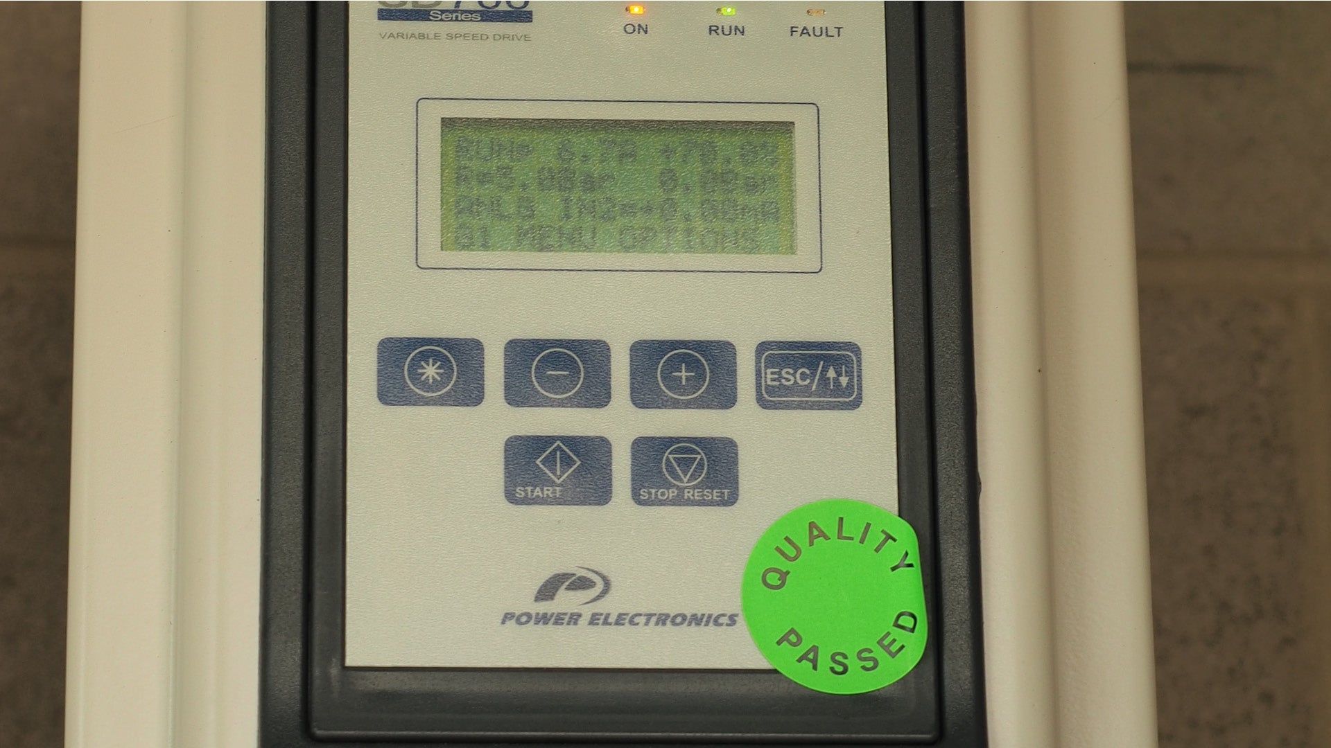 | Allows for a high level of water and power efficiency when connected to an irrigation pumping station. |
|
Warning sign - irrigation controls 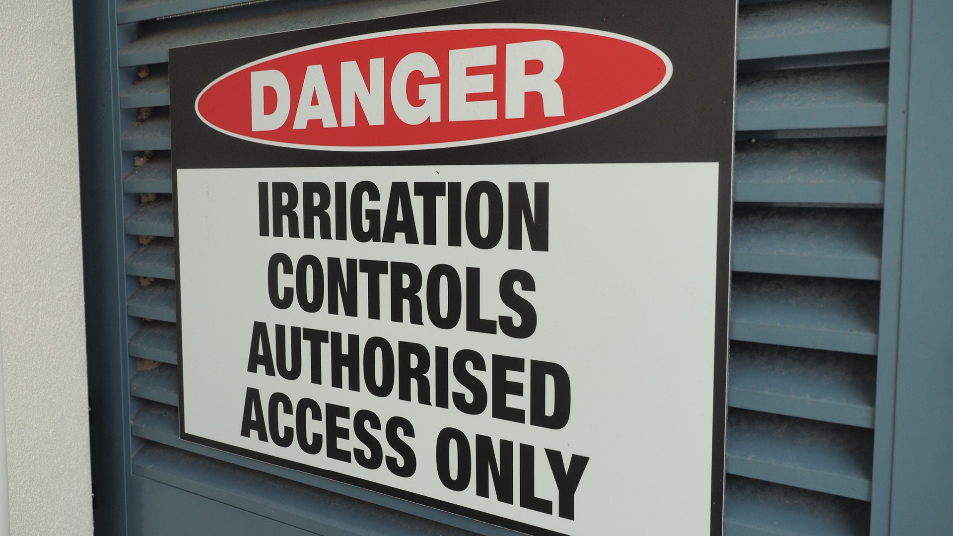 | Indicates presence of irrigation controls, and aims to prevent unauthorised access. | Clearly installed for public safety. |
Rain sensor 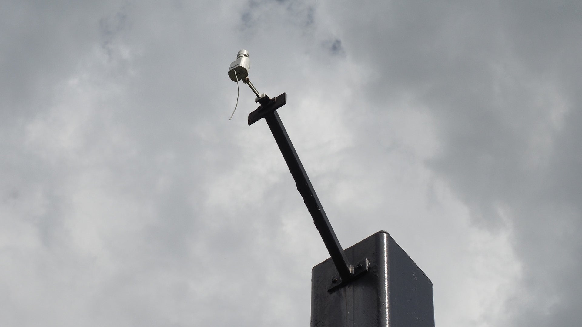 | Used in conjunction with an irrigation controller, a rain sensor shuts off irrigation when rain occurs. | Different models are able to be hard-wired directly into a controller, or available wirelessly. |
Water meter 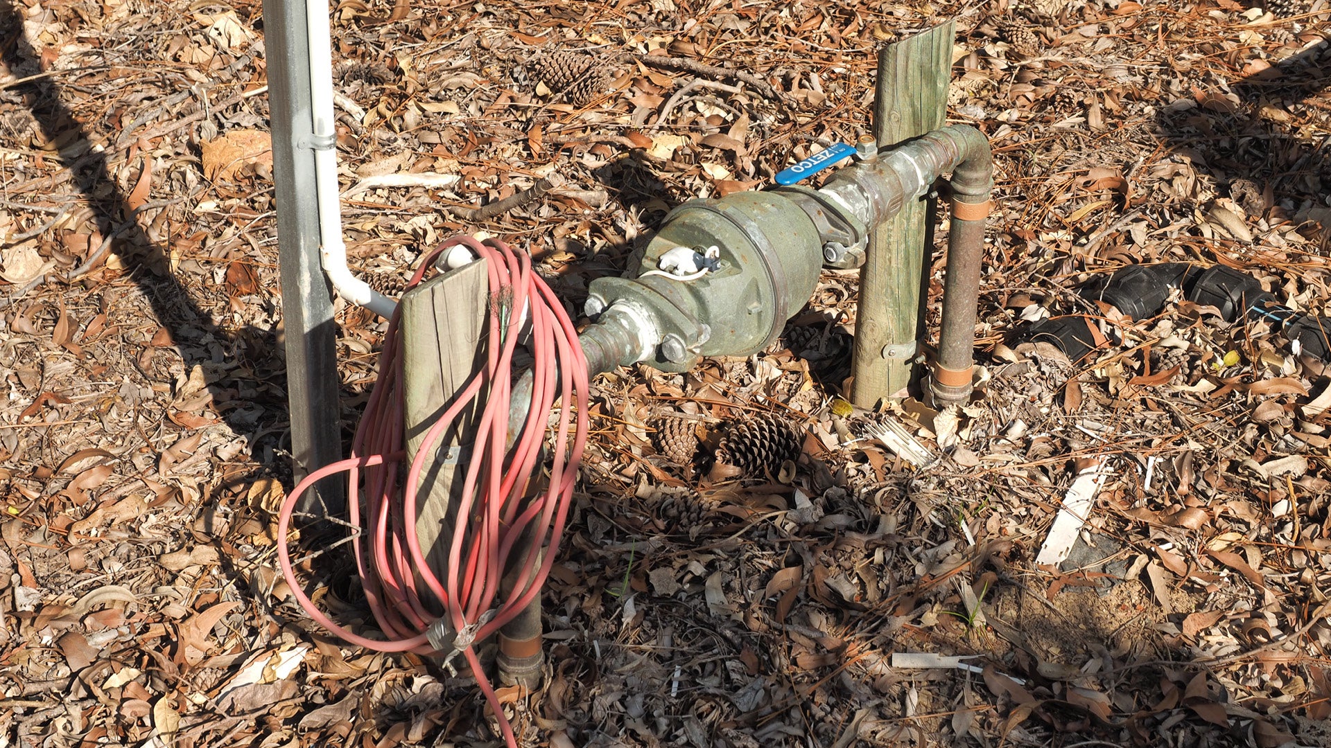 | Used to record water usage also used to determine cost to user. | Must be installed by a licensed plumber. |
Flow meter (flow monitoring device on sensor) 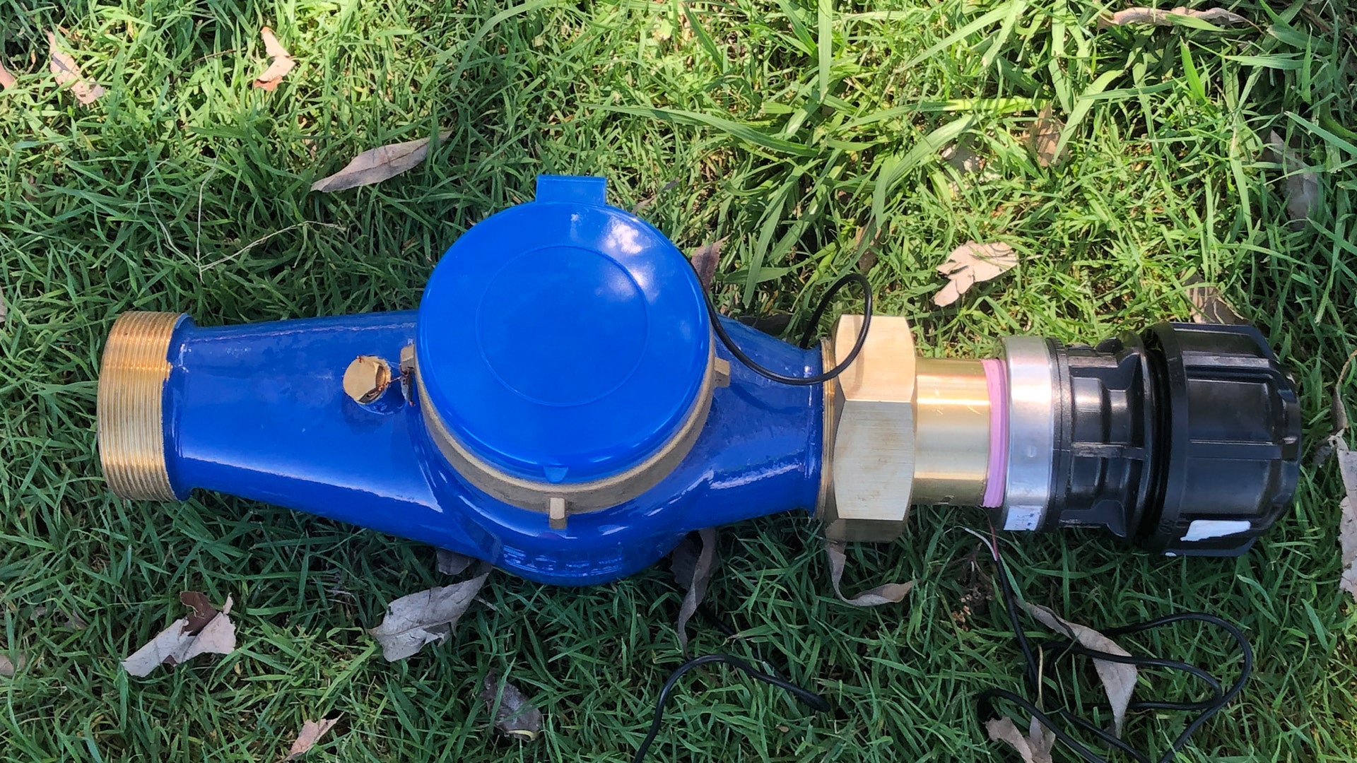 | Utilised to monitor designated flow through the irrigation system. |
|
Back flow prevention devices
Back flow prevention devices are spring loaded devices allowing water to travel in one direction only, automatically preventing reverse flow (backflow) which can potentially contaminate the mains supply.
Backflow prevention devices can be divided into the following categories:
- Low hazard contamination risk – Dual check valves (non-testable).
- Medium hazard contamination risk – Double check valve (testable).
- High hazard contamination risk – RPZ (testable).
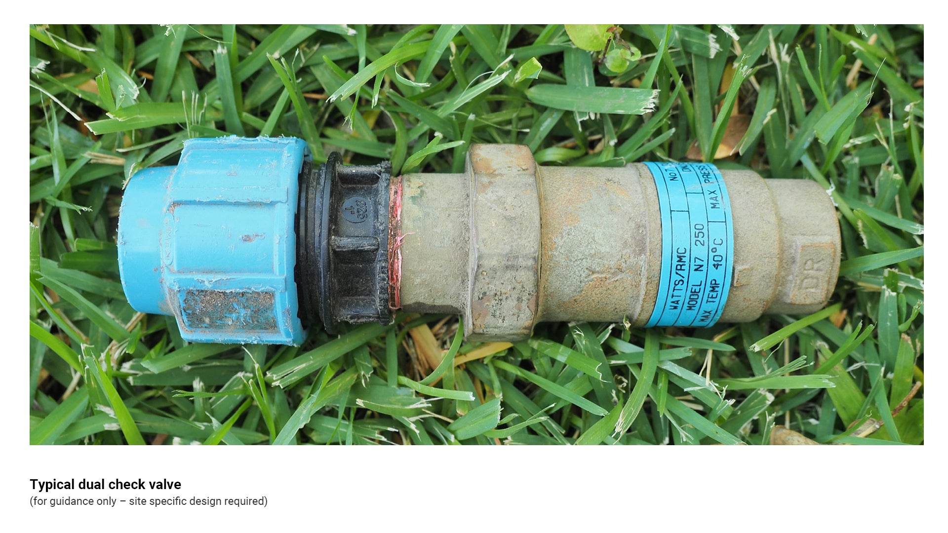
Dual check valves
Dual check valves are used where the risk of contamination to the mains supply is low, for example drinking fountains, taps, etc.
These valves are non-testable.
See the following for further guidance:
- Figure 8: Typical dual check valve
- Table 2: Back flow prevention devices.
Figure 8: Typical dual check valve
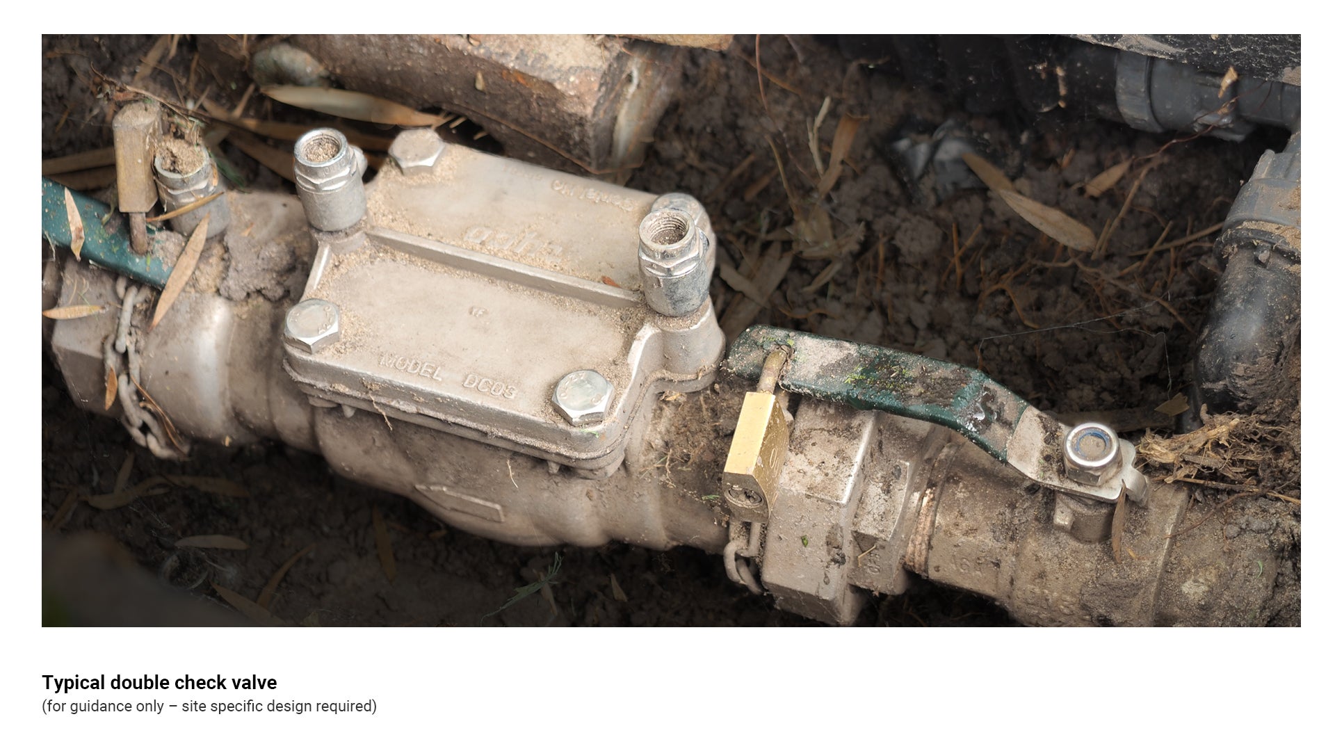
Double check valves
Double check valves allow flow in one direction only, automatically preventing backflow when fluid in the line changes direction.
These valves are testable, and are generally used in installations where a ‘medium hazard’ of contamination to the mains water supply exists.
Double check valves require a 100 mm clearance under the valve, and must be accessible for testing.
See the following for further guidance:
- Figure 9: Typical double check valve.
- Table 2: Back flow prevention devices.
Figure 9: Typical double check valve
Reduced pressure zone device (RPZ)
A reduced pressure zone device (RPZD, RPZ or RPZ valve) is the most secure and reliable of all backflow prevention devices.
- An RPZ must be installed above ground and have 300 mm clearance under the valve, and must be accessible for testing
- An RPZ is considered suitable for ‘high hazard’ situations for the following reasons:
- They prevent both back pressure and back siphonage.
- They are testable to verify correct operation.
- Due to redundant design (duplication of critical components), even with two check valves not operating correctly, the device still provides protection.
See the following for further guidance:
- Figure 10: Typical reduced pressure zone device (RPZ)
- Table 2: Back flow prevention devices.
Figure 10: Typical reduced pressure zone device (RPZ)
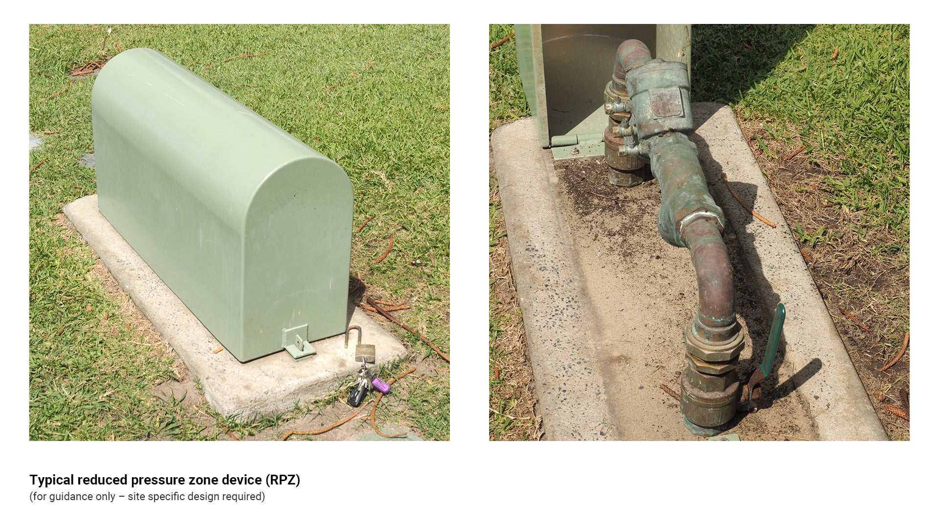
Table 2: Back flow prevention devices
Irrigation type | Recommended use/application | Key consideration |
Double check valve 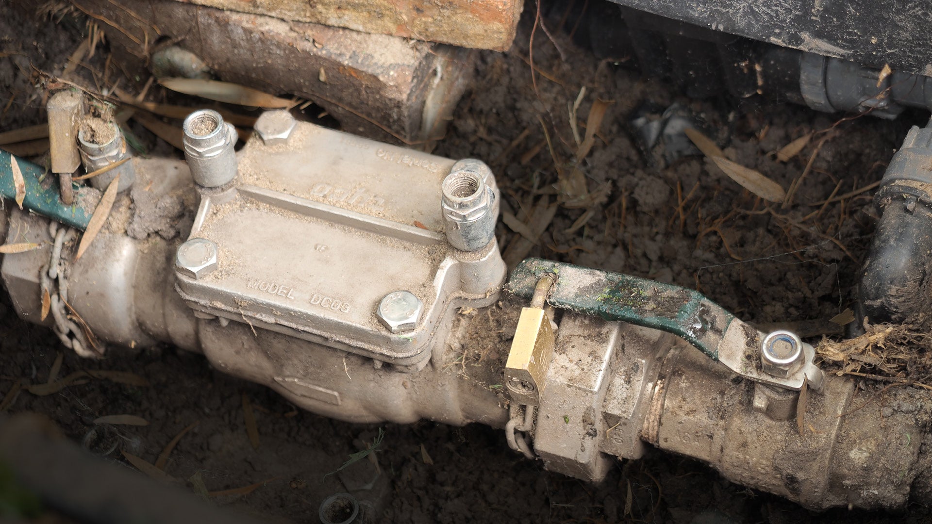 |
| Not suitable for high hazard situations. |
RPZ and enclosure 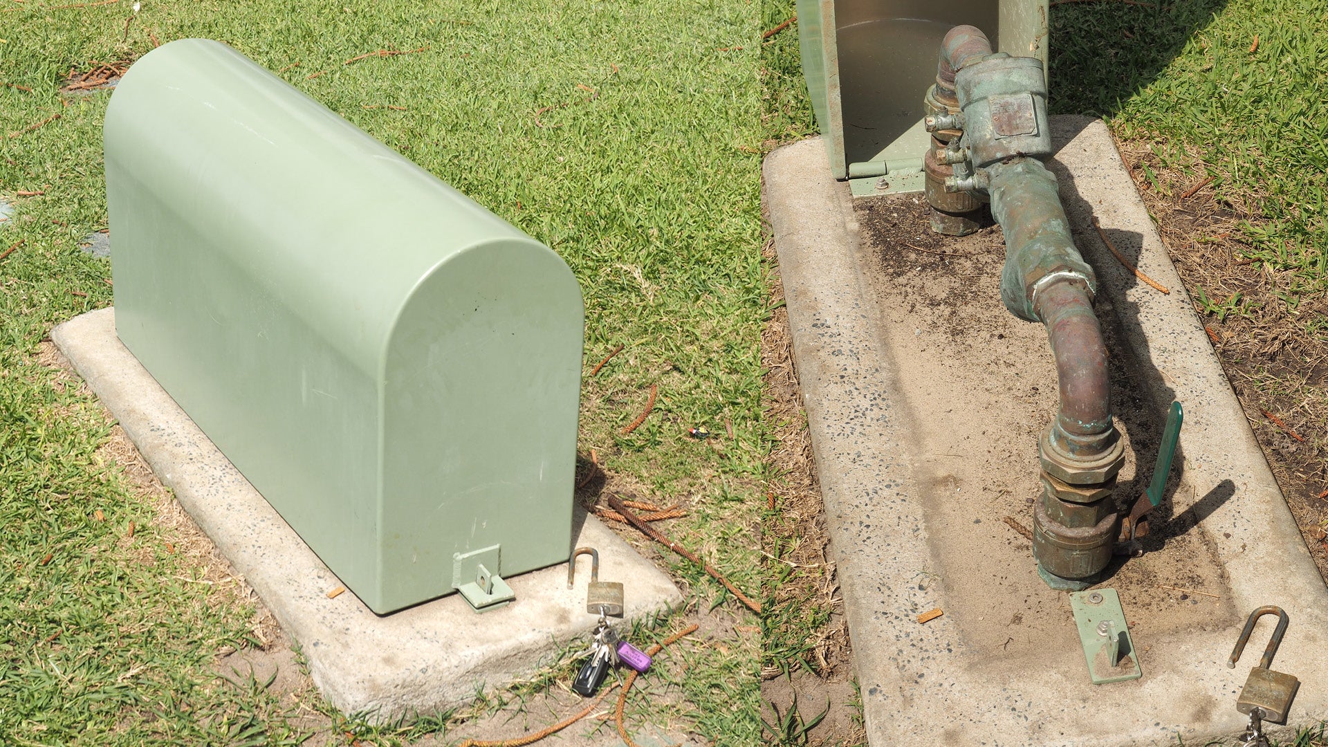 | Backflow prevention device to protect mains supply from contamination by harmful liquids or products. |
|
Dual check valve 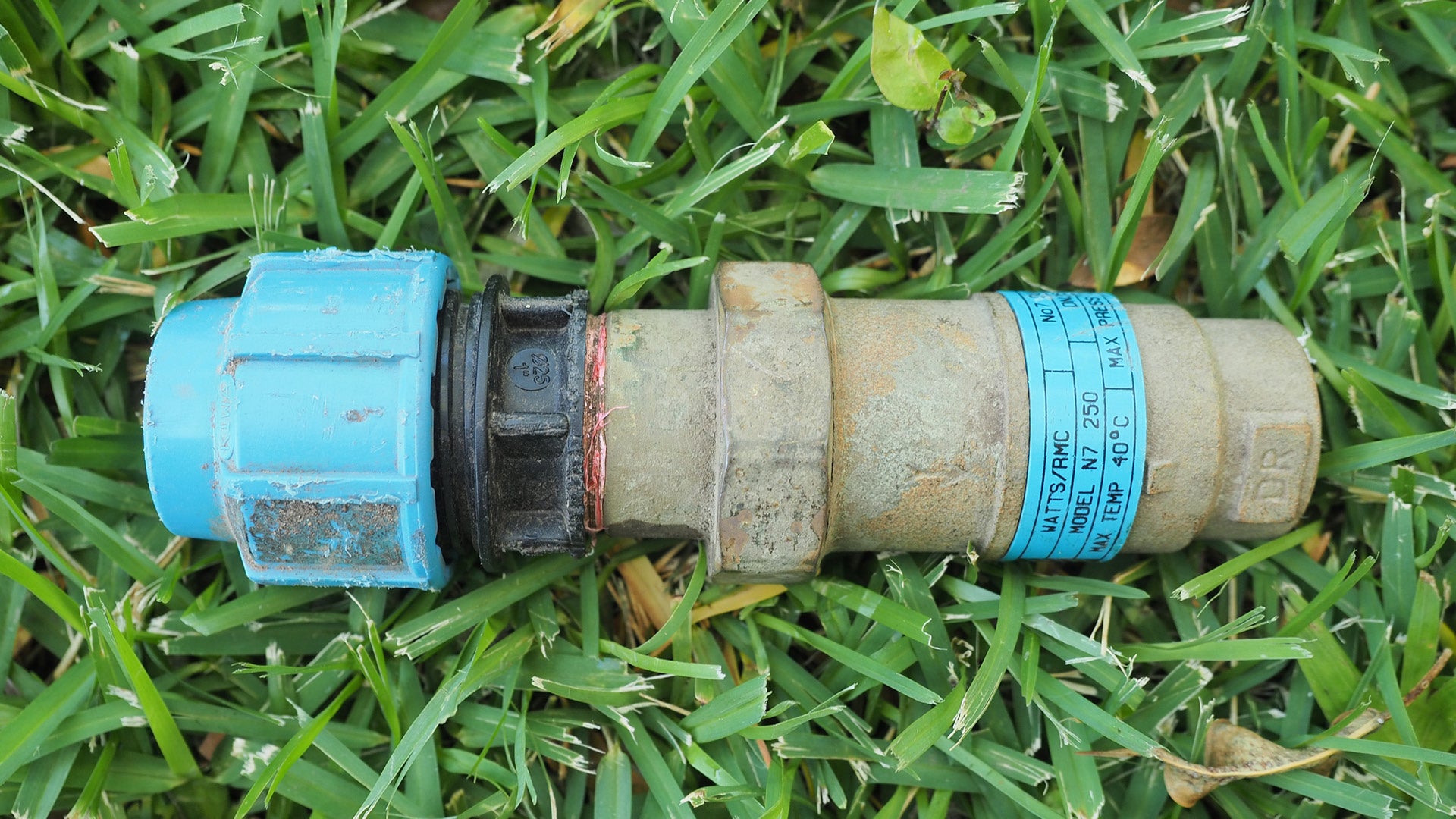 |
| Non-testable device. |
Pipework
Pipes for use in irrigation systems can be high density, medium density or low density polyethylene (HDPE, MDPE or LDPE), dependent on site conditions and design requirements.
Polyethylene is a resilient, sturdy material with good UV, corrosion, chemical and crack resistance. It is a long lasting pipe, ideal for moving water at high or low pressures in above or below ground applications.
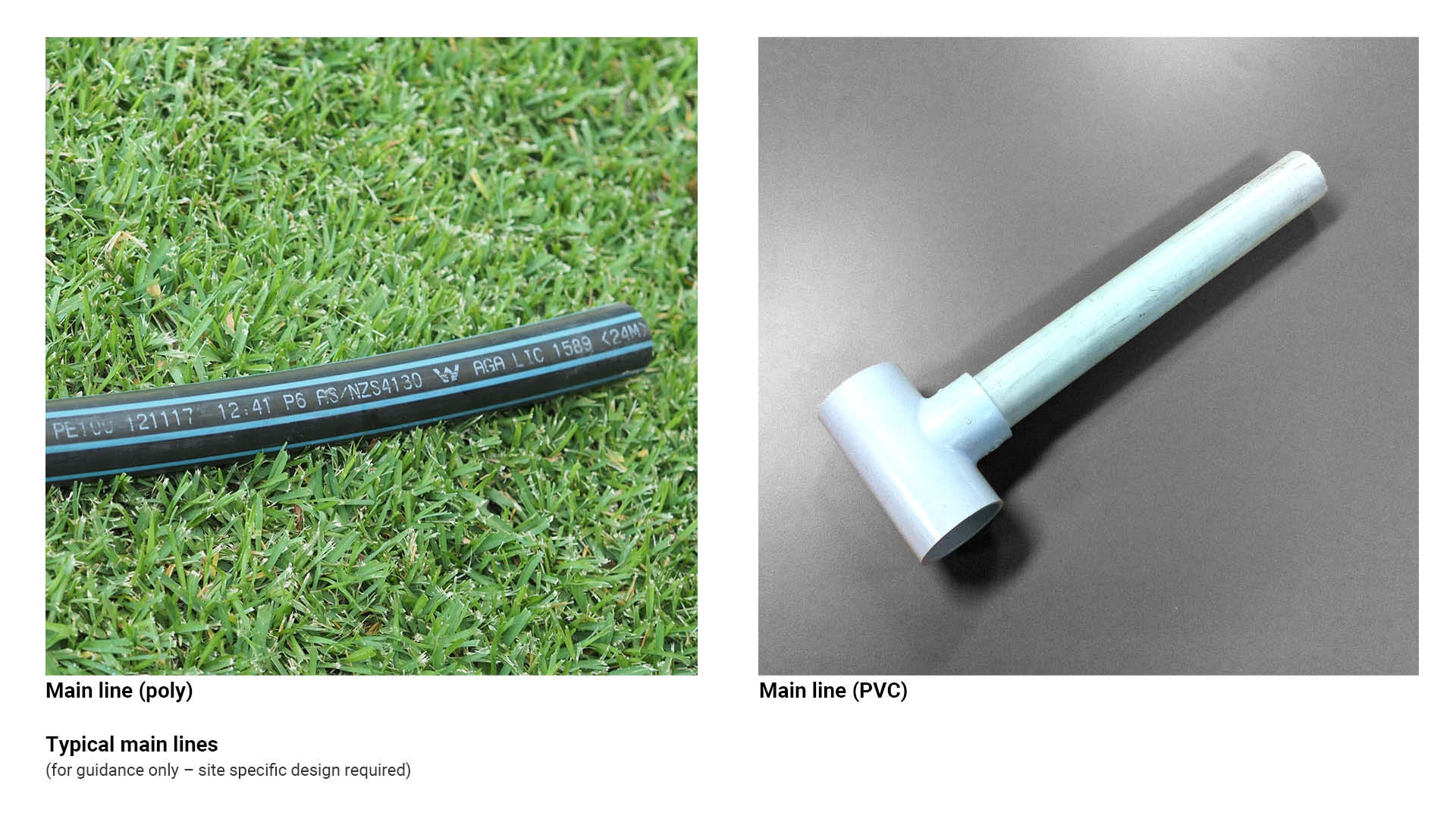
Main supply line and main line pipes
The main supply line and main line pipe is used to distribute water from the supply connection to the valves.
The main line is the water supply line that connects the town mains supply to the irrigation main lines.
- Main lines must be connected to the town mains supply via an RPZ.
- The following components are to be connected to the main line and wired back to the irrigation controller:
- Master valve
- Flow monitoring device.
See the following for further guidance:
- Figure 11: Typical main lines
- Table 3: Pipework (lines) types.
Figure 11: Typical main lines
Lateral line
The lateral pipes are used to distribute water from the solenoid valves to sprinklers and drip manifolds.
A lateral line is a water supply line connected to the main supply line via an electrical solenoid valve and isolation valve.
- Lateral lines have rotors attached directly via an articulated riser and must be designed to allow for consistent pressure to all rotors on the line.
- Individual lateral lines with rotors attached are commonly referred to as ‘stations’ or ‘banks’ of sprinklers.
- Where lateral lines used in turf or gardens run under permanent infrastructure, they are to be class 16 poly pipe.
See the following for further guidance:
- Figure 12: Typical lateral lines
- Table 3: Pipework (lines) types.
Figure 12: Typical lateral lines
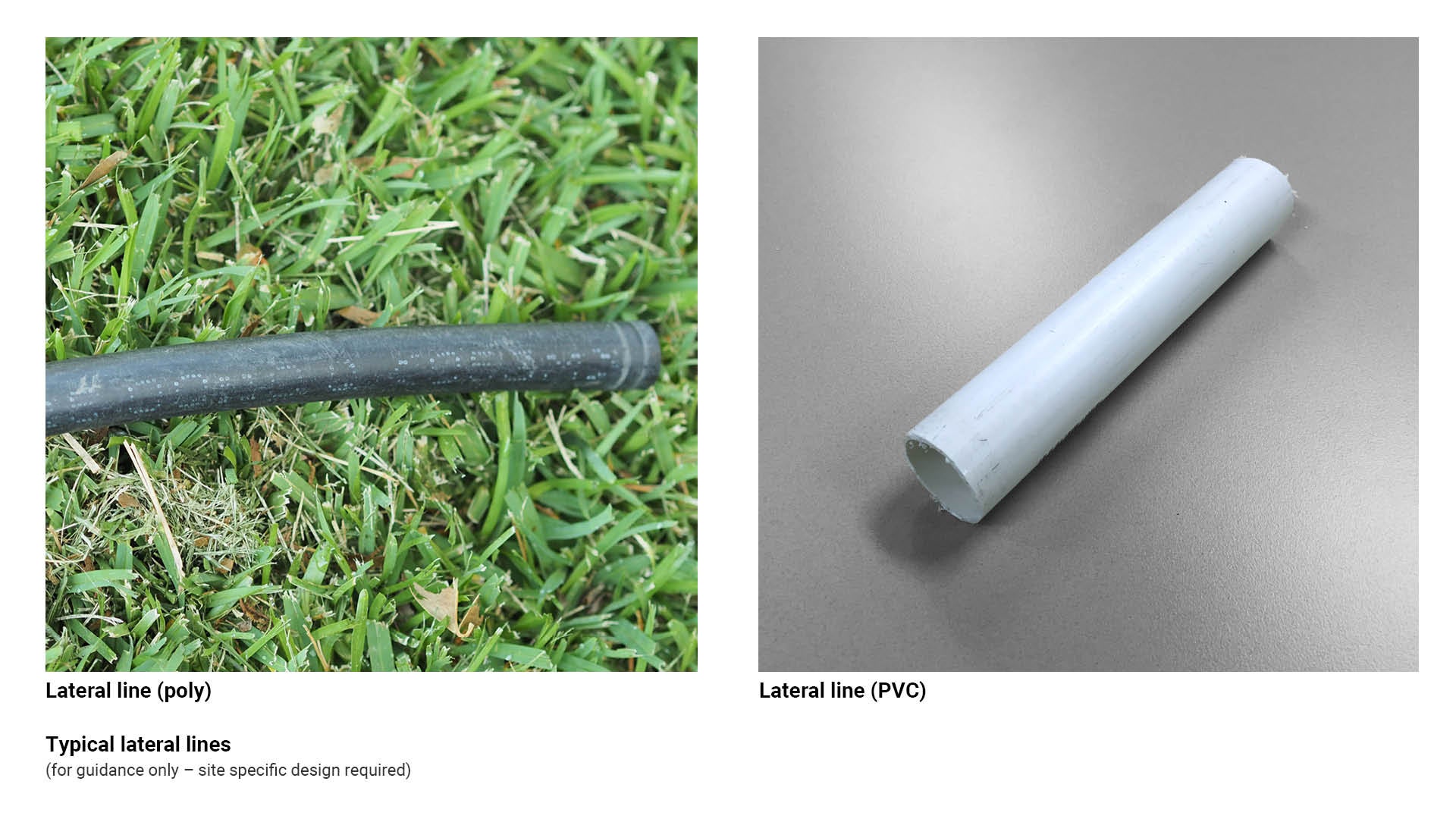
Table 3: Pipework (lines) types
Irrigation type | Recommended use/application | Key consideration |
LDPE poly pipe (19 mm) 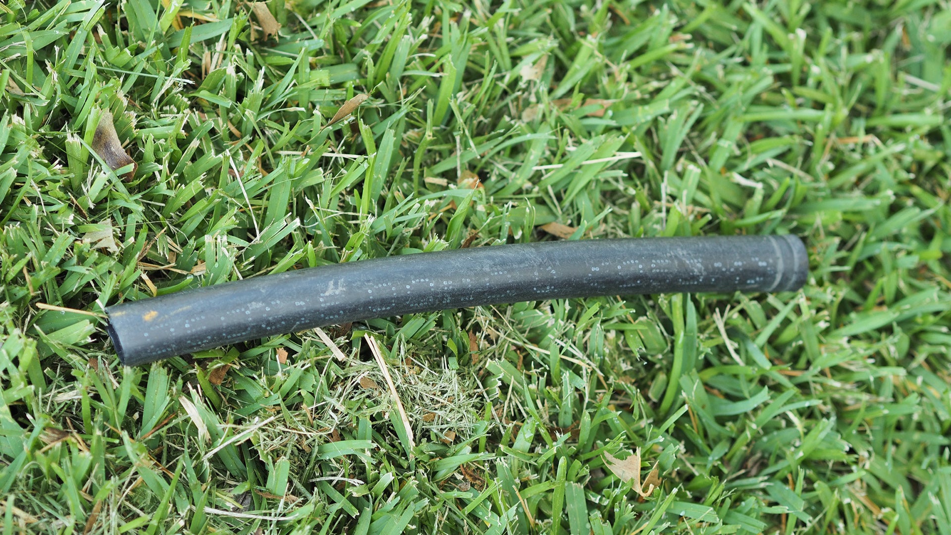 | Lateral lines. |
|
25 mm LDPE poly 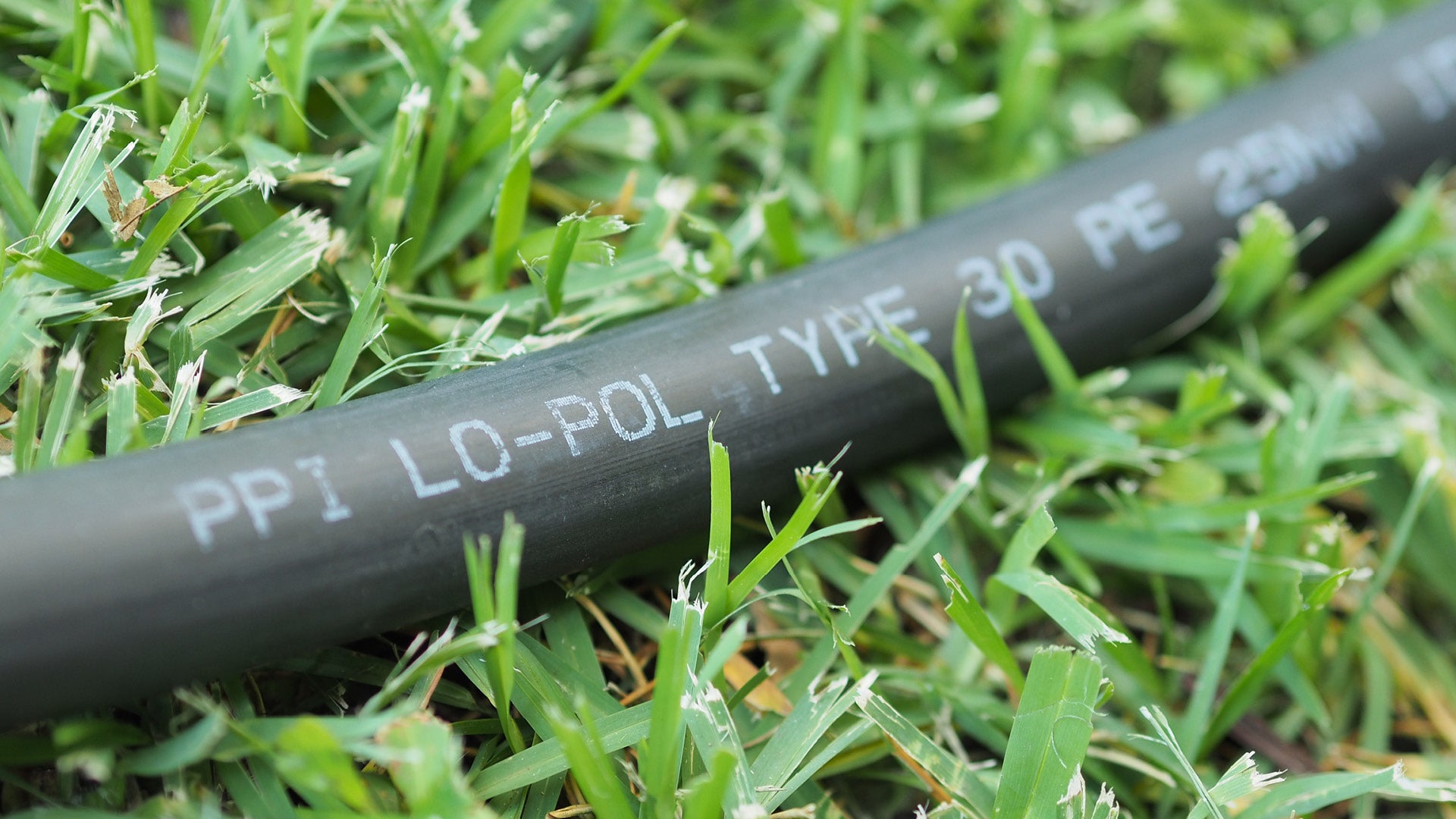 | Lateral lines. |
|
32 mm OD poly main line class 12.5  |
|
|
25 mm OD poly mainline class 12.5 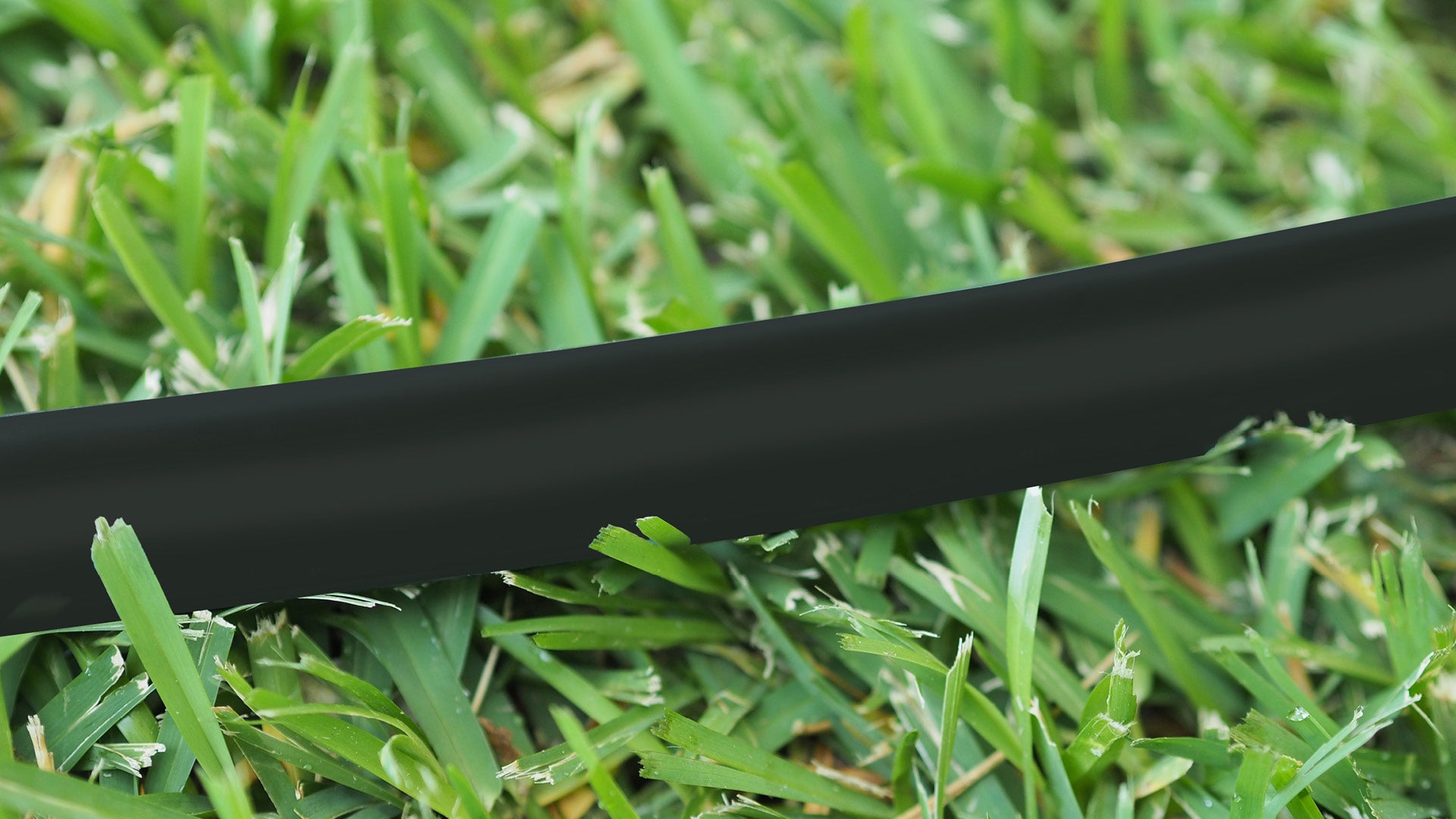 |
|
|
50 mm OD poly mainline class 12.5 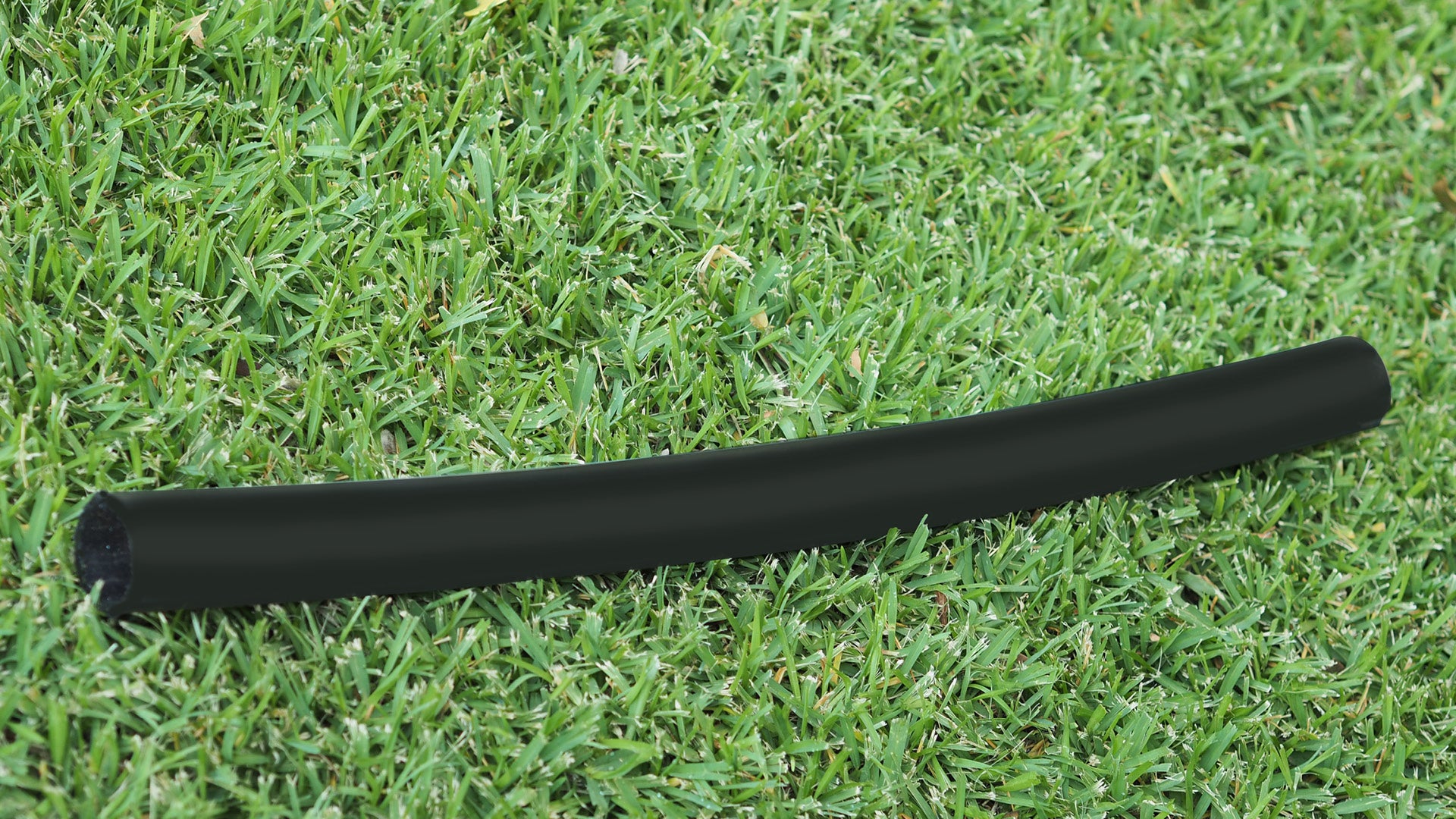 |
|
|
Valves
In an irrigation installation, valves are devices used to control water flow.
Generally, most irrigation systems consist of both manual (ball or gate valves) and automatic valves (solenoid valves).
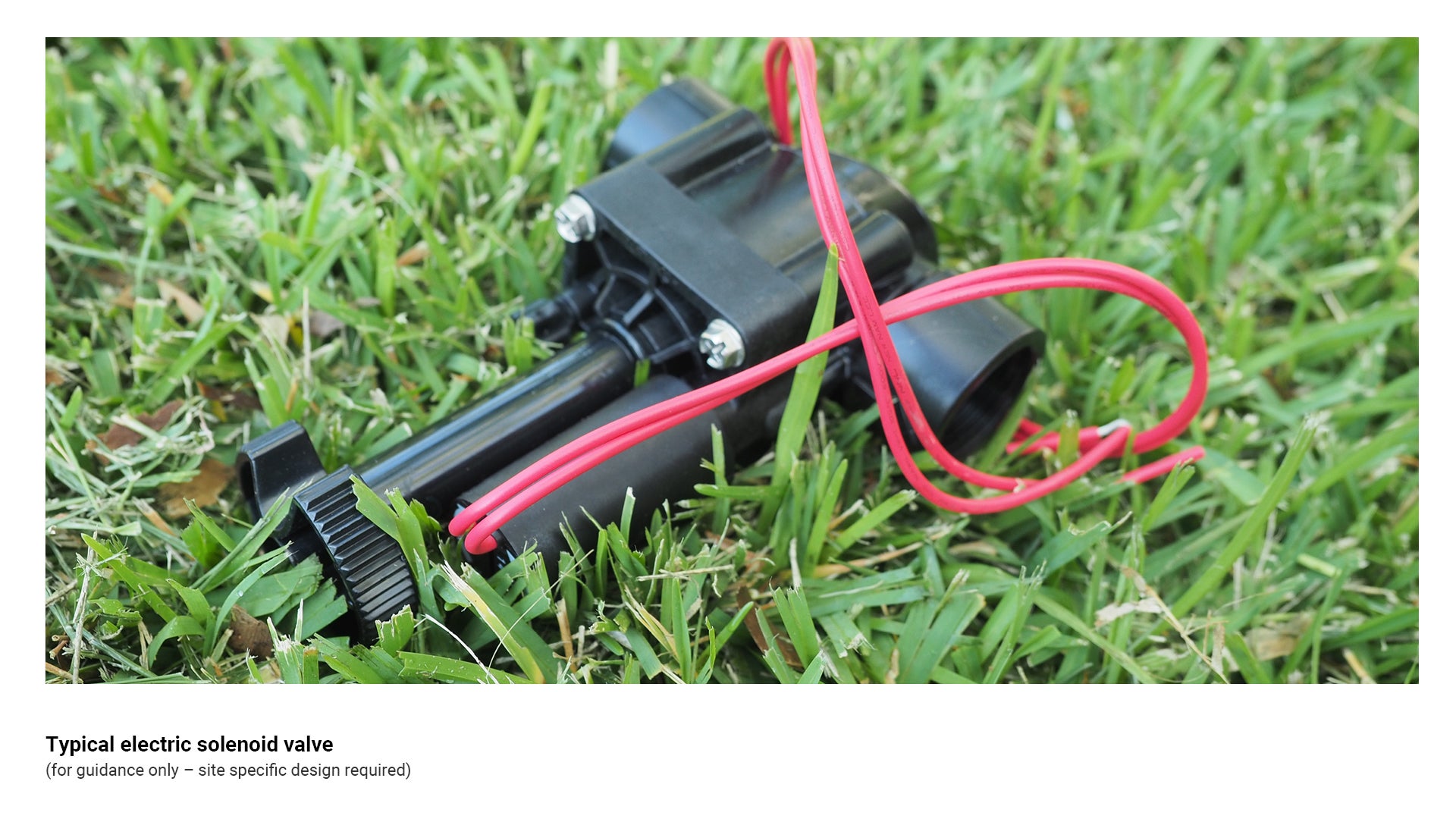
Automatic control valves and electric solenoid valves
An electric solenoid valve is a device that opens and closes via an electrical circuit and allows water to flow through a pipe in a designated direction of flow.
- Solenoid valves are electrically actuated, normally closed hydraulic valves.
- These valves are connected via multi-core irrigation wire to an automatic irrigation controller. The type of multi-core wire used is to be determined by the requirements specified in the irrigation design.
- Electric solenoid valves are available with the following features:
- Flow control – to allow for adjustment of water flow through the valve.
- Pressure regulation device – can be set to deliver a constant downstream pressure to the sprinklers / emitters regardless of pressure variations in the mainline.
See the following for further guidance:
- Figure 13: Typical electric solenoid valve
- Table 4: Valve types.
Figure 13: Typical electric solenoid valve
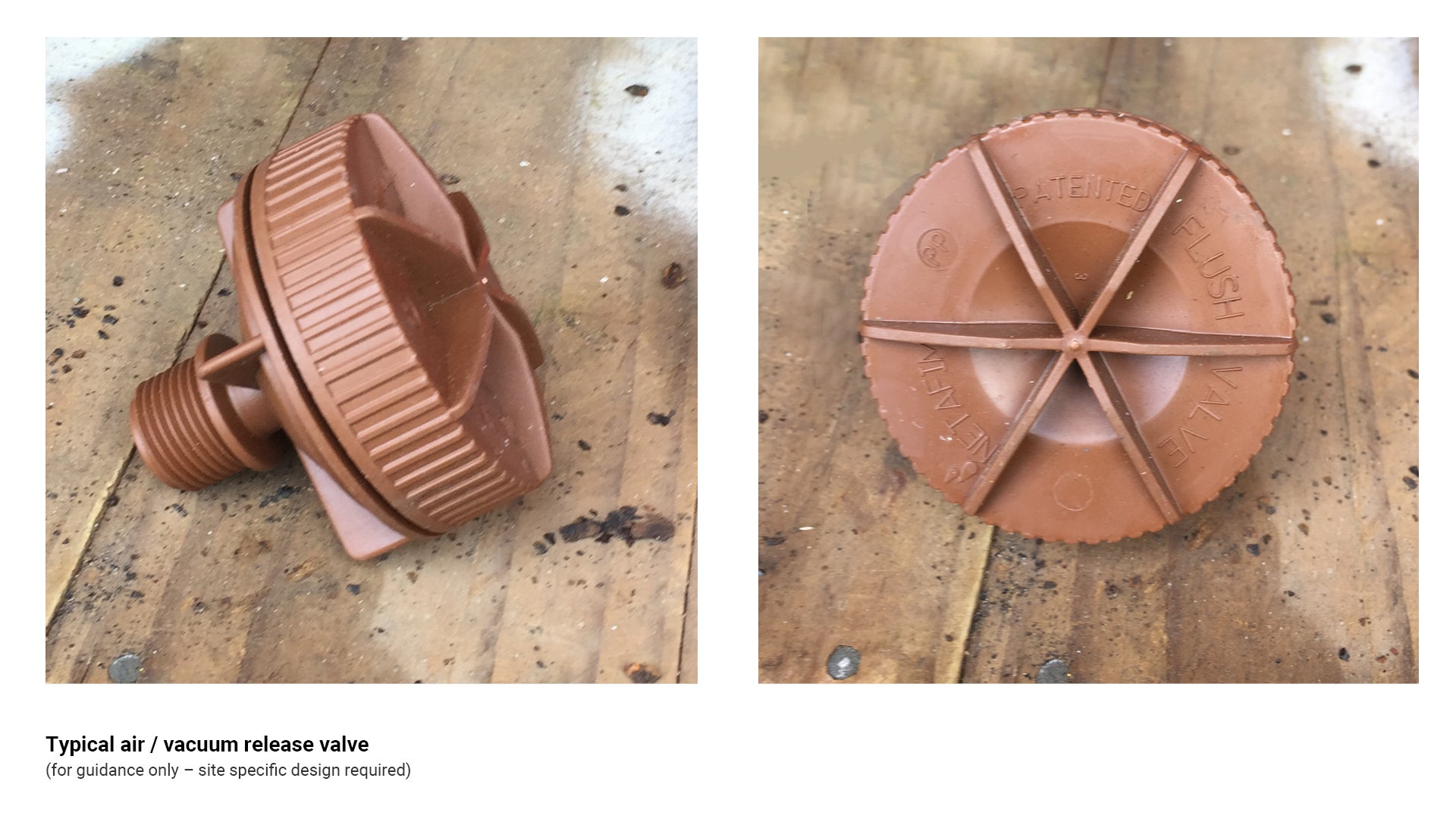
Air/vacuum release valves (automatic)
Air/vacuum release valves are two way valves allowing air to be vented from the pipework when being filled with water, or allowing air to enter the pipework when water is being drained from the main. This prevents a vacuum occurring, preventing potential damage to irrigation systems and fittings.
- Air release valves are to be installed at the highest point/s of the irrigation system.
- To ensure only clean air enters the system, air release valves are to be installed in a suitably sized valve box with gravel drainage to just below the air intake.
See the following for further guidance:
- Figure 14: Typical air/vacuum release valve.
- Table 4: Valve types.
Figure 14: Typical air/vacuum release valve
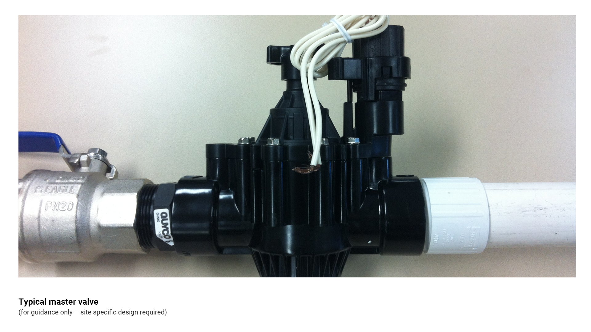
Master valve
A master valve is an electrical solenoid valve which controls water flow to the irrigation main line. It is installed at the supply point, immediately downstream of the backflow device.
- A master valve will greatly reduce any water loss due to leaks within an irrigation system because no water can enter the main line unless the master valve is opened during scheduled irrigation. Also, if you damage the irrigation main line, a master valve will control water loss so the main can be repaired without shutting off the water supply.
See the following for further guidance:
- Figure 15: Typical master valve.
- Table 4: Valve types.
Figure 15: Typical master valve
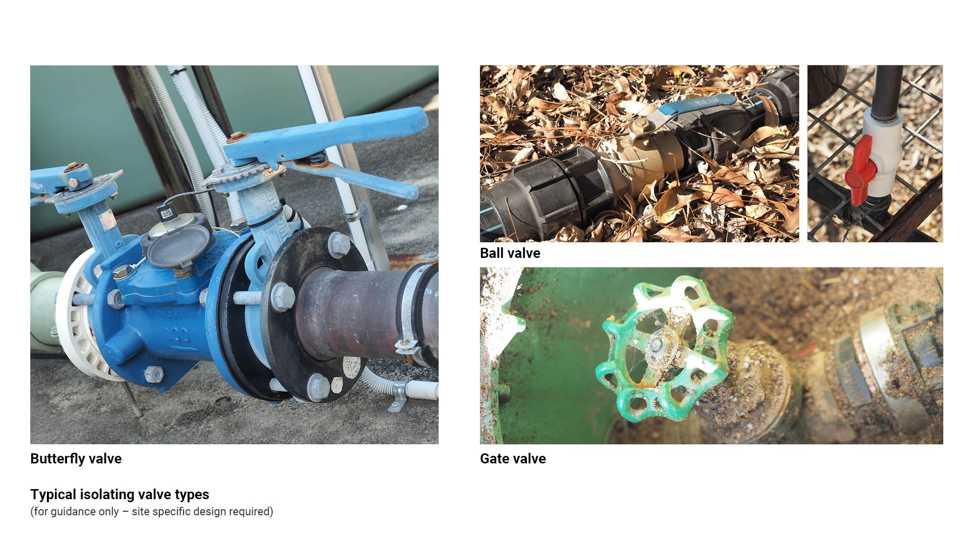
Isolating valves (manual)
Isolation valves are used to isolate all or part of an irrigation system for maintenance or quick repairs without the need for shutting down the solenoid valve.
- Isolation valves are installed immediately downstream of the solenoid valve on each lateral line.
- Common types of isolation valves are:
- Ball valves
- Gate valves
- Butterfly valves.
- Isolation valves must be WaterMark approved. General industry valves must NOT be used.
See the following for further guidance:
- Figure 16: Typical isolating valve types.
- Table 4: Valve types.
Figure 16: Typical isolating valve types
Quick coupling valves
Isolatable, secure manual access to the mainline for hand watering purposes.
See the following for further guidance:
- Figure 17: Typical quick coupling valve.
- Table 4: Valve types.
Figure 17: Typical quick coupling valve
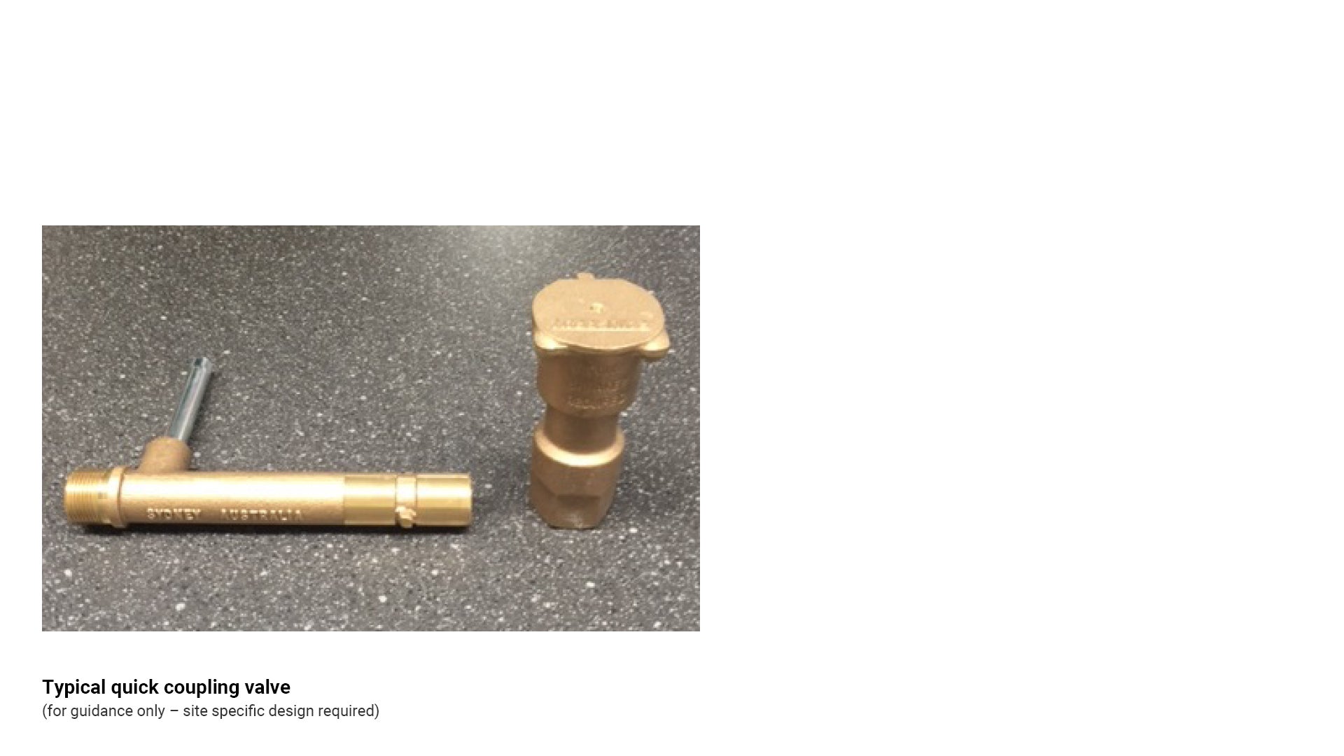
Table 4: Valve types
Irrigation type | Recommended use/application | Key consideration |
25 mm solenoid valve 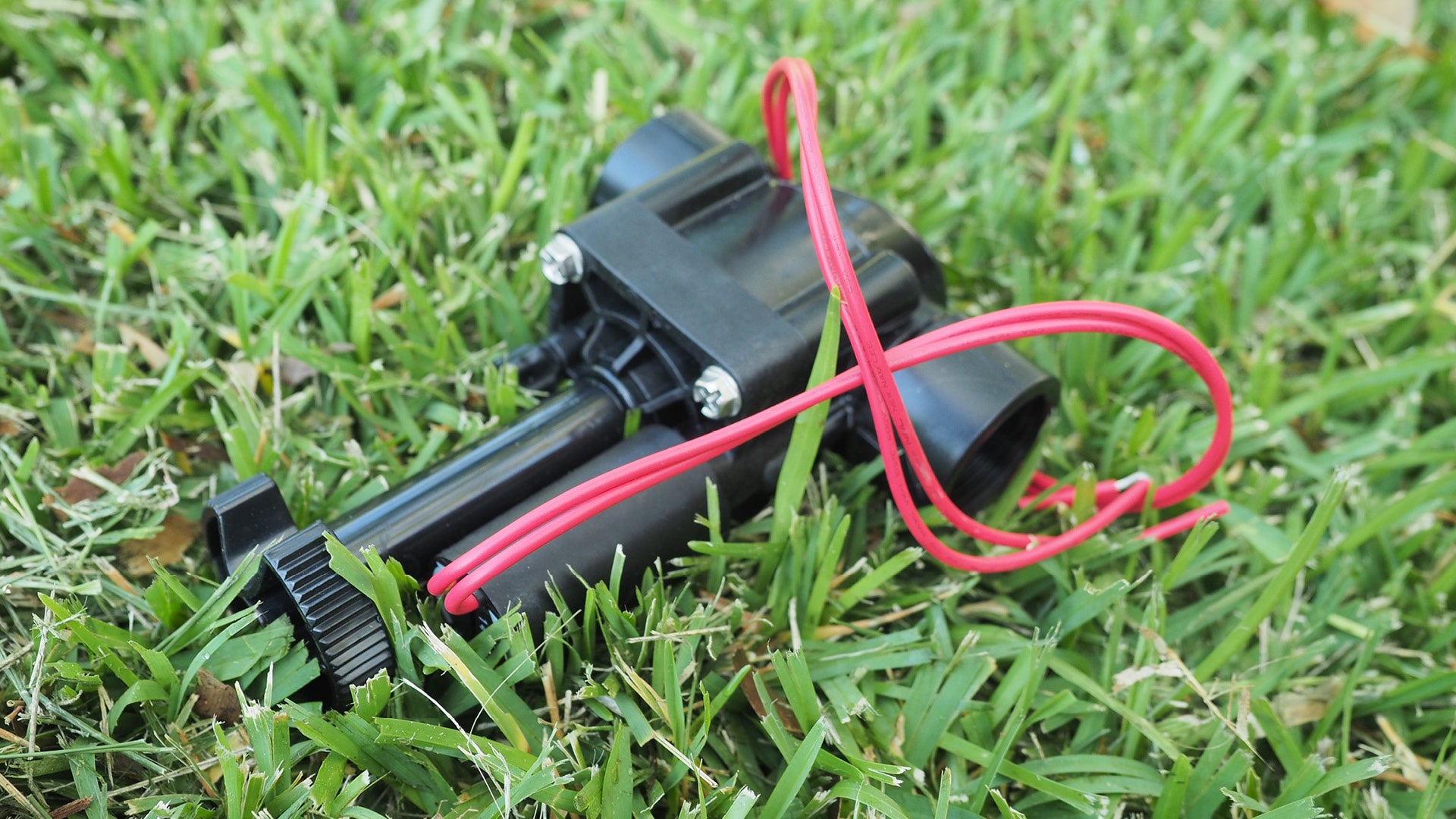 | Used for the automatic or manual control of water flow in an irrigation system. |
|
Master valve 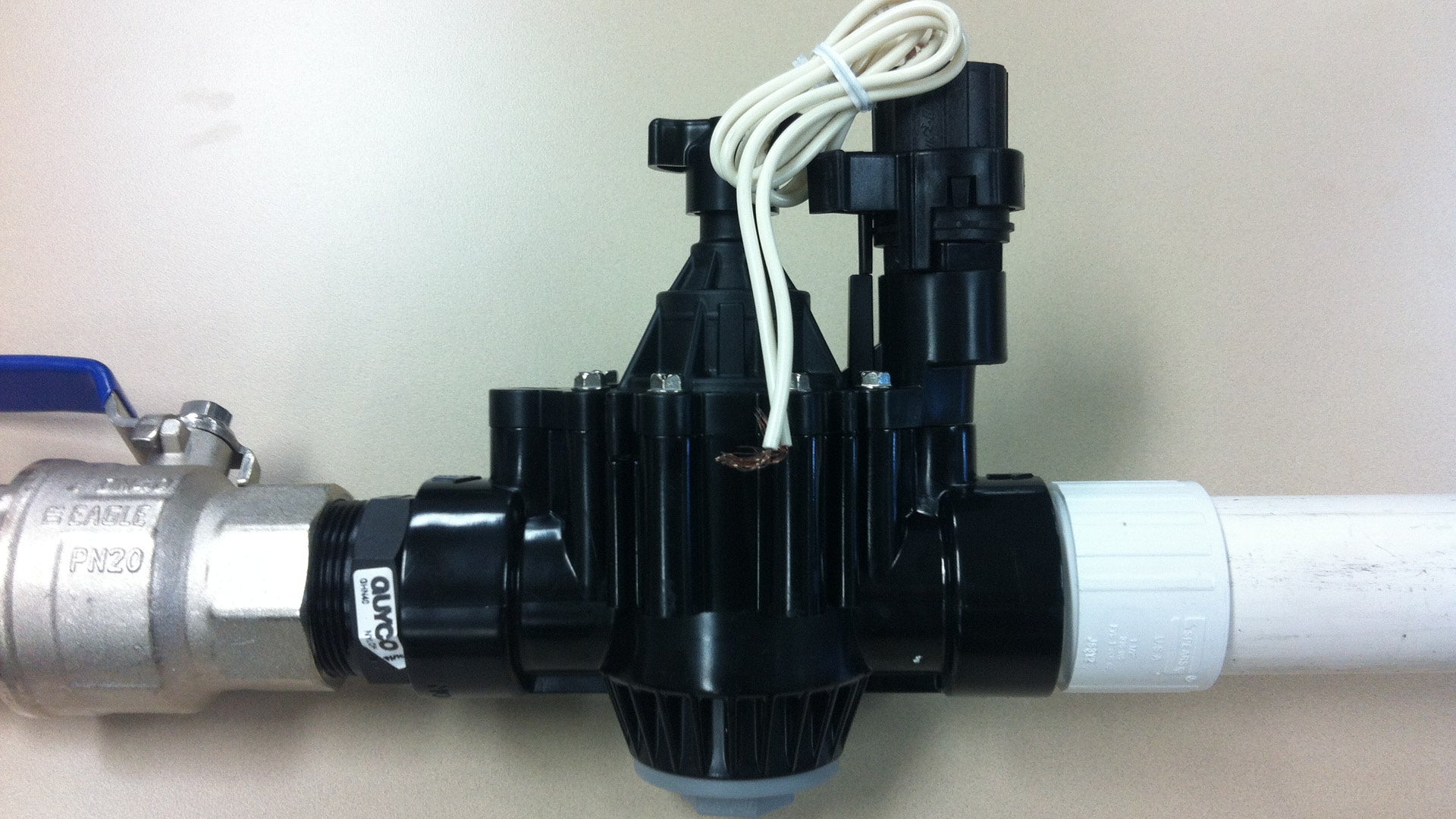 | Allows water to supply the system ONLY when automatic irrigation controller is used. | Acts as a failsafe in high vandalism scenarios, or where unauthorised use may occur. |
Mainline/solenoid isolation valve (WaterMark approved) 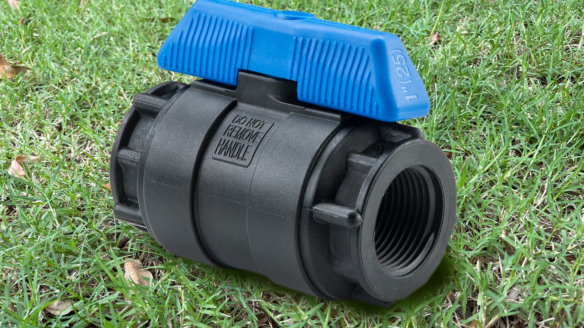 | Used on all mainline isolation, and upstream of solenoid applications. |
|
25 mm poly ball valve class 16 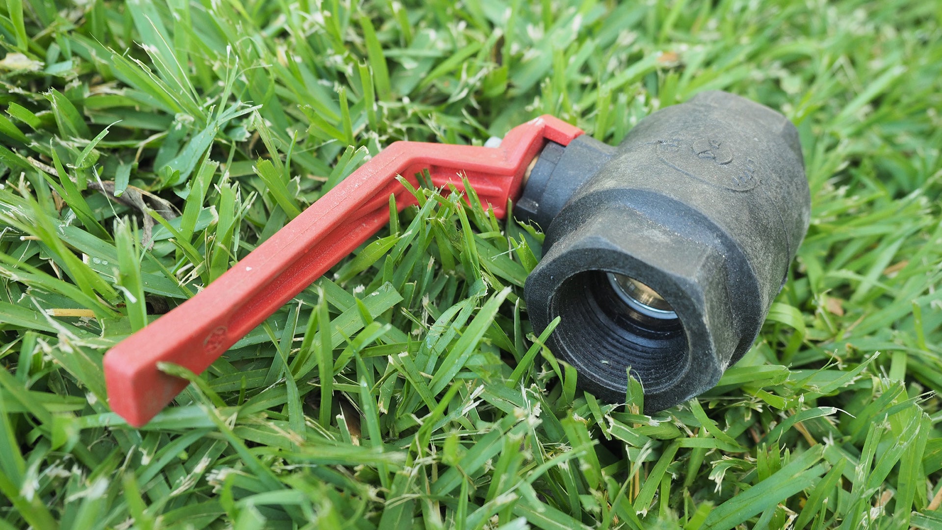 | Used for shut off and isolation applications. |
|
Brass ball valve (50 mm) 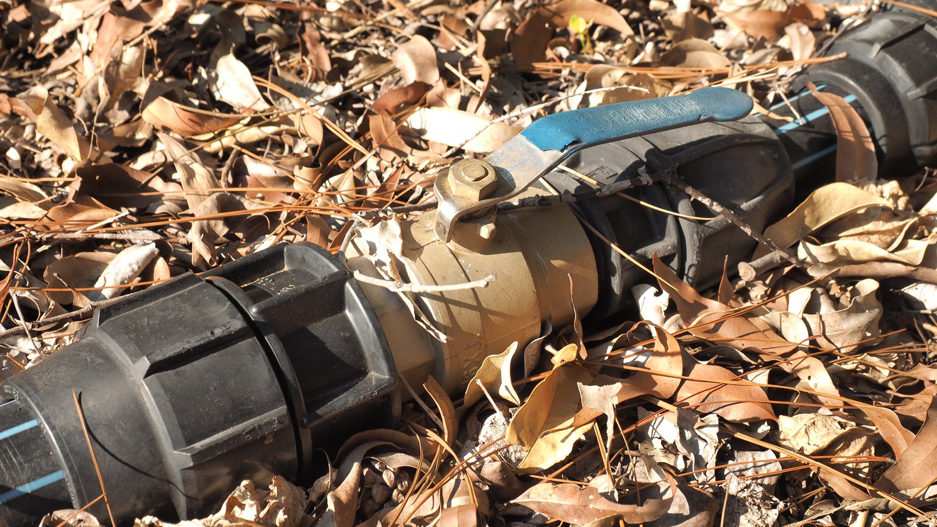 | Used for shut off and isolation applications. |
|
PVC Ball valve 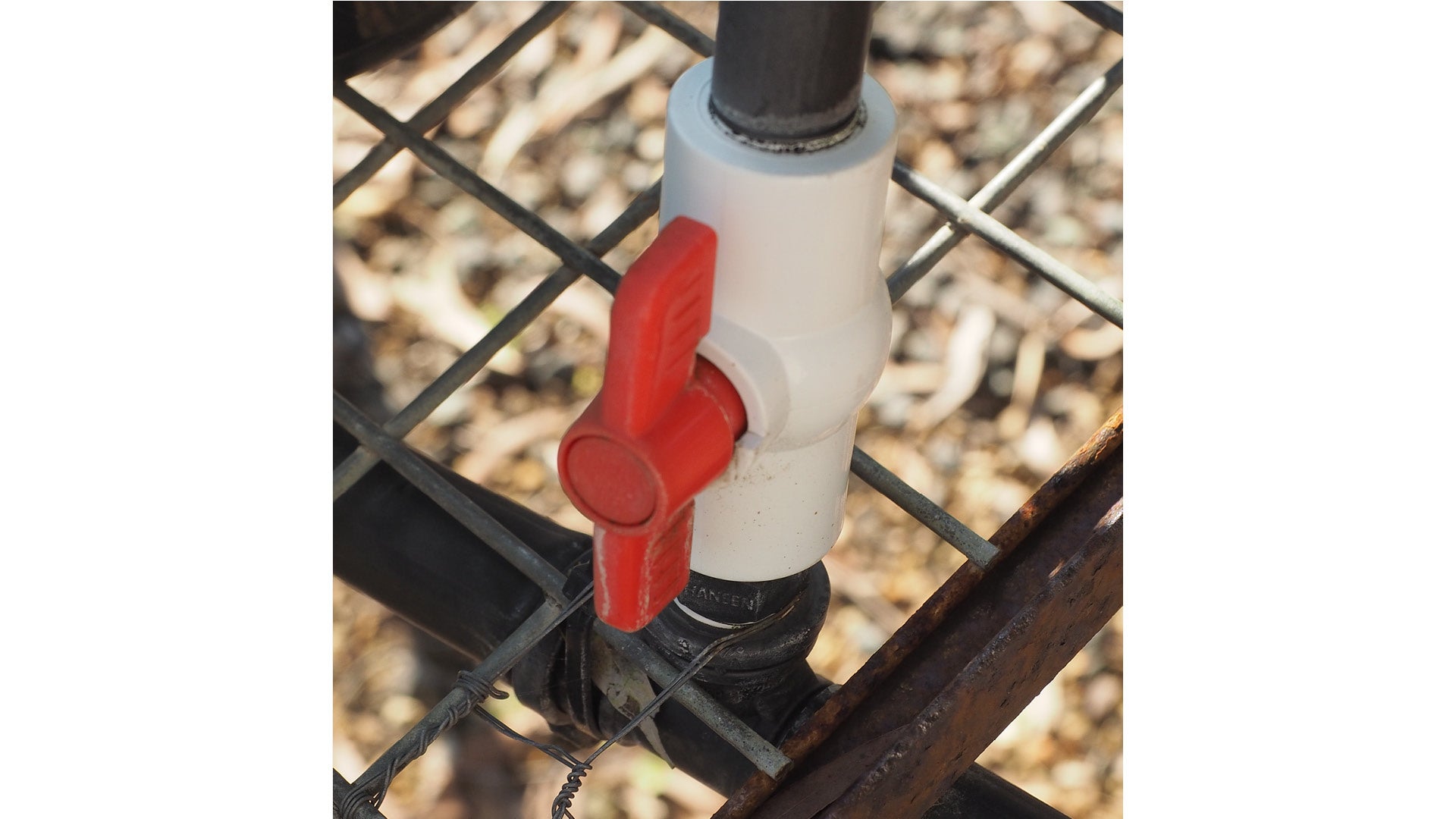 | Used for shut off and isolation applications. |
|
Brass gate valve 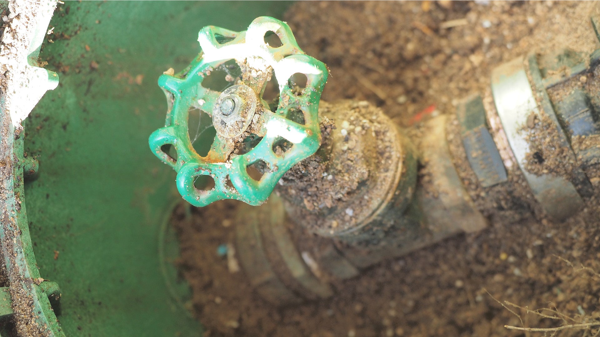 |
|
|
Butterfly valve 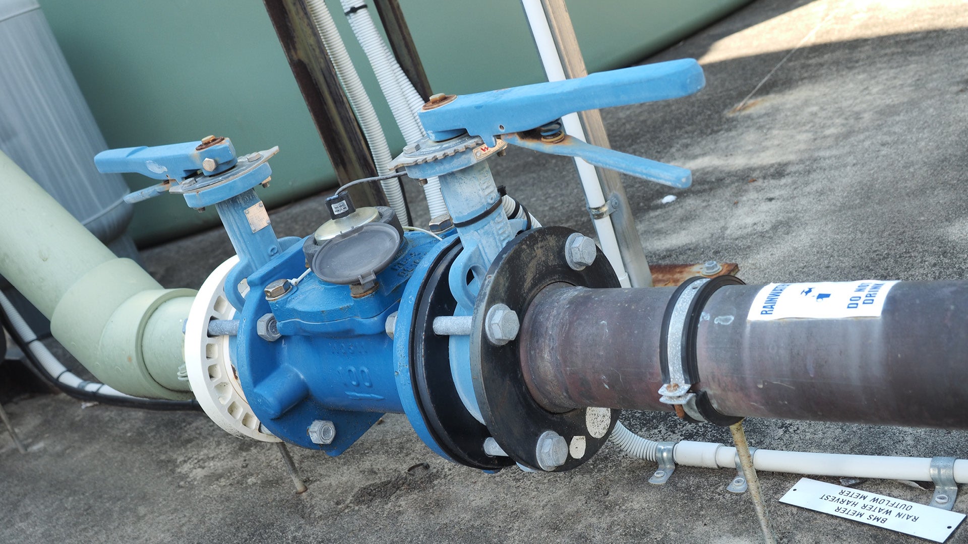 | Isolating or regulating flow. |
|
Pressure reducing valve 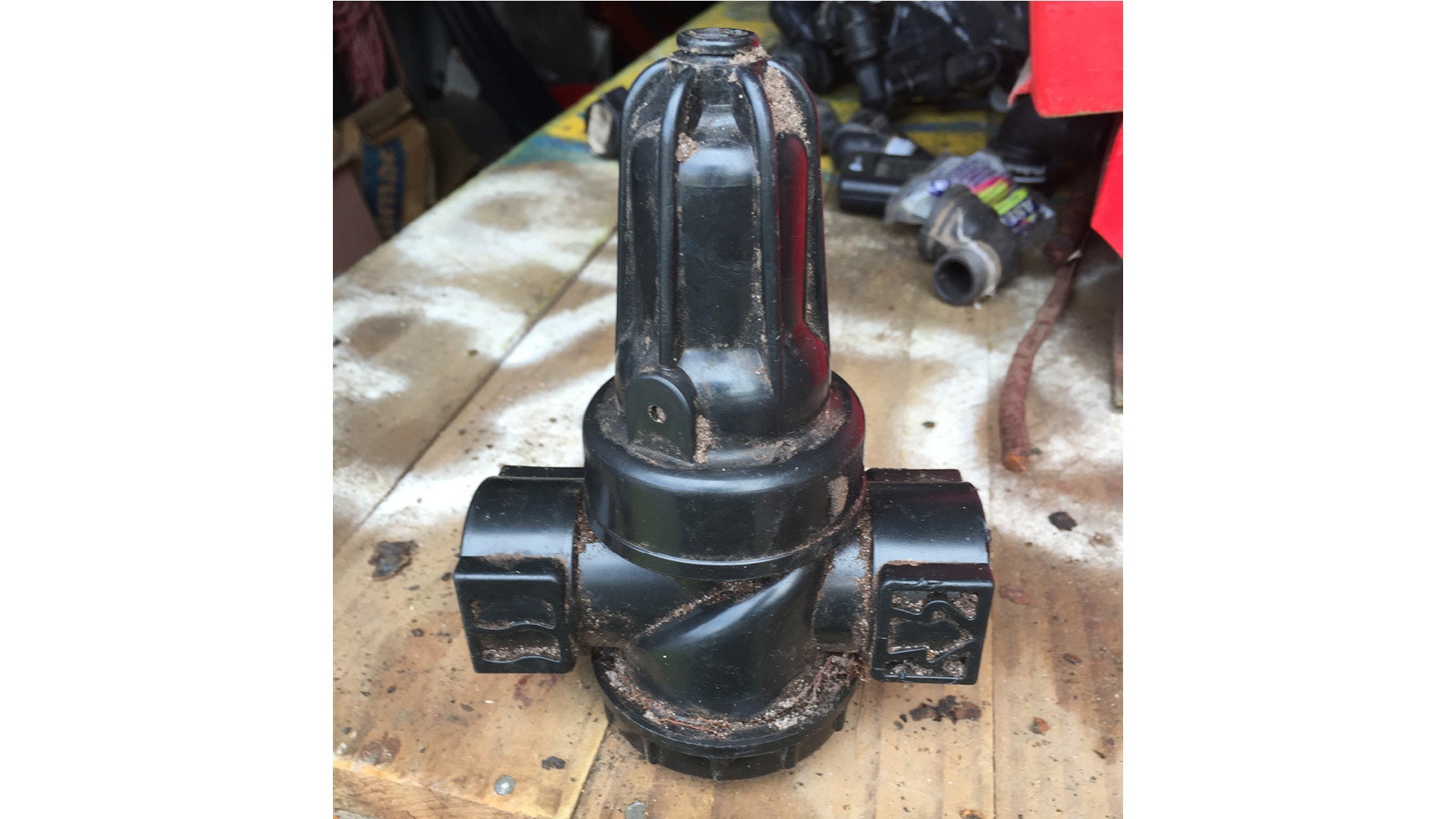 | Regulates pressure to compensate for fluctuations from mains supply. | Adjustable PSI. |
Air relief valve 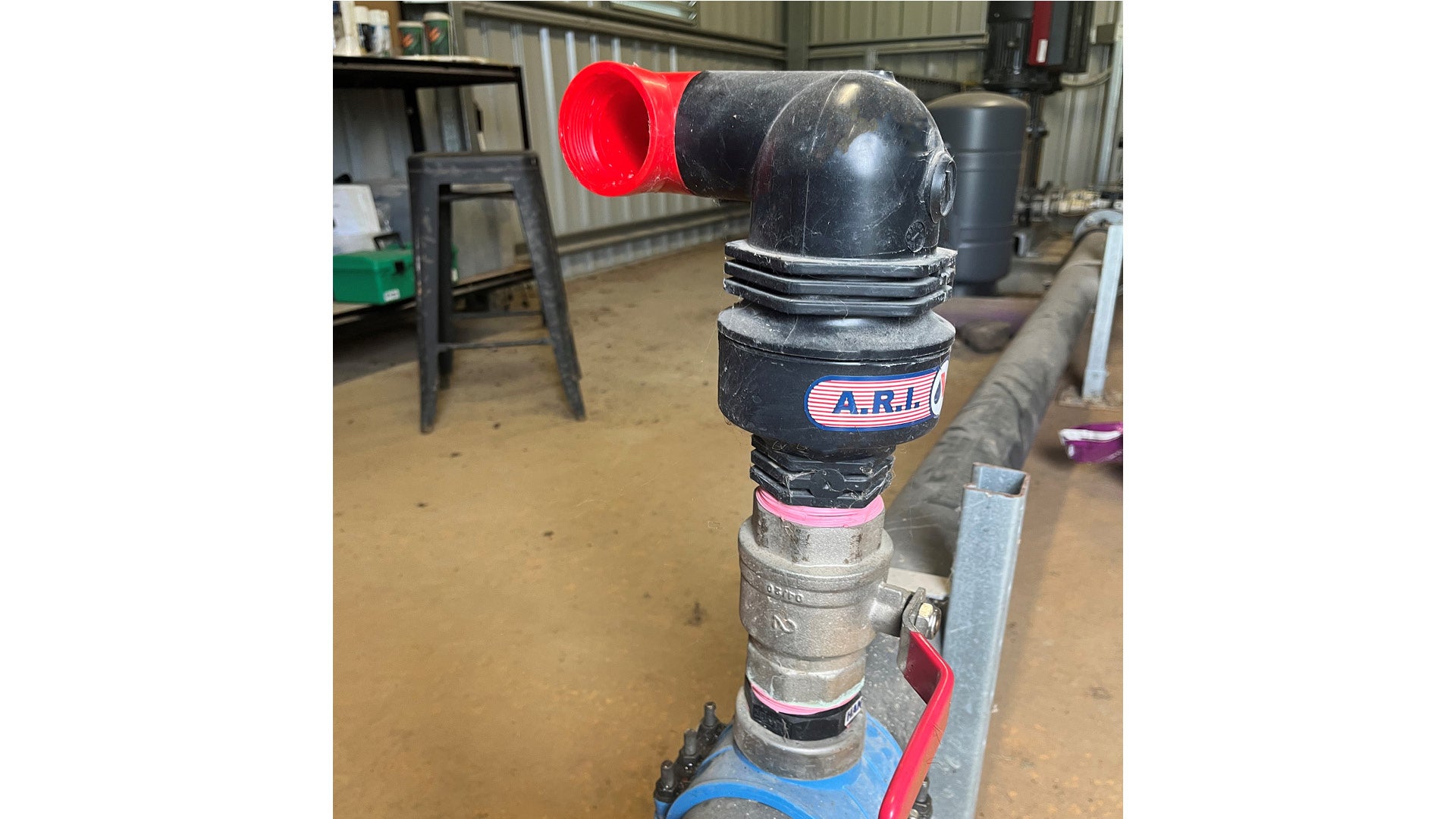 |
|
|
Line flushing valve 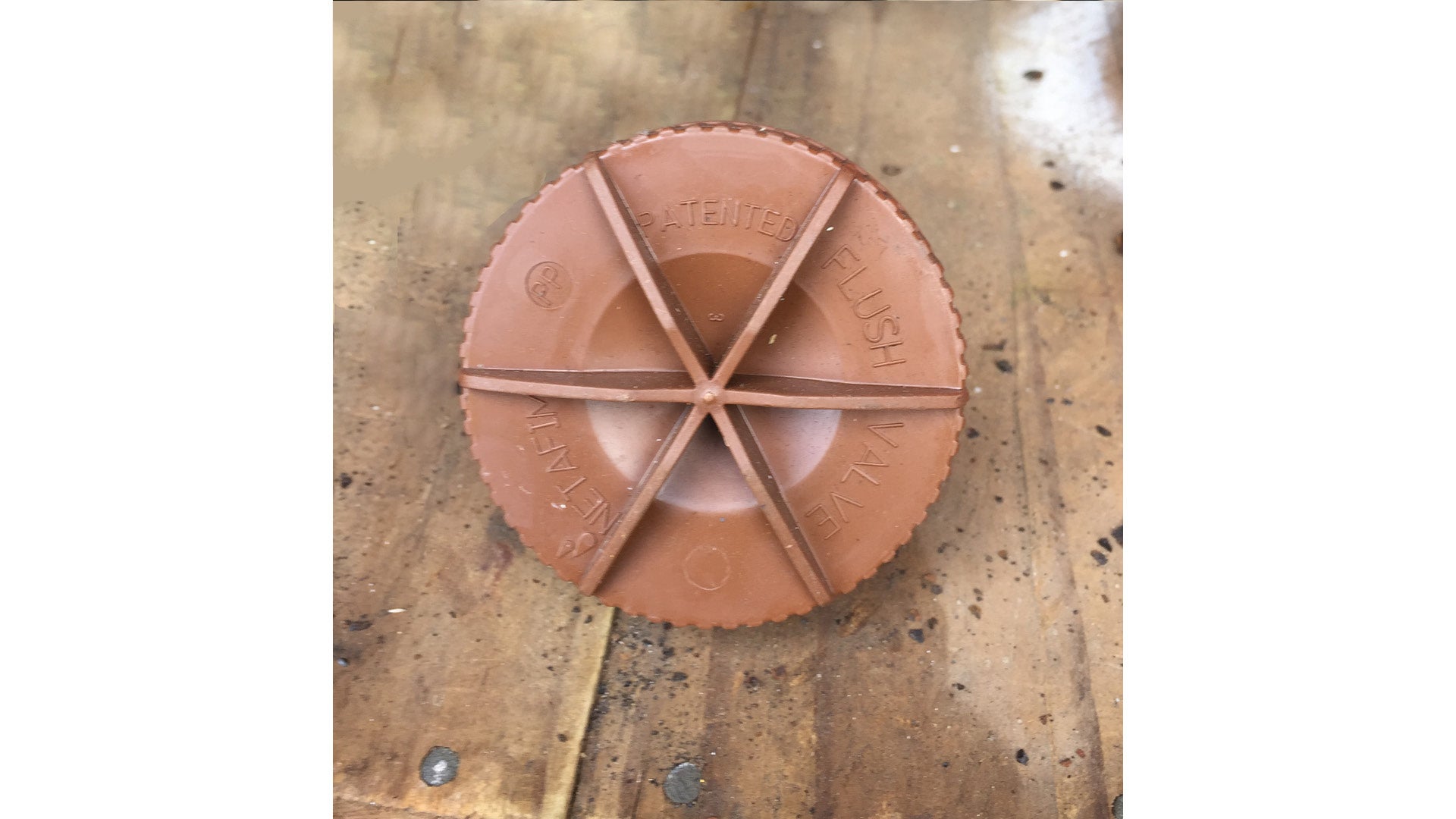 |
|
|
Quick release valve (QCV) 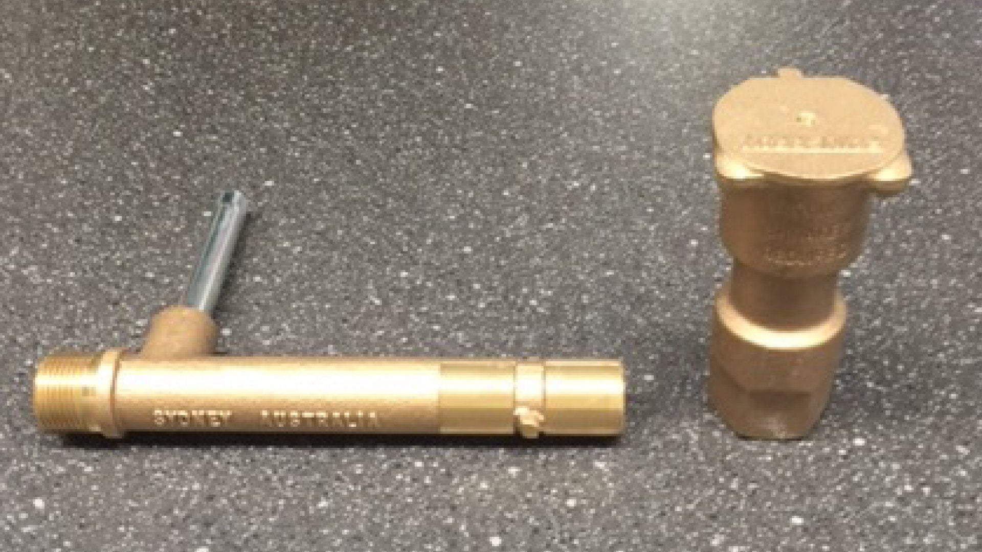 | Quick water access. |
|
Valve boxes
Irrigation valve boxes are installed below ground with the lid flush to the finished surface level of the surrounding landscape. They contain electric solenoid valves, isolation valves and wire loops.
- Irrigation boxes are available in different sizes and shapes according to the type and size of the components contained within.
- Where specified, valve boxes should be lockable.
- Valve boxes:
- must have support blocks
- must have geofabric to stop soil ingress
- must not be sitting on pipe or cables.
See the following for further guidance:
- Figure 18: Typical valve boxes
- Table 5: Valve box types.
Figure 18: Typical valve boxes
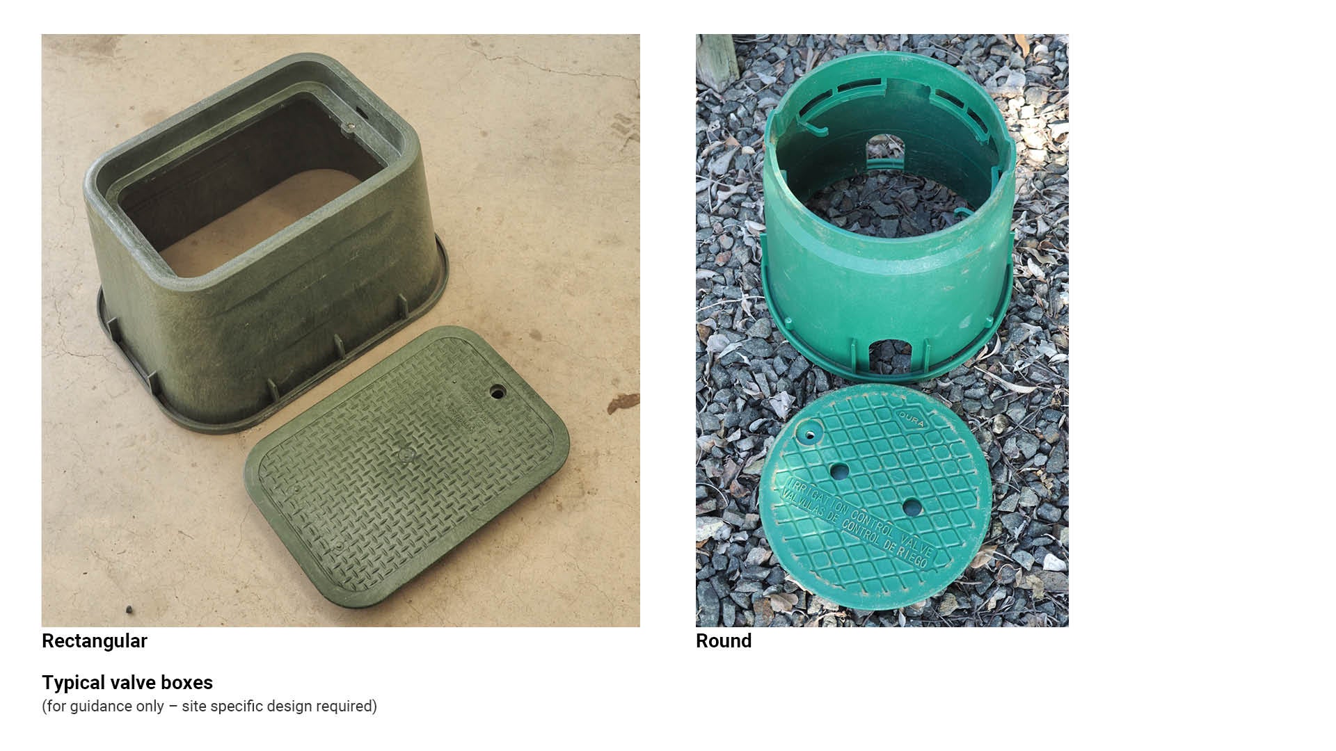
Table 5: Valve box types
Irrigation type | Recommended use/application | Key consideration |
Valve box - round 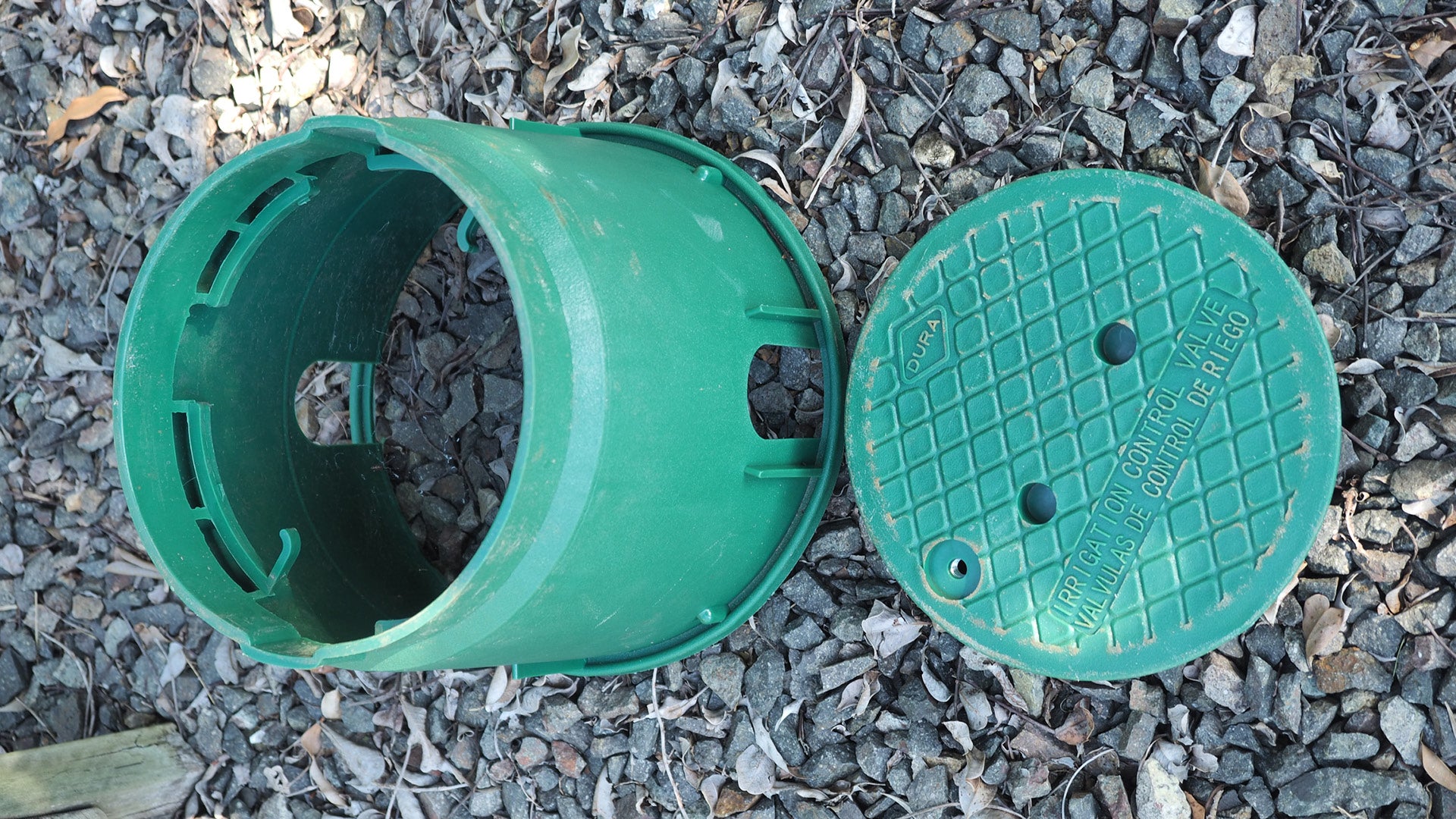 | Suitable for housing the following:
|
|
Valve box - rectangular 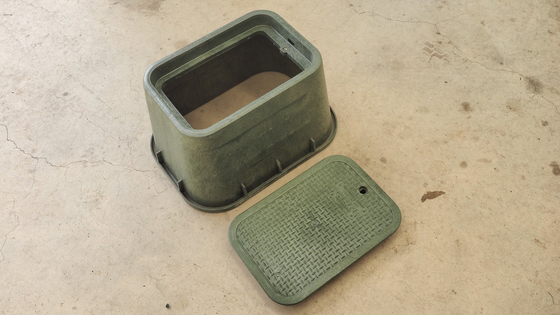 | Suitable for housing the following:
|
|
Emitters
An emitter is a device used to distribute water in an irrigation system. The two main types of emitter are:
- Spray emitters – directing water droplets into the air to cover a larger area, such as micro sprays used in micro irrigation.
- Drip emitters – enable water to be delivered directly to the root zone.
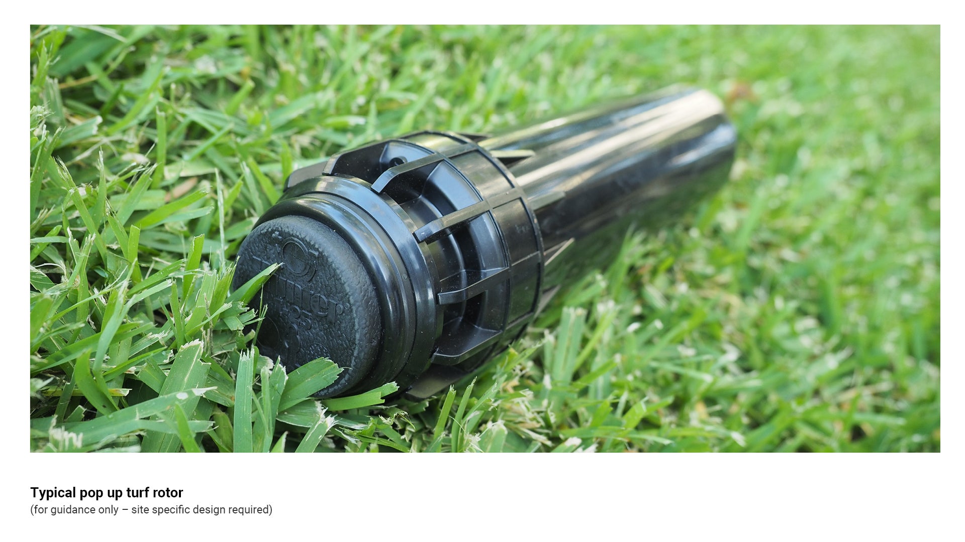
Pop up turf rotors
Pop up spray heads are designed to supply a continuous stream of water. They are possibly the most widely used irrigation head and are typically used for residential and small commercial sprinkler systems.
- There are two types available:
- Stationary sprays
- Rotating heads (rotors).
- Heads are fitted with nozzles in a variety of differing designs.
- These nozzles are designed to distribute water in a variety of patterns to fit the contours of the landscape.
- Each nozzle is designed for a specific spray pattern, for example:
- Full arc – 360°
- Half circle – 180°
- Quarter circle – 90°.
- Some rotors have finer adjustments, allowing for any degree of arc adjustment.
- All sprinklers installed on each station shall be matched precipitation to ensure an even distribution of precipitation is applied across the entire station area. Only sprinklers with a matched precipitation rate shall be grouped to operate together on a valve section. Similarly, only stations with identical precipitation rates may be grouped to operate as a simultaneous station group (SSG) at the irrigation controller.
See the following for further guidance:
- Figure 19: Typical pop up turf rotor
- Table 6: Emitter types.
Figure 19: Typical pop up turf rotor
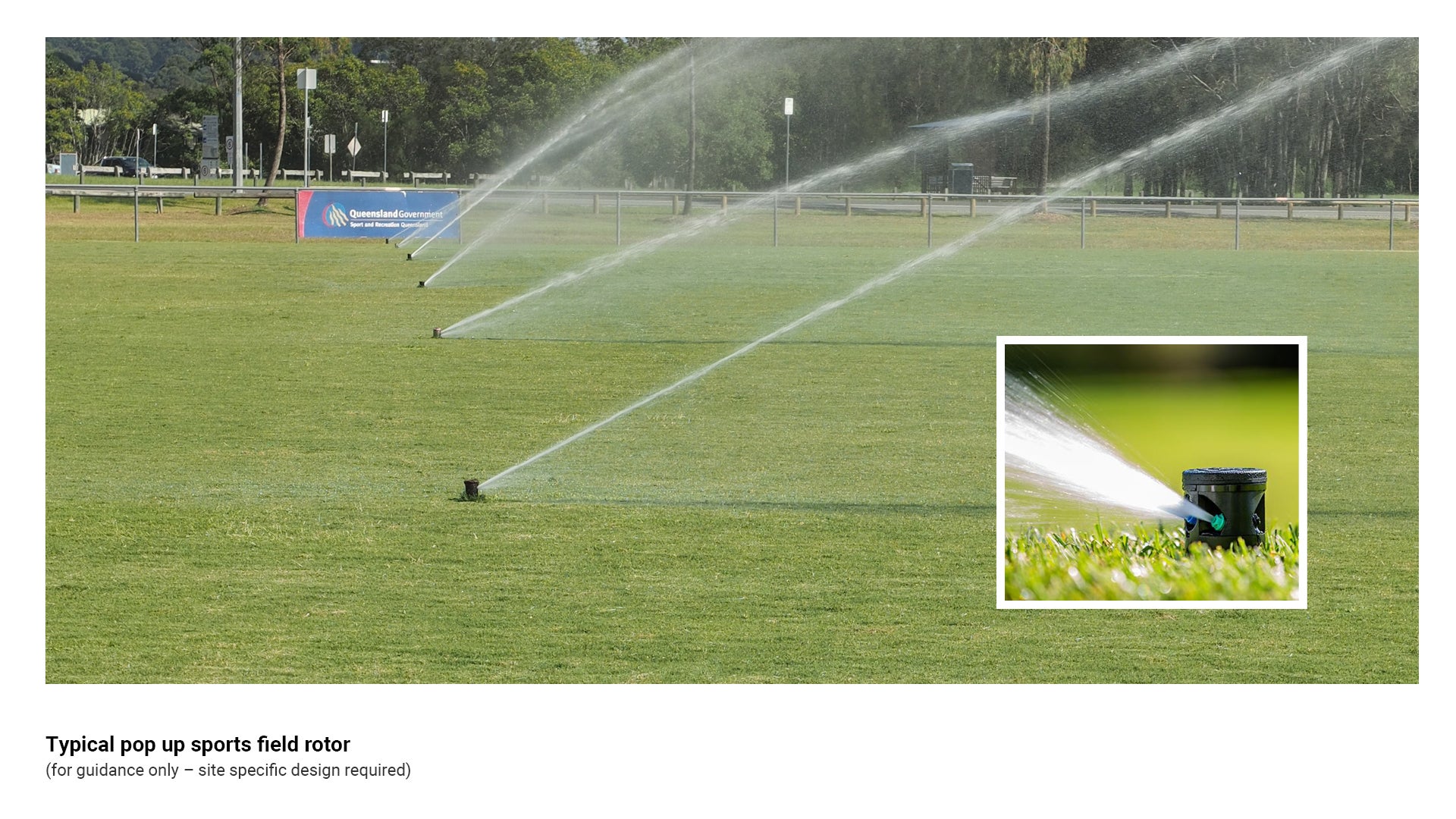
Pop up sports field rotors
Sports field rotors are basically the same as turf rotors, however they are larger, have the capacity to cover a large area, and distribute a larger amount of water in a relatively short space of time.
- Due to the increased capacity of the selected rotor, the rest of the system, including the mains connection point and RPZ need to be of a larger size as per the manufacturer’s recommendations.
See the following for further guidance:
- Figure 20: Typical pop up sports field rotor.
- Table 6: Emitter types.
Figure 20: Typical pop up sports field rotor
Pop up shrub sprays
High pop rotors are mounted above ground level on a vertical riser. This allows the sprinkler to be elevated above the level of the plants, where it can spray water over them. Shrub-type sprinklers are most often used in areas with tall, dense shrubs.
- Some advantages of this type of emitter are:
- Damaged heads can be easily identified and repaired.
- The system is very robust, and can withstand damage caused by plant replacement and root infiltration from large trees and shrubs.
- This type of emitter is easily visible, and can therefore be prone to vandalism in areas frequented by the public.
Sub-surface drip irrigation (drip emitter)
A drip irrigation system delivers water directly to the root zone of a plant, where it seeps slowly in to the soil. Almost no water is lost through surface runoff or evaporation, and soil particles have plenty of opportunity to absorb and hold water for plants.
- Council DOES NOT support the use of drip irrigation systems in locations other than planter boxes
- Drip irrigation has limitations where there is a requirement to apply treatments to plants that require foliar application, as the system does not have the capability to wash products from the leaves of the plant.
- Drip irrigation can be easily damaged through replacement of damaged plant stock and general maintenance. This is due to the nature of the systems design requirements, and the pipework and components not being particularly robust.
- Drip irrigation lines are costly to maintain, can become easily blocked and damaged lines can be difficult to locate in mature gardens.
- Most effective in planter boxes where there is a requirement to avoid overspray, where the likelihood of damage due to excavation is low. Council supports the use of drip irrigation systems in planter boxes.
See the following for further guidance:
- Figure 21: Typical sub-surface drip irrigation.
- Table 6: Emitter types.
Figure 21: Typical sub-surface drip irrigation
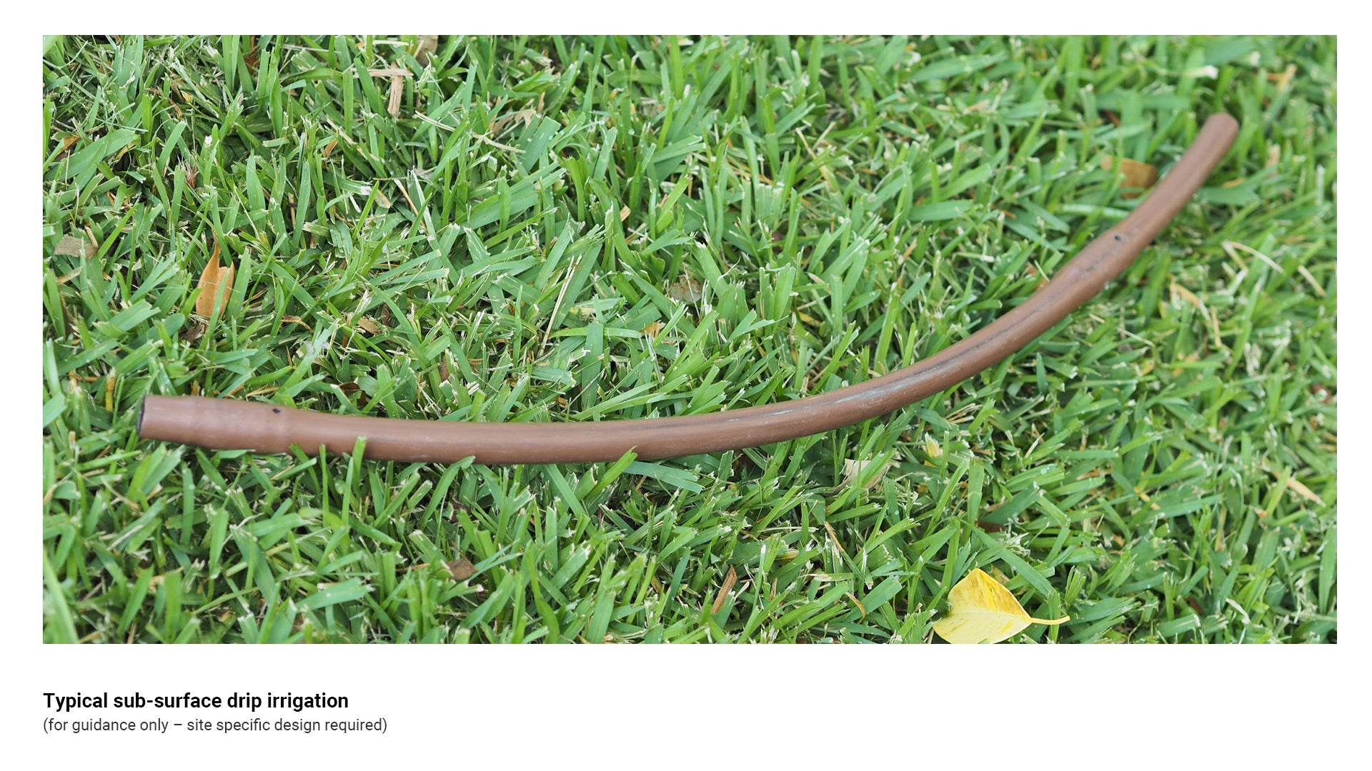
Table 6: Emitter types
Irrigation type | Recommended use/application | Key consideration |
Pop up rotor 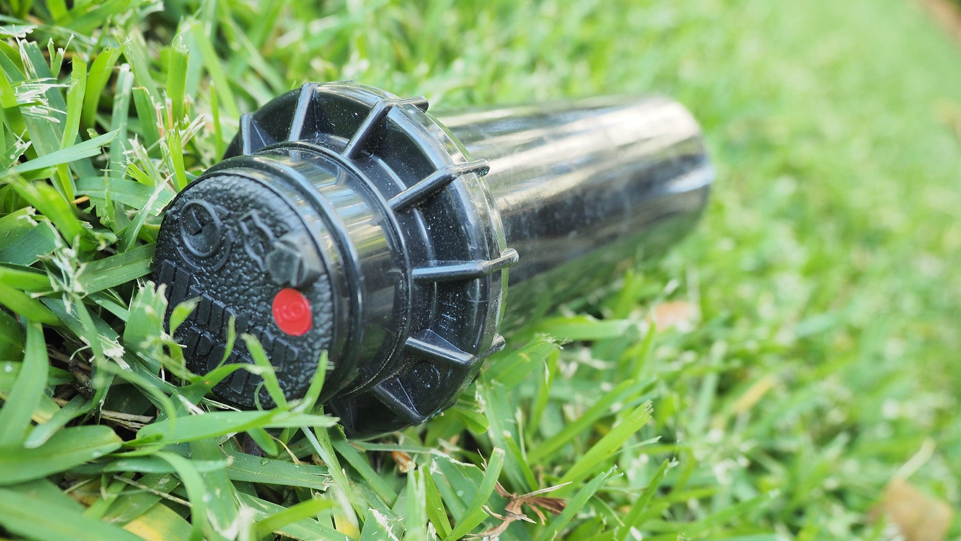 | Used for distribution of water in landscape and turf applications. |
|
Pop up turf rotor 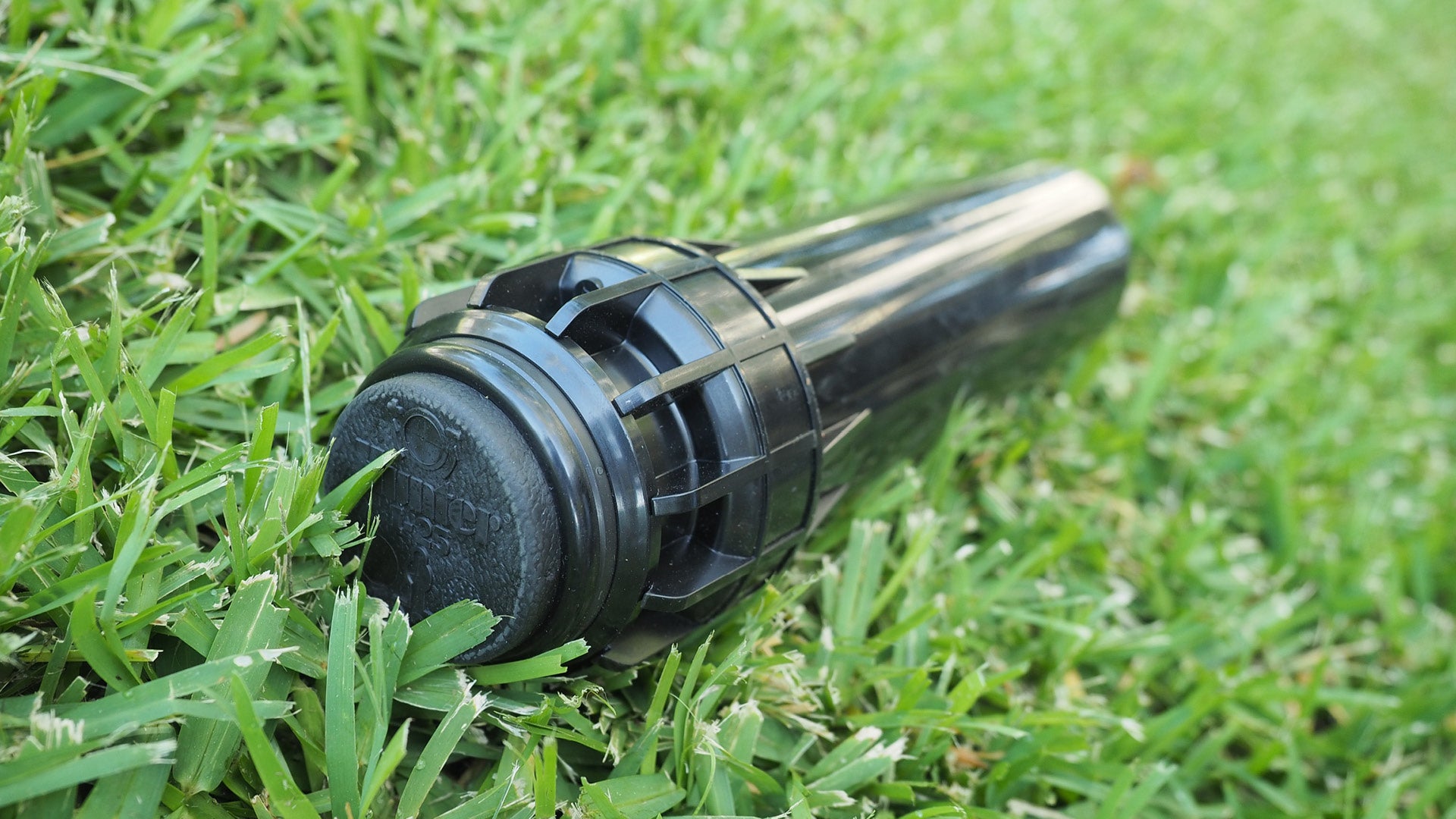 | Used for distribution of water in sports fields and large open space applications. |
|
Pop up shrub spray (300 mm)  |
|
|
MP (Matched Precipitation) spray 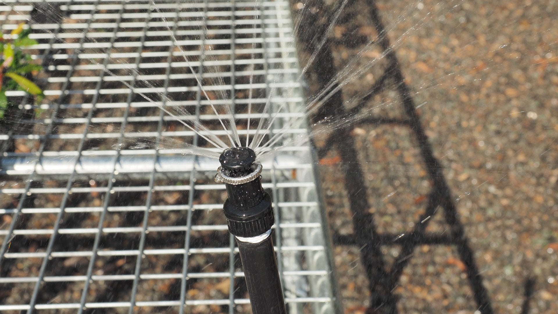 | Used for water distribution in turf and landscape situations. |
|
VANs (Variable Arc Nozzle) 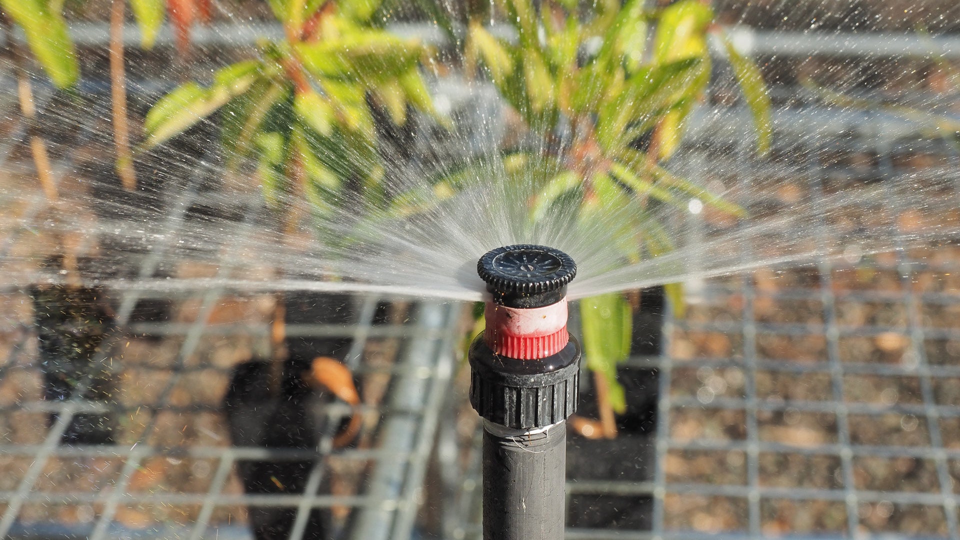 | Used for water distribution in turf and landscape situations. |
|
Drip irrigation tube (16 mm) 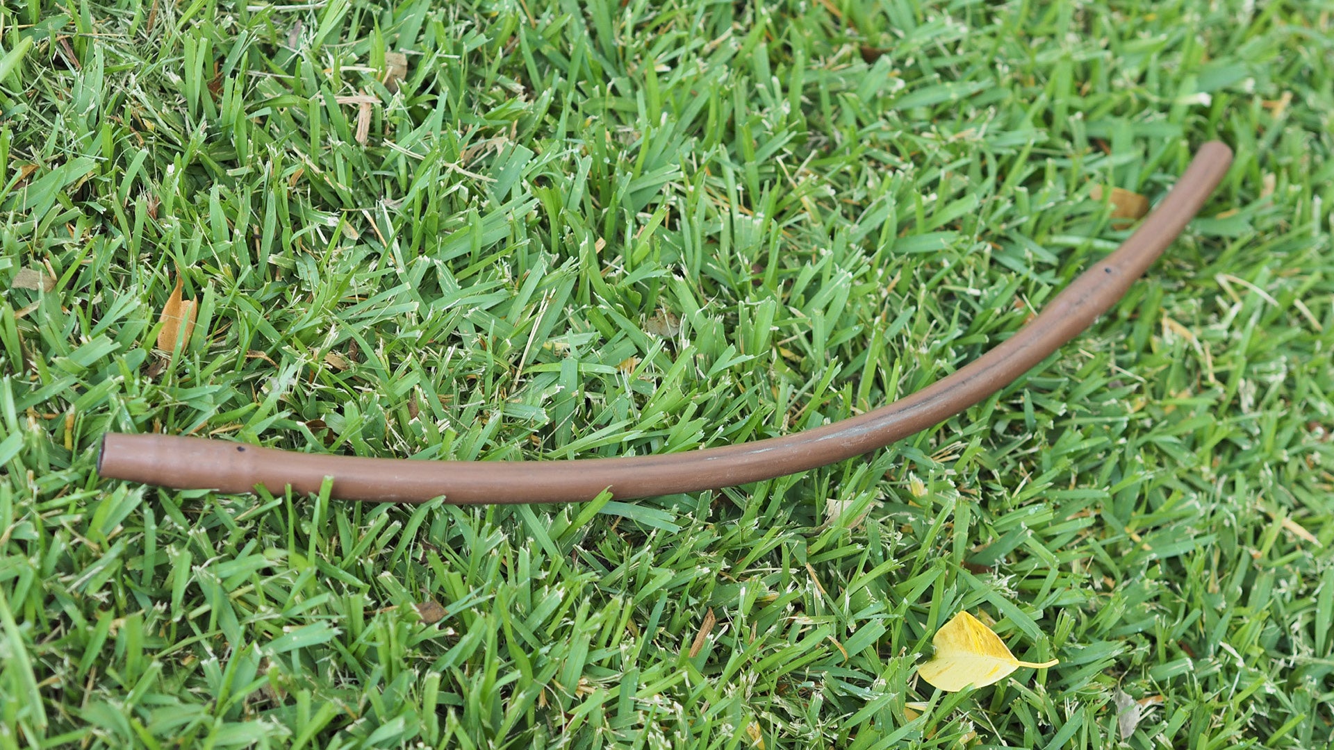 |
|
|
Fittings
Fittings are used to join or connect pipes, or to install componentry allowing measurement and control of the irrigation system.
See the following for further guidance:
- Figure 22: Typical fittings
- Table 7: Fittings types.
Threaded poly risers
A poly riser is used to compensate for height differences between lateral takeoff point and the required finished level of the emitter.
- Risers are available in different lengths to allow for differing trench depths and uneven landscape areas.
- Different thread patterns are available to suit particular situations and uses:
- Female to female
- Female to male
- Male to male.
Articulated poly risers (Swing arms)
Articulated risers, or swing arms are devices used to attach a rotor to a lateral line, and allows for height adjustment and suspension.
- With an articulated riser installed, the pop up sprinkler height can be easily adjusted to match the soil level.
- An articulated riser enables a level of suspension to allow for impact on the rotor caused by vehicular movement or foot traffic.
- Articulated risers are made of three 90° poly elbows and a poly riser connected to the lateral line via a tapping saddle.
- Articulated risers can be attached to a lateral poly line by means of female threaded elbows, female threaded tees or tapping saddles.
Poly elbows
Poly 90° elbows are used to provide 90° changes of direction on poly pipe.
Tapping saddles/bands
A tapping saddle or band is a device that attaches to the lateral line via series of bolts. It effectively clamps itself onto a lateral line and has a threaded socket that allows for another connection to be made at any designated point on the lateral line.
Figure 22: Typical fittings
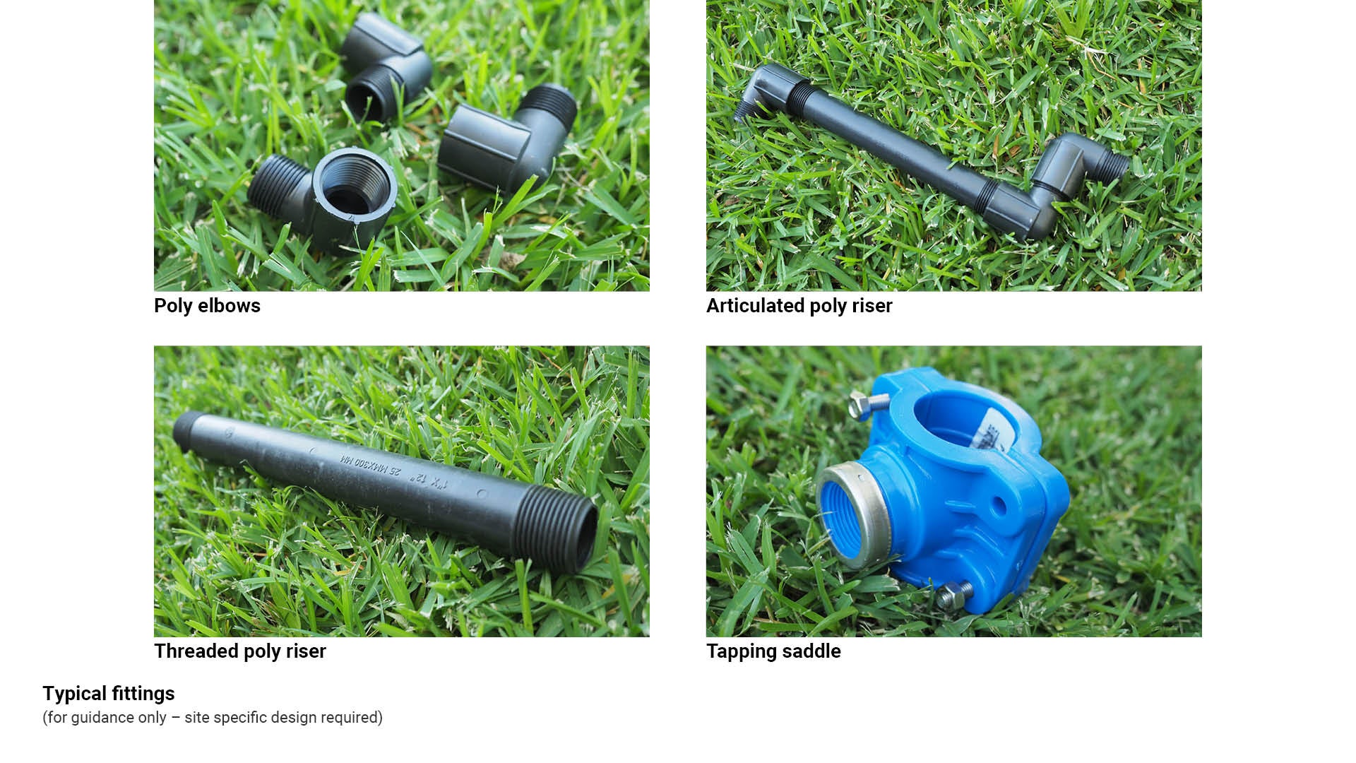
Table 7: Fittings types
Irrigation type | Recommended use/application | Key consideration |
Threaded poly risers 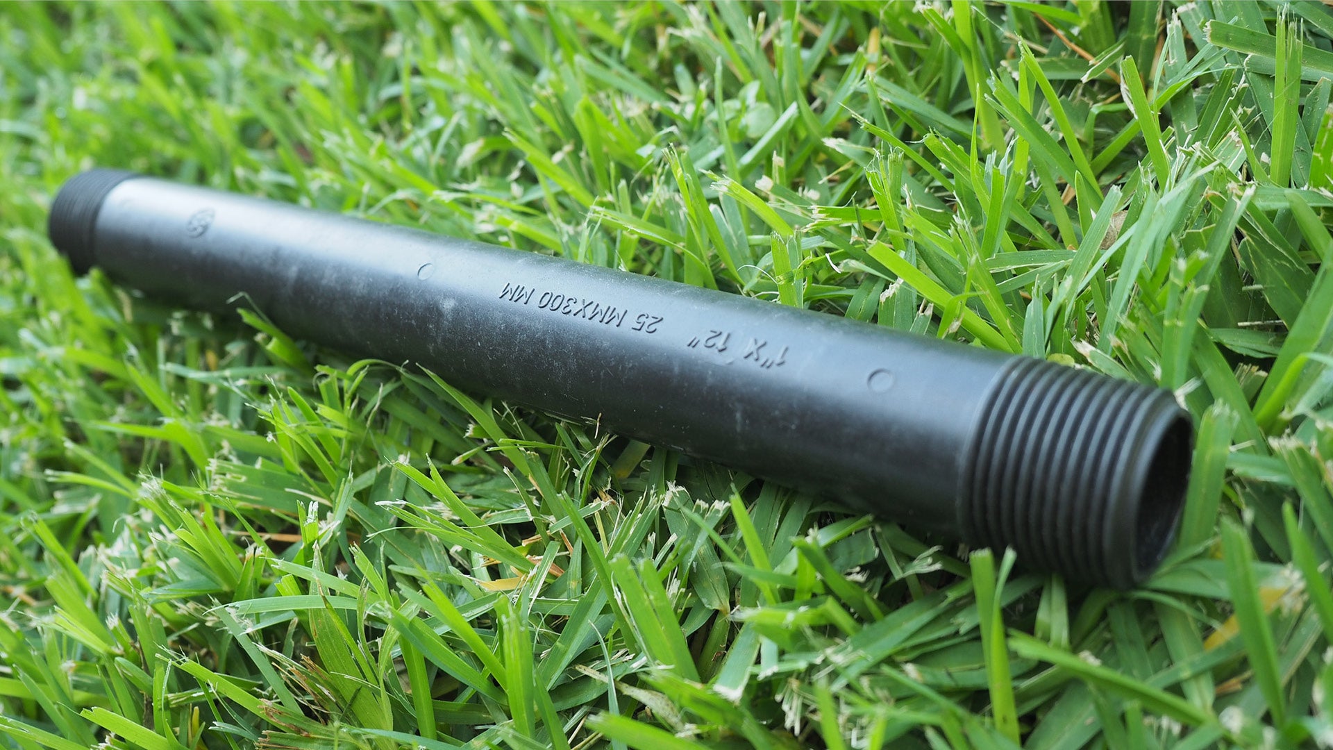 | Used to compensate for height differences between lateral takeoff point and required finished height of emitter. | Different lengths available to allow for different height requirements Available with differing thread patterns, e.g. female to female, female to male, male to male. |
Articulated riser components 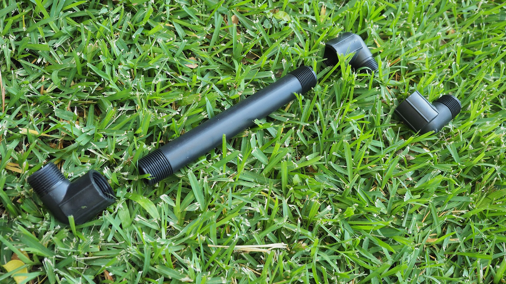 | Rotor attachment to a lateral line, to allow for adjustment and vertical movement. | Allows for vertical adjustment and suspension. |
25 mm LDPE (Low Density Polyethylene) director  | LDPE Connector into Solenoid valve. | |
Poly tapping saddle  | Allows connections to be made on a lateral line. | Stainless steel nuts and bolts. |
Poly electrofusion fitting 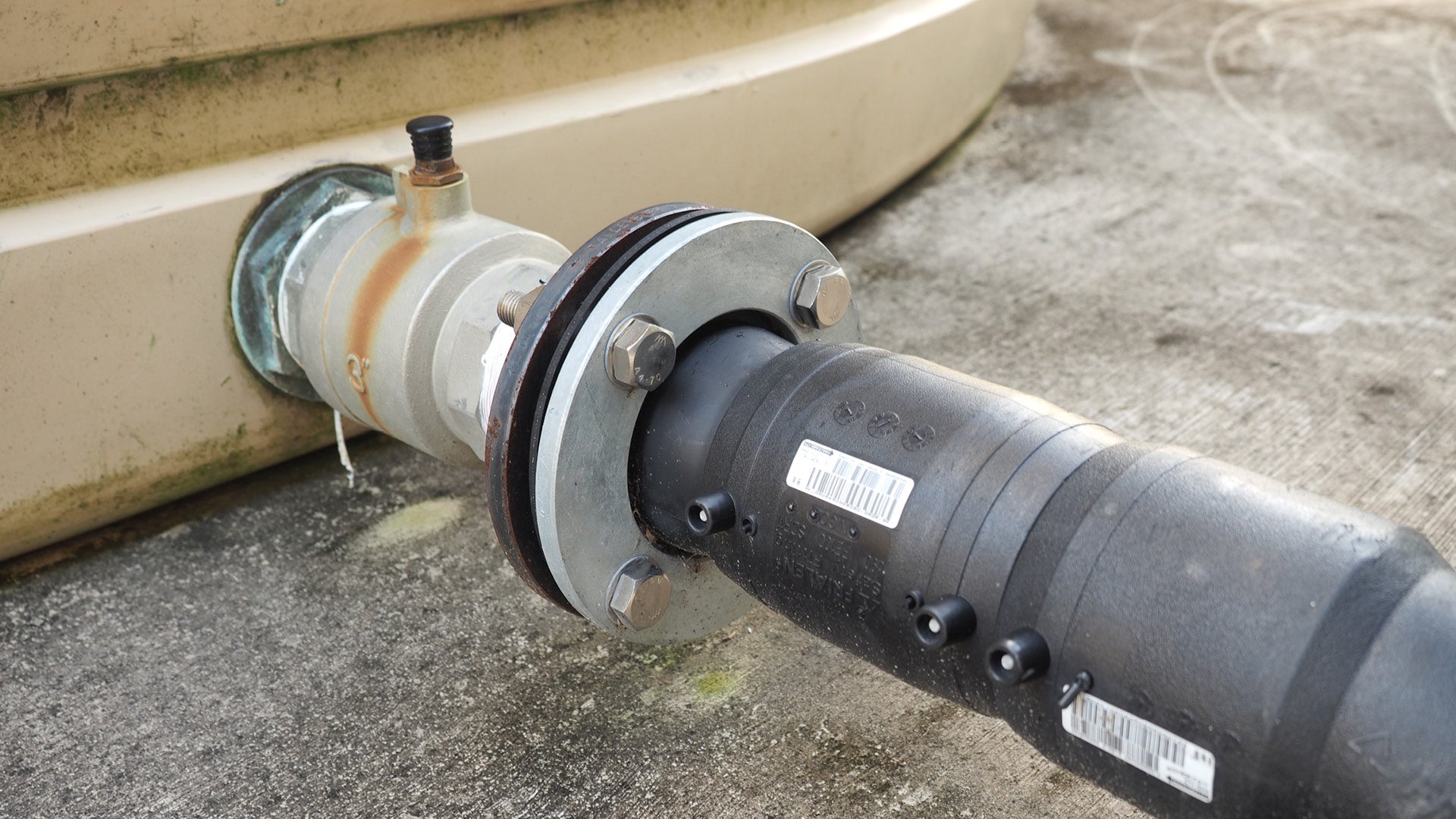 | Used for high pressure mainline joins and pump system manifold assembly. | All poly pipes are to be 90 mm or larger. |
Wire and cable
Low voltage cabling is to be used for irrigation installations, to connect electric solenoid valves to the irrigation controller.
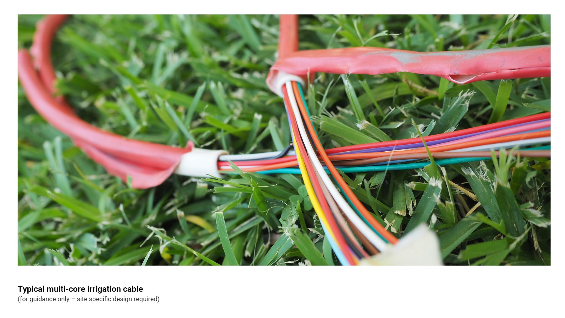
Multi-core irrigation cable
Multi-core irrigation cable is used to connect automatic irrigation controllers to electric solenoid valves.
- Multi-core irrigation cable can be buried underground and should be taped to the mainline when being installed to prevent damage from future excavation.
- Selection of the appropriate type of wire will be determined by the design requirements of the irrigation system and manufacturers recommendations.
See the following for further guidance:
- Figure 23: Typical multi-core irrigation cable
- Table 8: Wire and cable types.
Figure 23: Typical multi-core irrigation cable
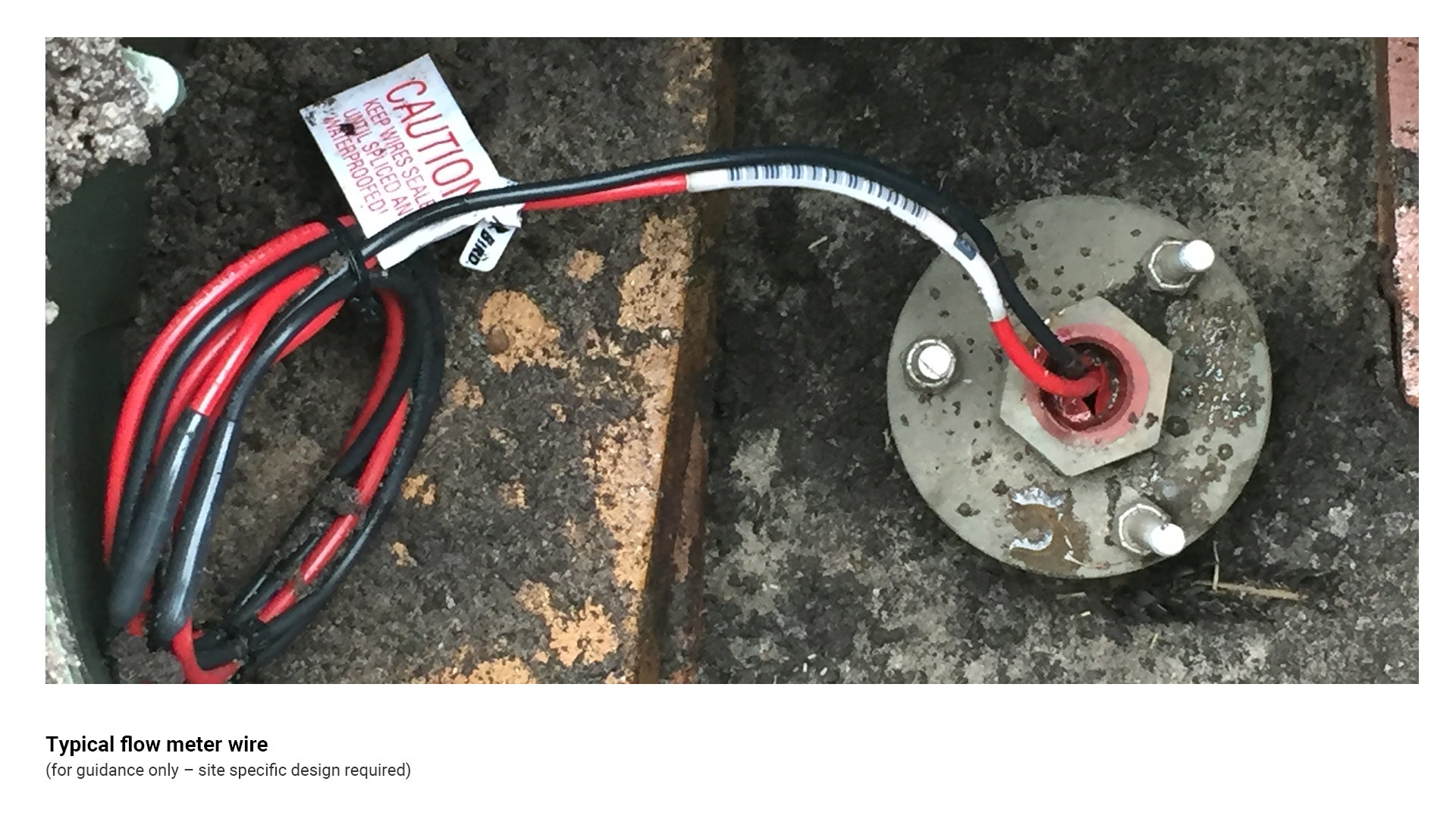
Flow meter wire
- Used to connect flow meter to irrigation controllers
- Two-wire cable is required.
- Shielded cable MUST be used between the controller and the meter. Earth from the shielded cable must be connected to earth in controller.
- Cable used must be dedicated to the flow meter, and should consist of two dedicated wires. This cable must not be shared with the common wire of the valves, solenoids or other sensors.
- Cable must not be installed in the same conduit or bunched with solenoid wires.
- Total cable length between the irrigation controller and the flow meter will determine the gauge of cable used.
See the following for further guidance:
- Figure 24: Typical flow meter wire
- Table 8: Wire and cable types.
Figure 24: Typical flow meter wire
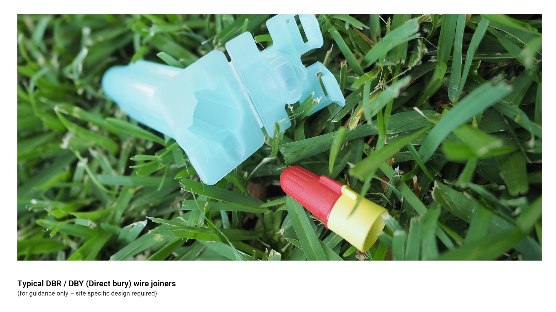
DBR/DBY (direct bury) wire joiners
Direct bury wire joiners are used to electrically connect two or more wires, providing a waterproof, non-conductive seal that can be installed directly in the ground.
Wire joiners connect and protect underground electrical connections for irrigation systems against corrosion and moisture.
- Contains twist-on wire connectors and gel filled tubes. Locking fingers in the tube ensure the connector stays in position.
See the following for further guidance:
- Figure 25: Typical DBR/DBY (Direct bury) wire joiners.
- Table 8: Wire and cable types.
Figure 25: Typical DBR/DBY (Direct bury) wire joiners
Heat shrink wire joiners
Insulated, water resistant wire joiners, heat shrinked around the wire join, consisting of a heat shrinkable cap for simple, fast sealing of multiple wire connections without the need for soldering.
Soldering and heat shrink joiners may be suitable where the joint is not subject to flooding at any time.
Heat shrink wire joiners:
- are made from polymer and heat-melt adhesive
- outer layer provides excellent insulation and is non-corrosive
- inner layer is air proof and waterproof
- best connected with a gas torch.
See the following for further guidance:
- Figure 26: Typical DBR/DBY (Direct bury) wire joiners
- Table 8: Wire and cable types.
Figure 26: Typical DBR/DBY (Direct bury) wire joiners
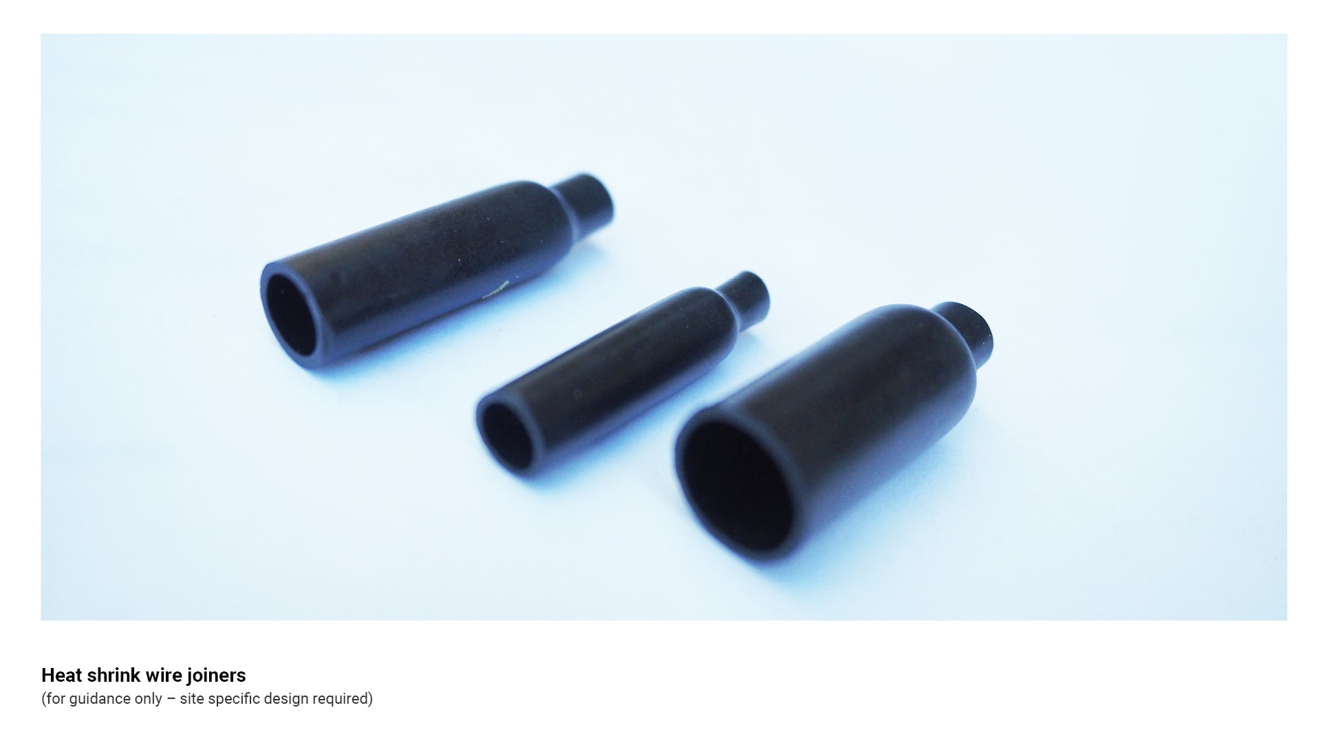
Table 8: Wire and cable types
Irrigation type | Recommended use/application | Key consideration |
Multi-core irrigation cable 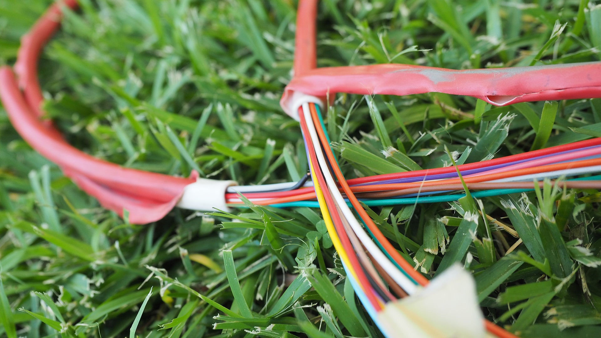 | Used to connect automatic irrigation controllers to electric solenoid valves. | Number of wires to be determined by solenoid valves in system. Cable diameter is to be determined by the distance from controller to solenoid valve. |
Flow meter wire 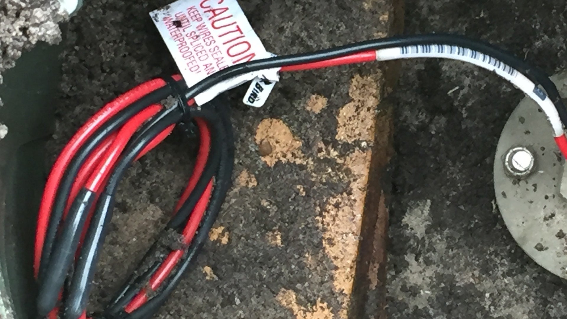 | Used to connect flow meter to irrigation controllers. |
|
DBR / DBY (Direct bury)wire joiner 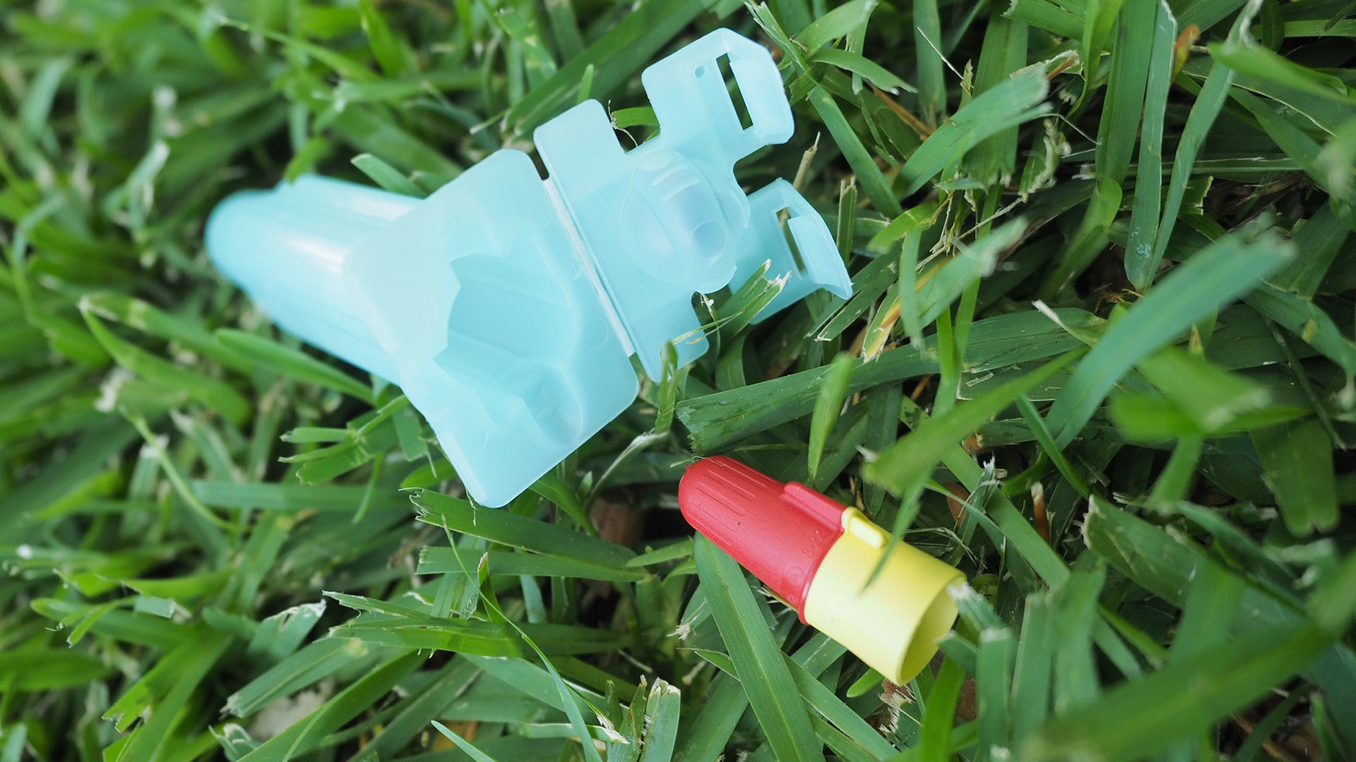 | Connects and protects underground electrical connections. |
|
Heat shrink wire joiners 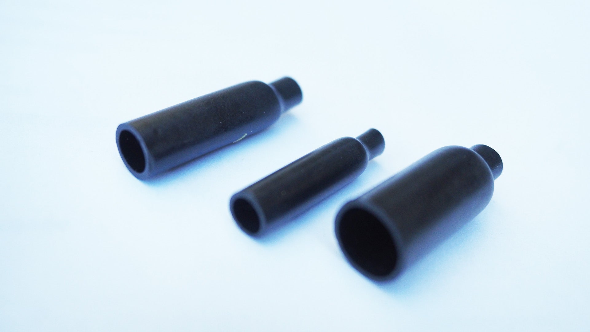 | Connects and protects underground electrical connections. |
|
This component is currently in development