Waterways (watercraft facilities)
Design
Requirements for the design, manufacture and installation of embellishments
Good design
See the following corporate documents to identify relevant project design requirements:
Sunshine Coast Planning Scheme regulates the way land, buildings and structures are used and developed on the Sunshine Coast.

Sunshine Coast Design contains 10 design principles that guide good project planning and design outcomes, that are appropriate for the Sunshine Coast.
The LIM provides further overarching design advice, refer:
- Introduction and Design Principles - e.g. sustainability, CPTED, accessibility
- Preliminaries - environmental management, tree sensitive design and site set up.
Embellishment requirements
- Universal access.
- Comfortable and suitable for the average person.
- See 'Positioning' and 'Equal access' sections for the corresponding LIM category.
- Made from materials that will be durable and can be suitably protected from exterior elements, such as salt spray and UV exposure.
- Robust and sturdy to withstand constant public use and be resistant to vandalism.
- Fixings are to be 316 marine grade stainless steel (unless otherwise stated).
- Tamper proof fixings should be used
- Graffiti protection coatings applied (where applicable)
- Fire retardant (where applicable).
- Warranties should be as listed below.
- Easily repairable or replaceable.
- Sourced locally and use standard fittings.
- Reputable suppliers should be used who keep a supply of stock parts on hand for the life of the product.
- Use sustainable materials, although sustainability needs to be considered over the lifetime of the embellishment.
- Install on paved, concrete or other hard surfaces (where applicable).
- Manufactured to engineering specifications (where applicable).
- See the 'Standards' section for the corresponding LIM category.
Warranty and asset life
Product/embellishment | Warranty (minimum) | Asset life (typical useful life) |
Boat ramps and stairs, floating walkways and pontoons – concrete | 50 years | 50 years 2 |
Boat ramps and stairs, floating walkways and pontoons – recycled plastic/composite fibre | 25 years | 25 years 2 |
Boat ramps and stairs, floating walkways and pontoons – stainless steel | 25 years | 25 years 2 |
Boat ramps and stairs, floating walkways and pontoons – hot dipped galvanised (after fabrication) | 25 years | 25 years 2 |
Boat ramps and stairs, floating walkways and pontoons – aluminium | 40 years | 40 years 3 |
Locks and weirs | 25 years | 60 years 2 |
Source 2: Sunshine Coast Council Asset Management Plan 2017/18-2022/23 – Parks and Gardens (figure based on current data, subject to change).
Source 3: Design Criteria for Floating Walkways and Pontoons, Transport and Main Roads, October 2015 (figure based on current data, subject to change).
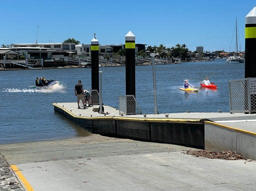
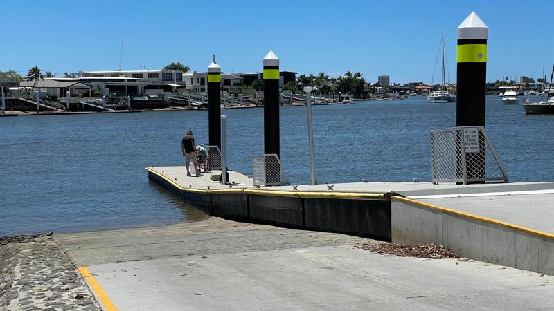
Watercraft facilities
Once the location of the watercraft facilities has been decided, based on the Environment and Liveability Strategy (ELS) and Recreation Parks Plan (RPP) guidance, consider the appropriate embellishment level to suit the selected site.
Overarching design considerations:
All open spaces should include universal access (e.g. provide accessible pedestrian ramps)
Locate new watercraft facilities near existing recreational facilities, such as public amenities, shelters, car parks and fish cleaning facilities.
Design of watercraft facilities
Marine structures and their use
There is no legal limit to where non-motorised craft can launch.
See Table 1: Uses - marine structures for further guidance.
Table 1: Uses - marine structures
Marine facility | Intended use (examples only) |
Boat ramp |
|
Jetties/floating walkways/pontoons |
|
Portage and access |
|
Canoe/kayak trails |
|
Temporary/permanent/vehicle access |
|
Locks and weirs |
|
Equal access paths |
|
Equal access paths |
|
Boat ramp (motorised and or non-motorised watercraft)
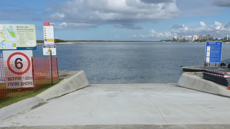
Boat ramps provide access for launching and retrieval of trail-able vessels into a waterway. Standard boat ramp design and construction of in-water components is provided by Department of Transport and Main Roads (DTMR).
- Council may project manage the construction of the in-water components of a boat ramp.
- Council provides the land-based components and manages the facility when completed.
DTMR Design Manual applies to the design of boat ramps for the launch and retrieval of recreational trailer boats where the gross combined vehicle mass (GCVM) including trailer with vessel and tow vehicle, does not exceed 8,000 kg.
Boat ramps within the Sunshine Coast Council are sign limited to a GCVM of 5,000 kg.
- Design boat ramps for safety considering:
- Pedestrian movements
- Operational movement of vehicles on the ramp
- Vessels near the ramp
- Future sea level rise caused by global warming.
DTMR design manual provides a set of standard drawings for use in new and upgraded boat ramps.
Note: The Department of Transport and Main Roads (DMTR) works in partnership with local government and port/water authorities to provide new and improved recreational boating facilities throughout Queensland. Under these long standing arrangements, Transport and Main Roads builds the in-water components of a facility and councils and port/water authorities provide the land-based components, and then manage the whole facility when completed.
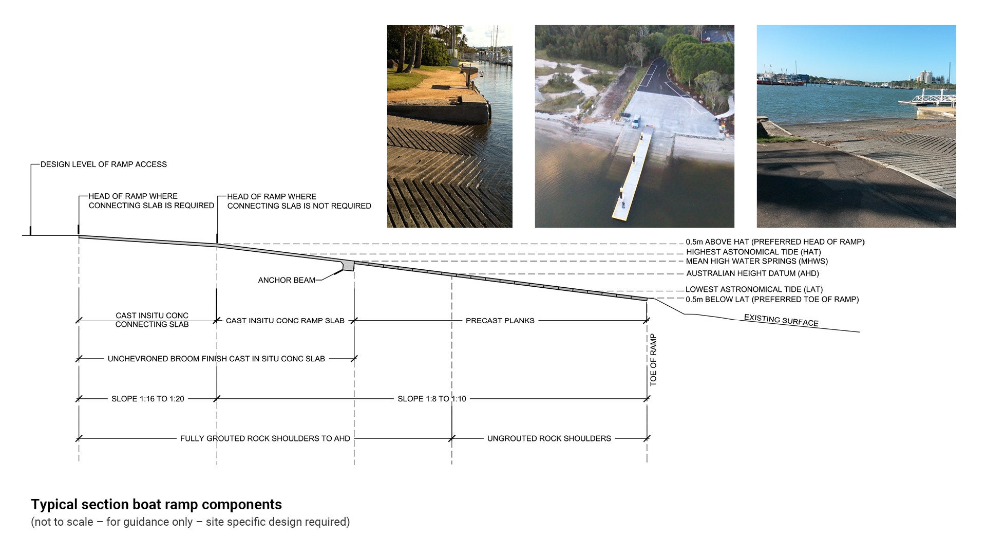
Ramp components
Boat ramps (minimum width 4.0 m) comprise the anchor beam or start of the connecting slab, the batters of the ramp and the toe of the ramp. Typical boat ramp components, such as, the number of planks recommended, are detailed and specified in DTMR standard drawings and include:
- Crushed rock core or base.
- Grouted shoulders and shoulder batters.
- Crushed rock shoulders.
- Cast in-situ anchor beam or connecting slab with anchor beam.
- Geotextile and geogrid for separation of base materials and containment of the core.
Rock base, shoulders and batters
- Depth of footings below existing surface are site specific dependant upon factors such as lowest astronomical tide (LAT) and geotechnical site constraints.
- Batters to be 400 mm thick and grouted.
- Select durable stone. Seek professional advice when selecting stone type. Consider the effects salt water may have on some stone types, such as disintegration.
- Shoulder ramps in cut have a drainage channel 10 mm clearance below the invert of the plank or ramp drainage groove to ensure free drainage of the ramp surface.
- Shoulder ramps on fill to have stone pitched surface 30 mm below the ramp surface so that drainage grooves are free draining.
- Stone faces are to be essentially flat. Avoid protrusions to reduce potential hull damage and trip hazards to pedestrians.
Concrete anchor beams
- Resist permanent loads and flood, wave action and operational loads.
- Full length lanes should use an anchor beam which may either be a discrete component or integrated with a ramp or connecting slab.
Ramp planks
- Ramp plank numbers are guided by a DTMR demand study.
- Planks are constructed from pre-cast concrete.
- Principal plank type is 4.0 m wide for a single lane ramp.
- Multi lane ramp may be required where there is demand.
See Figure 1: Typical section boat ramp components for further guidance:
Figure 1: Typical section boat ramp components
Associated embellishments
Incorporate new watercraft facilities into existing compatible recreational parks where possible.
The location of facilities should be alongside existing recreation parks or boat ramps to allow for shared use of existing facilities.
- Associated boat ramp embellishments may include:
- Car parks/roads. See Department of Transport and Main Roads (DTMR) Guidelines and standard drawings.
- Signs and line marking
- Lighting and water supply
- Waste facilities
- Fish cleaning tables
- Fishing line disposal units
- Toilets
- Shelters
- Shade trees and shade structures.
- Watercraft transferred to boat ramps by vehicle require longer parking spaces to accommodate a vehicle and boat trailer. See DTMR Guidelines.
- Rigging/de-rigging bays are required for motorised and non-motorised watercraft.
- Waiting bays are required at high volume sites.
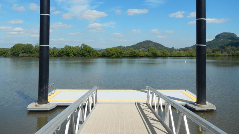
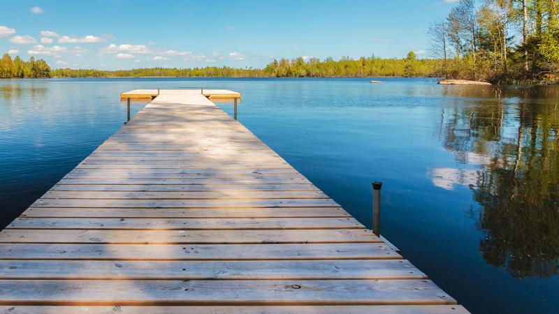
Jetties, floating walkways, pontoons (non-motorised watercraft/pedestrian use)
Landings can provide short-term shore access for deep-drought vessels for the transfer of passengers and provisions or for short-term shore excursions.
Recreational boating infrastructure is to be designed in accordance with Department of Transport and Main Roads (DTMR) requirements.
DTMR design manual applies to jetties and floating structures which are intended to support launching and retrieval of recreational vehicles.
Floating structures include:
- Modular floating walkways for pedestrian use, may be constructed adjacent to a shoreline.
- Pontoons with gangways are usually located adjacent to boat ramps.
- Pontoons must display manufacturer’s name and serial number.
- Pontoons are to be designed to sit on the canal, river or seabed at low tide without incurring any structural damage.
- Intended use for non-motorised craft only when freeboard is below 150 mm.
- Incorporate ability to install disability compliant access points with this infrastructure.
- Both motorised and non-motorised water craft may moor at a pontoon.
The design generally extends from the connection with landside facilities to the flotation module(s) including:
- Piles and pile restraint system.
- Flotation modules including deck furniture
- Abutment, connections with the flotation modules and interaction between the abutment and floating walkway support lane (floating walkways only).
- Abutment, and fixed and hinged sections of the gangway (pontoons only).
- DTMR design manual provides a list of standard drawings for use in new jetties and floating structures.
See Figure 3: Typical section pontoon with gangway.
Components
Typical jetty and floating structure components as detailed and specified in DTMR standard drawings include:
Jetty
A horizontal decked pedestrian walkway on piered or piled footings which provides pedestrian access from the shore to a waterway. Boats can dock or be moored to a jetty.
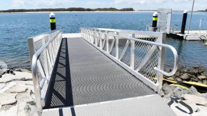
Gangway
A raised platform or walkway providing pedestrian access between a walkway or shore and a floating structure or vessel. Minimum clear width of 1.8 m.
Floating walkway
A linear pontoon system constructed from multiple hinged flotation modules. May be supported on a boat ramp lane at low tides. Minimum clear width of 1.8 m.
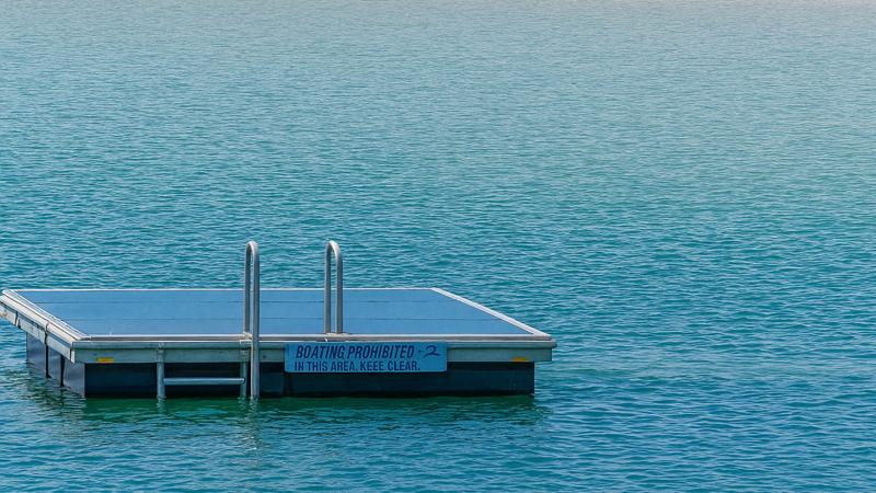
Pontoon
A floating platform used for access to the water or a vessel. Flotation modules are to be secured to each other and the abutment by 316 stainless steel wire rope and shackle anchor system to restraint piles.
Equal access, may incorporate facilities to support disability compliant launch points.
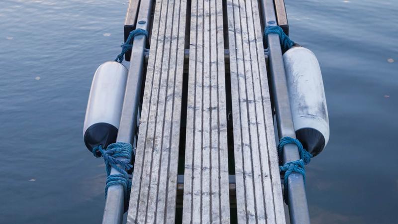
Fenders
Absorb energy and may be constructed from moulded HDPE or rubber to protect vehicles against damage during berthing.
- Council does not prefer the use of rubber tyres as fenders due to concerns about the impacts of petrochemical and heavy metal leachate.
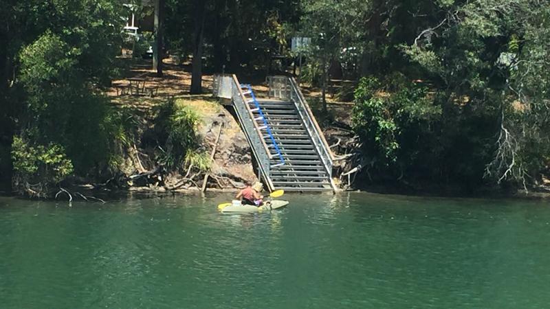
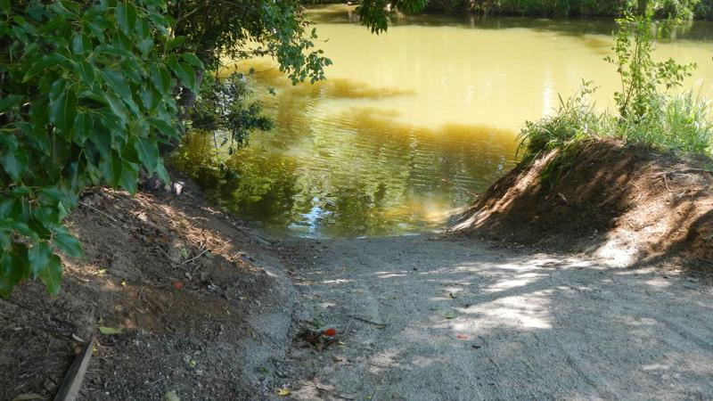
Portage and access (non-motorised watercraft and pedestrians)
Portage or portaging is the practice of carrying watercraft across land, between two bodies of water. A place where this occurs is called a portage.
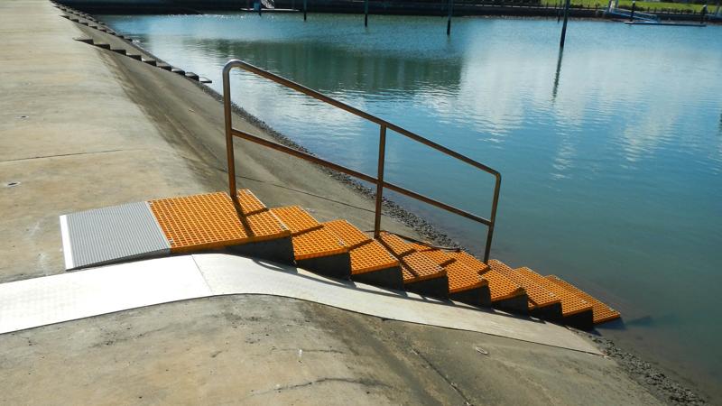
Kayak and canoe access from land to water is to be provided via stairs and ramps.
A skid, slide or mat is an inclined ramp used for the manual launching of small water craft from land to water.
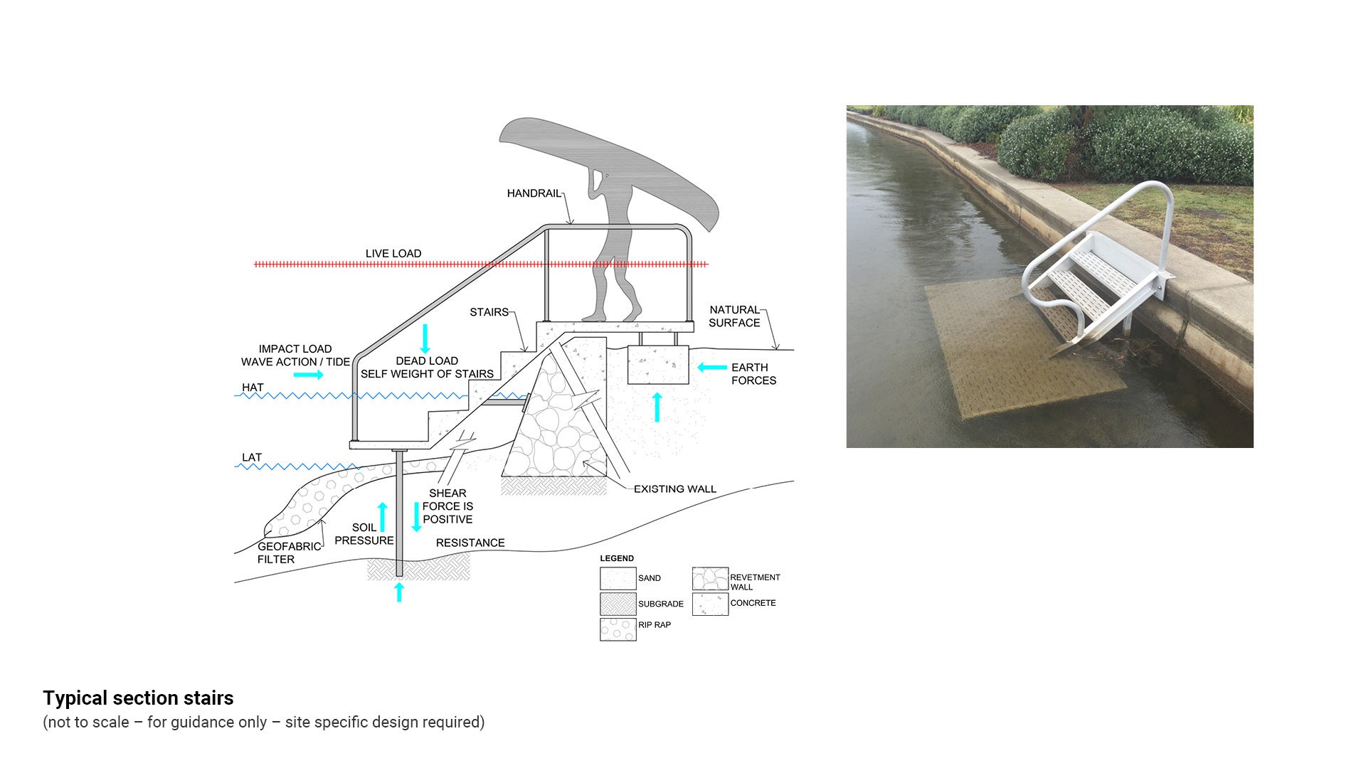
Access stairs design
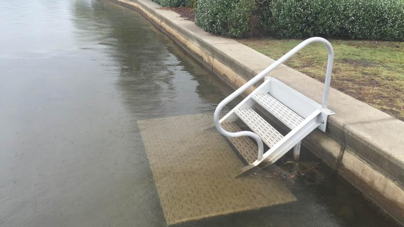
Consider the following when designing new or retro-fit stair systems for canoe, kayak and non-powered watercraft:
- When retro-fitting a stair access system to an existing wall, stairs vertical loading must be independent of the marine structure (weir or revetment wall).
- Determine structural soundness of the revetment wall for intermediate support if required.
- Consider all connections, especially for relocatable structures.
- Determine existing ground conditions such as rock, clay, or sand.
- The vertical force (weight of stairs acting downwards) should not exceed the bearing capacity of the soil.
- Scour protection such as rip rap may be required at the foot of the stairs.
- Install geofabric material to ensure separation of rip rap and underlying material.
- Consider stairs loading:
- Dead load (DL) to AS 1170.1:1989 Dead and Live loads and combinations (SAA Loading Code)
- Live load (LL) to AS 1170.1:1989 Impact load (IL) such as boats and kayaks
- Types of support for independent foundations include:
- pre-cast concrete
- driven piles
- timber or sheet piles.
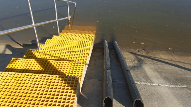
- Stair treads and handrails are to be constructed from an appropriate material to minimise marine build up.
- High profile sites such as lakes and canals may require a platform at the bottom of the stairs.
- An anti-fouling material is required for construction of stair treads, platforms/sunken landings to prevent accumulation of marine organisms.
- Consider a range of watercraft and longer kayaks when designing an access system.
- Consider requirements for all abilities and age groups including seniors when designing an access system. Such as:
- Handrail design (height and diameter).
- TGSIs (where appropriate)
- Luminance contrast stair nosing treatment.
For permit application drawing requirements refer to Department of Environment and Heritage Protection (DEHP) guideline Constructing Tidal Works.
See the following for further guidance:
- Figure 4: Typical section stairs
- Table 3: Materials for water access facilities.
- LIM Walls.
Figure 4: Typical section stairs
Slides, skids and ties
A skid is an inclined ramp used for the manual launching of small, light craft.
- Where appropriate include a slide/mat mechanism such as soft rubber (or other material) adjacent to stairs, to prevent watercraft damage when hauled across it.
- A weatherproof corrosion resistant pulley system such as galvanised cord/wire may be attached to stairs at the water line to allow watercraft to be secured for boarding or disembarking.
- Watercraft wash down facilities such as a shower with a hose or a stand. are desirable in close proximity to a portage system.
- Recommended design is two posts with a crossbeam cradle covered in rubber or artificial turf. Users can place their craft on the cradle to be washed down.
Stairs with slide
Stairs with mat
Stairs with skid
Canoe and kayak trails
Canoe and kayak trails allow individuals to experience a way to connect to the natural environment.
When designing canoe launch locations, consider the use of natural features such as deposition zones and rock outcrops, before installing formal infrastructure.
- Canoes and other non-motorised watercraft should be launched and landed from designated public or identified access sites (put-ins).
- Use of shoreline areas other than designated locations can cause degradation and bank erosion.
- Ensure that main entry point launching sites are located near to embellishments (where possible) such as:
- Car parking
- Waste bins
- Public amenities
- Showers or wash down facilities (to minimise the spread of aquatic weeds)
- Shelters
- Picnic and barbecue facilities.
- Weirs are to include canoe and kayak access arrangements.
Signs
Signage should clearly show all required information to inform people where a river trail is intended for non-motorised watercraft such as canoes and kayaks.
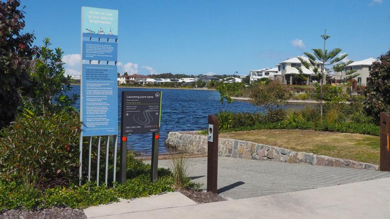
- Install an Activity entry sign for river trails at the beginning of a canoe trail. This sign should provide information about facilities and details such as paddling times.
- Install environmental signs to provide information about caring for rainforest, protected areas and environmentally sensitive areas.
- Install numbered signing (Activity entry sign – River trails) along the banks of a canoe trail to assist with paddler orientation and planning. This sign type should also include the current location and forward and backward destinations.
- All signs should be constructed from robust materials such as marine grade aluminium and should include anti-graffiti coating.
See the LIM Signage - Activity entry signs for further guidance.
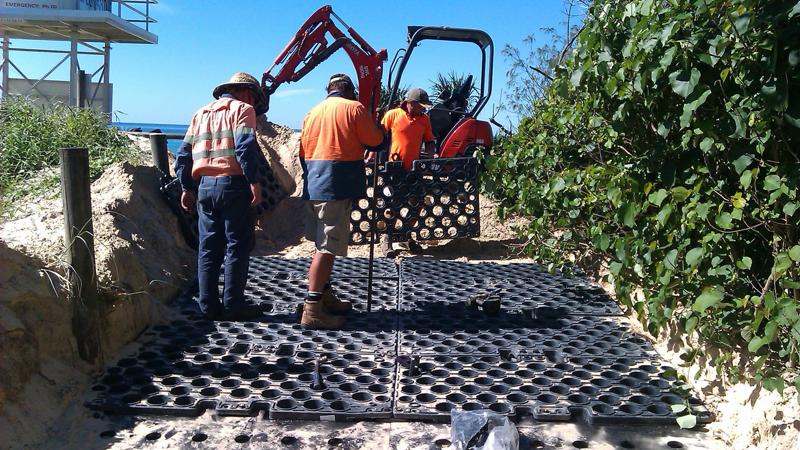
Vehicle access (temporary and permanent)
Permanent vehicle access onto beach foreshores may be required for emergency services vehicles such as Surf Life Saving Australia, Queensland Ambulance Services and State Emergency Services.
Recycled plastic, composite fibre material and rubber matting can be installed wherever vehicle access is required and the natural surface does not support vehicle loads.
Temporary vehicle access may be required during:
- Construction projects for materials/plant delivery.
- In emergency disaster situations such as vehicle access for accident, flood, fire and oil spill clean up.
- For major beach event temporary facility set-up and removal.
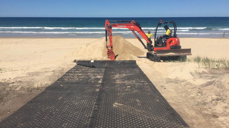
Vehicle access systems
TrackPad (or equivalent)
- Replas (or equivalent) TrackPad system comprises moulded polyethylene (PE) plastic pads.
- Modular vehicular panels may be installed in ground for temporary or permanent vehicle beach access.
- The surface is able to be backfilled with local material to preserve a natural aesthetic.
Enviro Belt 40 (or equivalent)
- Rubber Enviro Belt 40 (or equivalent) is recycled mine conveyor belt with 40 mm holes punched at 100 mm centres
- Enviro Belt can be installed to provide temporary or permanent vehicle access.
- The surface is able to be backfilled with local material to preserve a natural aesthetic.
Locks and weirs
Weir
A weir is a horizontal barrier across a waterway designed to alter the flow characteristics. Water pools behind the weir and may be allowed to flow steadily over the top. A weir can act as a flood bypass channel.
- Weirs provide the opportunity for recreational activities including:
- Fishing
- Canoeing
- Kayaking
- Boating
- Other water sports
- Walking.
- Weirs may include kayak and canoe access points where feasible. The use of portage pontoons should be limited.
Lock
A lock is a mechanical fixed chamber in which the water level can be varied. Locks are used to provide watercraft access from tidal waterways into lake and canal systems, having different water levels.
- The function of the mechanical lock and weir is to maintain a constant water level in a canal system or lake, independent of the high and low tides which occur in a tidal waterway.
- Marine vessels are able to travel between river and canal systems and tidal waterways.
- Access can be provided via an electronic key/card reader near lock gates.
- Access keys/cards are available on payment of fees and charges.
- Painted, galvanised coating to fabricated handrails and miscellaneous steelwork is to be in accordance with Sunshine Coast Planning Scheme – for development works – Table SC.14.8.
The very nature of lock and weir systems on natural waterways is highly sensitive with regards to hydrodynamic and ecological impacts and should be assessed and guided by relevant experts accordingly.
Engage a suitably qualifies Registered Professional Engineer in Queensland (RPEQ) to undertake design of locks and weirs.
Note: It is recommended that assessment by an Aquatic Ecologist (or relevant expert) is undertaken prior to commencing lock and weir investigations.
This component is currently in development