Ramps and stairs
Design
Requirements for the design, manufacture and installation of embellishments
Good design
See the following corporate documents to identify relevant project design requirements:
Sunshine Coast Planning Scheme regulates the way land, buildings and structures are used and developed on the Sunshine Coast.

Sunshine Coast Design contains 10 design principles that guide good project planning and design outcomes, that are appropriate for the Sunshine Coast.
The LIM provides further overarching design advice, refer:
- Introduction and Design Principles - e.g. sustainability, CPTED, accessibility
- Preliminaries - environmental management, tree sensitive design and site set up.
Embellishment requirements
- Universal access.
- Comfortable and suitable for the average person.
- See 'Positioning' and 'Equal access' sections for the corresponding LIM category.
- Made from materials that will be durable and can be suitably protected from exterior elements, such as salt spray and UV exposure.
- Robust and sturdy to withstand constant public use and be resistant to vandalism.
- Fixings are to be 316 marine grade stainless steel (unless otherwise stated).
- Tamper proof fixings should be used
- Graffiti protection coatings applied (where applicable)
- Fire retardant (where applicable).
- Warranties should be as listed below.
- Easily repairable or replaceable.
- Sourced locally and use standard fittings.
- Reputable suppliers should be used who keep a supply of stock parts on hand for the life of the product.
- Use sustainable materials, although sustainability needs to be considered over the lifetime of the embellishment.
- Install on paved, concrete or other hard surfaces (where applicable).
- Manufactured to engineering specifications (where applicable).
- See the 'Standards' section for the corresponding LIM category.
Warranty and asset life
Product/embellishment | Warranty (minimum) | Asset life (typical useful life) |
Concrete ramps and stairs | 10 years | 50 years 2 |
Timber ramps and stairs | 15-25 years | 25 years 2 |
Recycled plastic/composite ramps and stairs | 10 years | Not available |
Stainless steel ramps and stairs | 10 years | 50 years 2 |
Aluminium ramps and stairs | 10 years | 40 years 2 |
Source 2: Sunshine Coast Council Asset Management Plan 2017/18-2022/23 – Parks and Gardens (figure based on current data, subject to change).
Ramps and stairs
Once the location of the ramps and stairs has been decided, based on the Environment and Liveability Strategy (ELS) and Recreation Parks Plan (RPP) guidance, consider the appropriate embellishment level to suit the selected site.
Overarching design considerations:
All open spaces should include universal access (e.g. provide accessible access by providing ramps in addition to stair options).
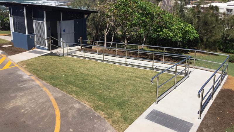
Ramps
- Ramps provide pedestrian access to a site where there is a difference in levels (natural or artificial) between two physical planes.
- Ramps include handrail, barrier and kerb to assist pedestrian and cyclist access.
- Ramps may also be used to bridge over existing tree roots to reduce potential damage to tree and open space natural areas.
Stairs
- Stairs or flights of stairs are a series of steps leading from one physical plane to another. Stairs include handrail, barrier and kerb to assist pedestrian access. Where stairs are installed, include a ramp for equal access (where possible).
Landings
- Level landings are required at the top and bottom of stairs and ramps and at intermediate intervals to allow rest opportunities, particularly for older people and people with disabilities.
- Tactiles/stair nosings
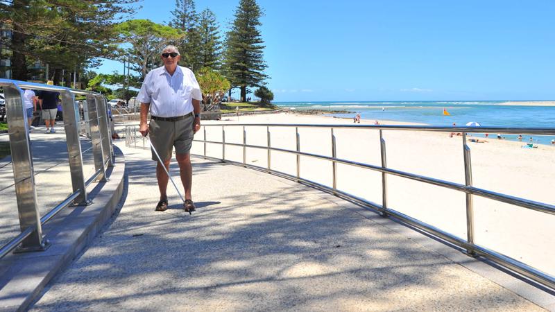
- The addition of coloured stair nosings and tactile ground surface indicators at the top and bottom of stairs and ramps, aids in the movement of people with low vision.
Design of ramps and stairs
A ramp is an inclined surface on a continuous accessible path of travel (CAPT) between two landings with a gradient steeper than 1 in 20 but not steeper than 1 in 14.
Stairs provide access where a path of travel passes through vertical changes from one level to another level.
- Ramps and stairs may form part of a continuous path of travel designed in accordance with AS 1428.1:2009 Design for access and mobility – General requirements for access – new building work.
- Consider all pedestrian and cyclist user group needs when selecting handrails and barrier fences.
- Install kerb rails or kerbs (concrete up stand) to prevent wheeled mobility devices and pram wheels from becoming trapped.
- Install handrails to both sides of ramps and stairs to assist vision impaired people (VIPs), injured people, older people and people with a disability.
- Handrails are needed on both sides of ramps and stairs to accommodate people who are left handed and people who are right handed.
- Install barrier (balustrade) to prevent the risk of falls.
- Install ‘rub rails’ (where required) to protect cyclists from balusters, when a ramp is used by cyclists (refer to Cycling Aspects of Austroads Guides).
- A ramped deck (timber, concrete, metals, recycled material or composite material) may be required to bridge over surface root systems (depending upon the tree species). Existing trees can suffer direct construction injury through loss of structural and feeder roots or indirect construction injury via reduced access of roots to water, oxygen, nutrients and growing space. A qualified arborist can provide specific advice for trees under threat of damage.
- Level landings minimum 1.2 m long are required at the top and bottom of stairs where there is no change in direction.
- Where there is a change in stairs direction (up to 90 degrees), distance between handrails at an intermediate landing must be minimum 1.2 m long.
- For ramp grades of 1:14, landings are required at maximum intervals of 9.0 m.
- For ramp grades steeper than 1:20, landings are required at maximum intervals of 15 m.
- A ramp cannot be used to connect one level to another where the vertical rise is greater than 3.6 m. This is to ensure the ramp does not cause undue fatigue.
Ramps
Ramps contain an inclined surface on a path of travel between two landings at different levels
- Access to facilities where a ‘path of travel’ passes through vertical changes from one level to another level.
- Designers should select a ramp rather than stairs where only one is possible, to provide access for the widest range of abilities.
- A maximum grade of 1:14 for ramps exceeding 1.9 m in length.
- A level landing (rest area) preceding the ramp and a level landing to finish the ramp.
- Level landings at intervals based upon the ramp grade and length.
- Consideration for all pedestrian modes such as cyclists, wheelchairs, mobility scooters and parents with prams when designing ramp widths, particularly in high use areas.
- Handrails and kerbs are required on both sides of the ramp to assist left handed and right handed people (excepting where a building or wall abuts one side of the ramp).
- For multiple ramps, install hazard TGSI on intermediate landings if there is a break in one or both of the handrails.
- Paint, tape or integrated high visibility colour treatment to handrail ends to improve visibility.
- A risk assessment is to be carried out for handrails that are near any road edge, where there is potential for it to become a ‘spearing hazard’ in the event of an accident.
See the following for further guidance:
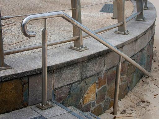
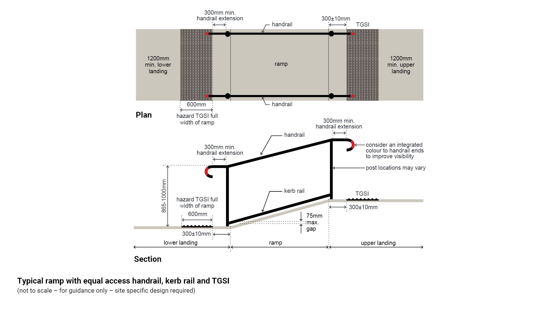
- Figure 1: Typical ramp with equal access handrail, kerb rail and TGSI.
- LIM Handrail and balustrades.
Note 1: If a pathway is shallower than 1:20, it is a walkway and does not require handrails. Exceptions occur at locations with an adverse fall height. See AS 2156.2 for fall height assessment.
Note 2: Install hazard TGSI to the top and bottom of ramps for a single ramp and where there are multiple ramps with continuous handrail.
Install hazard TGSI to intermediate landings if there is a break in one or more handrails.
Figure 1: Typical ramp with equal access handrail, kerb rail and TGSI
Ramp design and construction
Ramps are to be designed and constructed in accordance with:
- AS 1428.1:2009 Design for access and mobility – General requirements for access – new building works.
- AS 2156.1:2001 Walking Tracks – Classification and signage.
- Austroads Guide to Road Design Part 6: Roadside Design, Safety and Barriers (Risk assessment).
Equal access ramps
AS 1428.1:2009 Design for access and mobility – General requirements for access – new building works:
- Ramps on a continuous accessible path of travel (CAPT) must include:
- a grade between 1:20 and 1:14.
- tolerance for error where the ramp is shallower than 1:14 is 3%.
- ramp grades of 1:14, landings at 9.0 m intervals.
- ramp grades steeper than 1:20, landings at 15 m intervals.
- level landings top and bottom of ramp TGSI to landings top and bottom of a ramp.
- landings at all changes of direction.
- landings to be minimum 1200 mm long.
- landings by linear interpolation for grades between 1:20 and 1:14.
- where scooters are used and the ramp change of direction exceeds 60 degrees, the landing length should be a minimum of 3.0 m.
- landings to be minimum 1500 mm long where there is a change in ramp direction.
- handrails to both sides of the ramp.
- on a series of ramps where the handrail is not continuous, include TGSI to top and bottom of intermediate landings.
- ramps and intermediate landings must have kerb or kerb rails on both sides.
- On a kerb ramp
- a maximum grade of 1:8.
- maximum rise 190 mm.
- maximum length 1520 mm.
- The only instances where TGSI would not used on kerb ramps:
- where the gradient is between 1:8 and 1:8.5.
- the distance between the building or property line is less than 3.0 m.
- the kerb ramp is aligned with the building line and the direction of travel across the carriageway.
- On a step ramp
- a maximum grade of 1:10
- maximum rise of 190 mm
- maximum length 1900 mm.
- On a threshold ramp
- a maximum grade of 1:8
- maximum rise of 35 mm
- maximum length 280 mm.
See LIM Ramps and stairs – Positioning ramps for further guidance on kerb ramps, step ramps and threshold ramps.
Recreation paths/trails ramps
AS 2156.1:2001 Walking Tracks – Classification and signage
- Steps are allowed only with alternate ramp access (where possible).
Ramps adjacent to roadways
Austroads Guide to Road Design Part 6: Roadside Design, Safety and Barriers
- A risk assessment is to be carried out for handrails that are near any road edge, where there is potential for it to become a ‘spearing hazard’ in the event of an accident.
Stairs
Stairs provide access where a path of travel passes through vertical changes from one level to another level.
Stairs require:
- A level landing area minimum 1200 mm long at the stairs start and finish. Minimum intermediate landings 1200 mm.
- Rises and goings of a uniform dimension (BCA maximum tolerance 5.0 mm in rise and going through any flight of stairs). Non-uniform stairs can cause people to stumble and fall.
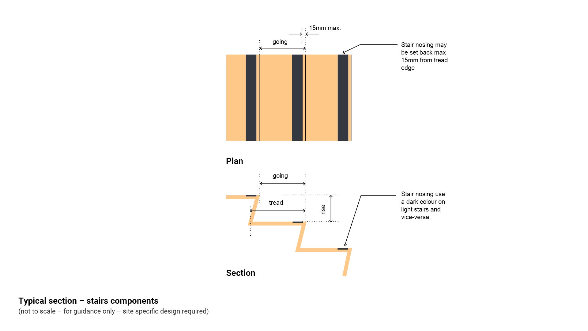
- Minimum going is to be 300 mm and the preferred going is 350 mm. At 350 mm trips and falls through overstepping virtually disappear.
- Treads constructed from a slip resistant material.
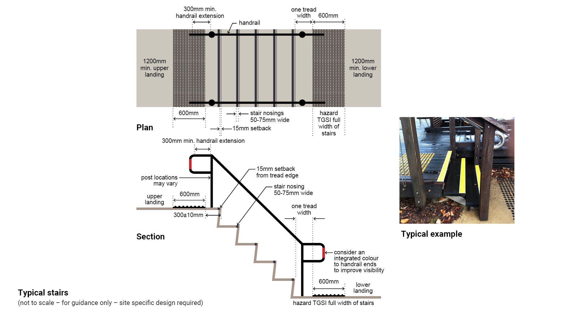
- Treads which have a luminance contrast strip, minimum 50 mm and maximum 75 mm deep with a maximum 10 mm exposed end at the face of the riser, across the full width of the stairs.
- Luminance strip may be set back a maximum 15 mm from the front of the stair tread.
- Handrails both sides to assist left handed and right handed people.
- Install hazard TGSI on top and bottom landings.
- Balustrade where required.
- Paint, tape or integrated high visibility colour treatment to handrail ends to improve visibility.
- A risk assessment is to be carried out for handrails that are near any road edge, where there is potential for it to become a ‘spearing hazard’ in the event of a accident.
Note: Install hazard TGSI to the top and bottom of stairs for a single flight of stairs, and where there are multiple flights of stairs with continuous handrail.
Install hazard TGSI to intermediate landings if there is a break in one or more handrails.
Flights of stairs
A flight or group of multiple stairs is to include the following additional elements:
- Maximum of 18 rises, minimum 2 rises in a straight flight of stairs.
- More than one straight flight of 18 rises must be connected by a level landing.
- Install hazard TGSI on intermediate landings if there is a break in one or both of the handrails.
See the following for further guidance:
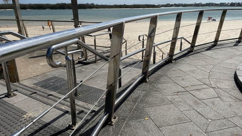
- Figure 2: Typical stairs
- LIM Tactiles
- LIM Handrails and balustrades.
Figure 2: Typical stairs
Stairs design and construction
Stairs are to be designed and constructed in accordance with:
- AS 1428.1:2009 Design for access and mobility – General requirements for access – new building works.
- AS 1657.1:2013 Fixed platforms, walkways, stairways and ladders (inspection/maintenance stairs).
- AS 2156.2:2001 Walking tracks – Infrastructure design (recreational trails).
- Austroads Guide to Road Design Part 6: Roadside Design, Safety and Barriers (Risk assessment)
Equal access stairs
AS 1428.1:2009 Design for access and mobility – General requirements for access – new building works.
- Level landings to top and bottom of stairs
- landings within stairs are to be minimum 1200 mm long.
- landings to be minimum 1200 mm long where there is a change in stairs direction.
- Handrails to both sides of the stairs
- Treads to be slip resistant material
- Stairs are to have opaque risers.
- Luminance contrast nosing strip for the full width of the stairs, 50 mm - 75 mm on the tread and 10 mm maximum on the exposed face of nosing strip.
- The luminance contrast nosing strip may be set back a maximum of 15 mm from the nose of the tread.
- Set stairs back a minimum of 900 mm from a building boundary so that handrails and TGSI do not protrude into a perpendicular path of travel.
Include supplementary ramped access when installing stairs (where possible)
Walking frame stairs
Configuration of specialist steps for users with walking frames (may not comply with normal requirements of regulatory authorities):
- Goings between 575 mm and 600 mm.
- Rises between 95 mm and 105 mm.
Maintenance stairs
AS 1657:2013 Fixed platforms, walkways, stairways and ladders – Design, construction and installation for use by operating/inspection/maintenance personnel.
- A slope between 26.5° and 45°.
- A minimum of three rises.
- Uniform rises between 130 mm and 225 mm.
- Goings between 215 mm, and 355 mm.
- A tread overlap minimum 10 mm, maximum 30 mm.
- Level landings at points of access to the stairway.
- Handrails both sides of the stairs for stairs over 1.0 m wide.
- Treads to be slip resistant material.
- The combination of twice the riser plus the going (2R + G) must be not less than 540 mm, and not greater than 700 mm.
Recreation paths/trails stairs
AS 2156.2:2001 Walking tracks – Infrastructure design
- Path classification is contained in AS 2156.1:2001 Walking tracks: Classification and signage.
- Class 2 tracks are to have 18 risers maximum
- Class 3 tracks are to have 36 risers maximum between landings.
- Minimum landing length 900 mm.
See Figure 3: Typical section – stairs components.
Stairs adjacent to roadways
Austroads Guide to Road Design Part 6: Roadside Design, Safety and Barriers
- A risk assessment is to be carried out for handrails that are near any road edge, where there is potential for it to become a ‘spearing hazard’ in the event of a accident.
Figure 3: Typical section – stairs components
Beach stairs
Stairs are typically installed to provide safe access to the beach. They help prevent erosion, protect the dunal environment and make a trip to the beach more comfortable and accessible for visitors.
All materials used must be suitable for a marine environment and should have the following durability:
- require minimum ongoing maintenance.
- 50 year design life for structural elements.
- 20-25 years for timber portions of the build, such as stair treads.
Materials for consideration
- Marine grade aluminium – (preferred, because it is much lighter, easier to repair and construct and safer to install).
- Grade 316 SS
- Timber
- Preferred red and grey ironbark, turpentine or spotted gum would also be suitable.
- All edges to all have round overs and minimise use of checkouts, cuts and penetrations.
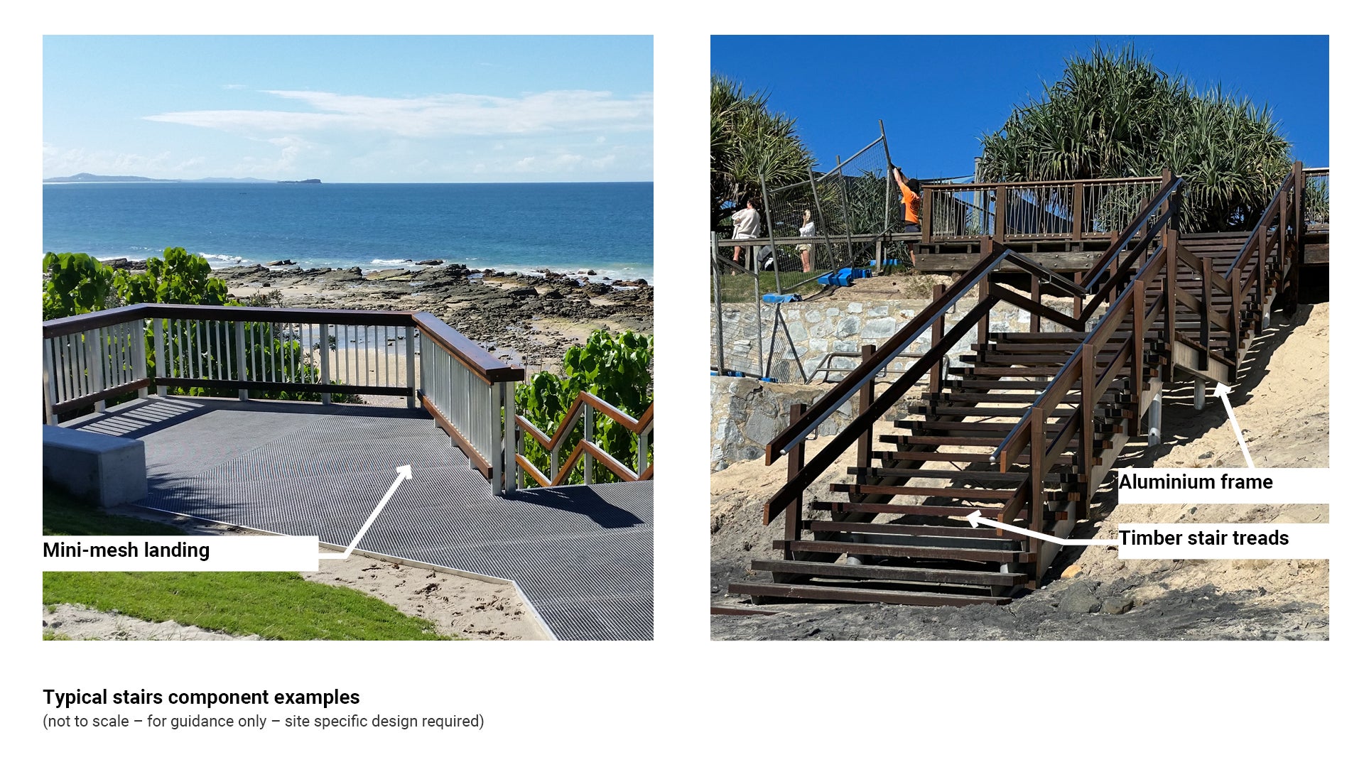
- Timber treads – typically 75 mm thick provides increased longevity. H4 to H5 treated. (Smaller tread widths also prevent ‘cupping’ of a large 300-350 mm wide board). Decking to be installed heart down. Asset custodian to determine if anti-cupping grooves are required (can be cut at the sawmill).
- Timber balustrade – H3 or H4 treated.
- Composite/GFRP (Glass Fibre Reinforced Polymer) structural members not preferred.
- Composite members (or equivalent) to be approved by the superintendent.
- When designing beach stairs consider the following:
- Frame – marine grade aluminium 6082, piles to be marine grade aluminium or bored concrete piers to a suitable depth for scour.
- Handrails – Grade 316 SS.
- Fasteners – Grade 316 SS. Provide nylon separation washers where dissimilar metals are used.
- Landings and walkways – typically 38 mm thick mini or micro mesh fitted to engineers specifications.
- Desirable widths – typically relaxed stairs are preferred in public spaces for best comfort levels, however when it comes to beach stairs, it is important to use as little footprint area as possible to reduce the dunal area impact and below ground interference. Using a relaxed stair design may result in metres of extra footprint - not desired. Use:
- 1650 mm clear width between balustrades
- tread rise between 150-175 mm
- tread going 280-350 mm
- minimesh landings/walkways to match factory sheets to reduce wastage.
- Treatments for timber
- Walkway surfaces such as treads and deckboards require a min 2 coats of Lanotec, Tanacoat or Cutek (or equivalent).
- Touch points such as balustrades, seats and lean rails – min 2 coats of Ultradeck (or equivalent).
- Other systems such as Cutek CD50 (or equivalent) to be assessed on a case by case basis if proposed.
See the following for further guidance:
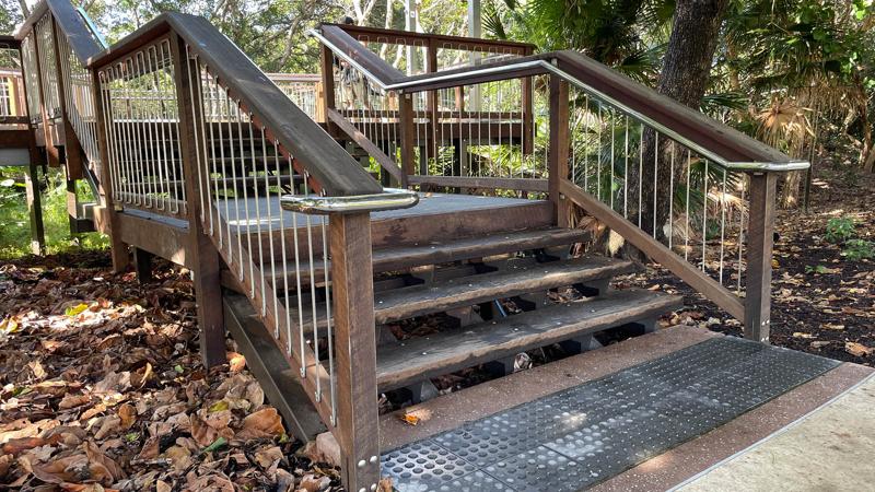
- Figure 4: Typical stairs component examples.
- LIM Beach infrastructure for other beach access options.
- LIM Handrails and balustrades.
Other considerations
Aluminium, GFRP (or equivalent), stair treads are suitable for particular applications, such as where treads may be submerged in water frequently. Aluminium treads are most appropriate in marine environments. Aluminium treads are appropriate for marine environments. Timber treads in marine environments have the potential to grow mould, creating a slippery surface.
Mini-mesh aluminium used for stair treads are not preferred for the following reasons:
- Can be complicated e.g. additional stringers are required for mini-mesh treads.
- The appearance can be unappealing and the finish is not as user friendly as timber e.g. if you stub your toe on a timber tread it is much softer.
- Timber is a durable and aesthetically pleasing material and with an appropriate maintenance regime, can achieve a long design life.
Figure 4: Typical stairs component examples
This component is currently in development