Ramps and stairs
Positioning - ramps
Best practice guidance for the placement and arrangement of embellishments
Ramps for purpose-built applications
Ramps for purpose-built applications are designed to provide equal access to buildings, car park spaces and across roads. Purpose-built applications include kerb ramps, step ramps and threshold ramps.
Inserted kerb ramp
Provides access to dedicated equal access car park spaces or across roads and contains the following elements:
- Maximum rise of 190 mm
- Maximum length of 1.52 m
- Maximum gradient of 1:8
- Recessed into a path of travel and a kerb
- Can be inserted into the path of travel
- Select plain coloured concrete ramp and wings as standard on council controlled roads. A colour treatment may be used when luminance contrast cannot be achieved.
See the following for further guidance:
- Figure 5: Typical compliant inserted kerb ramp
- Figure 6: Typical plan – inserted kerb ramp at parallel equal access parking
- Figure 7: Typical plan – inserted off road kerb ramp at 90° equal access parking
- LIM Bollards
- LIM Signage.
Note: Tactiles are not required where a kerb ramp is compliant with AS 1428.1:2009 Design for access and mobility – General requirements for access – new building works.
Figure 5: Typical compliant inserted kerb ramp
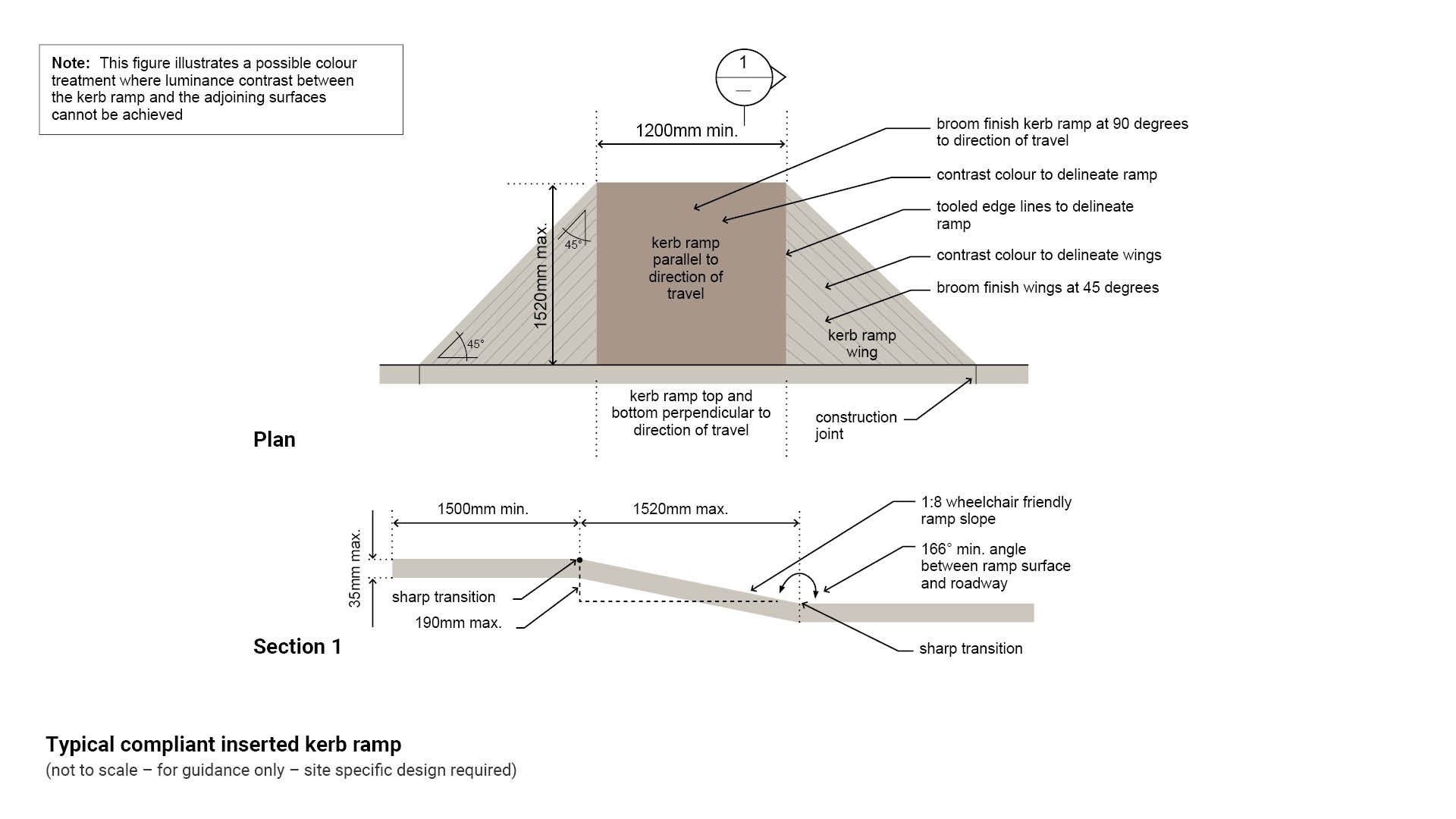
Figure 6: Typical plan – inserted kerb ramp at parallel equal access parking
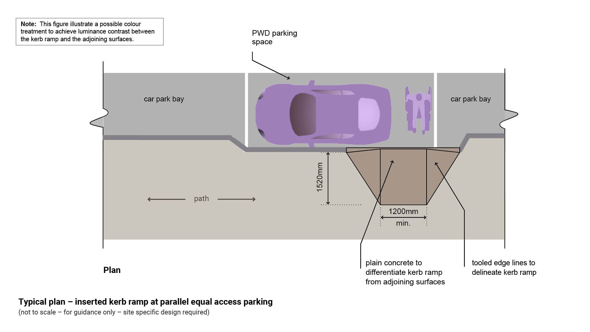
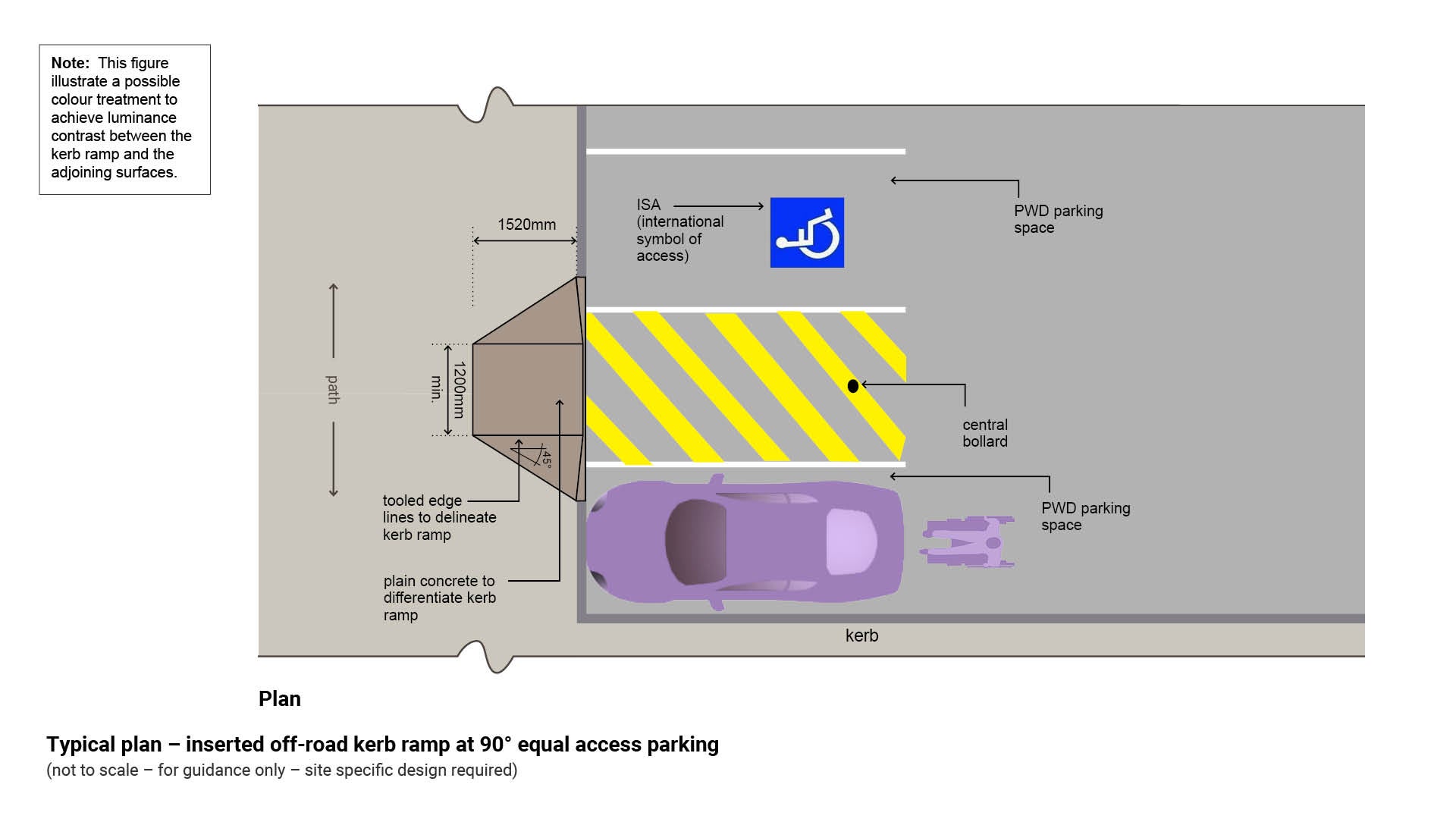
Figure 7: Typical plan – inserted off road kerb ramp at 90° equal access parking
Attached kerb ramp
Provides access to dedicated equal access car park spaces or across roads and contains the following elements:
- Maximum rise of 190mm
- Maximum length of 1.52m
- Maximum gradient of 1:8
- Attached onto a path of travel and a kerb
- Attached onto the path of travel.
- Select plain coloured concrete ramp and wings as standard on council controlled roads. A colour treatment may be used when luminance contrast cannot be achieved.
See the following for further guidance:
- Figure 8: Typical plan – attached kerb ramp
- LIM Bollards.
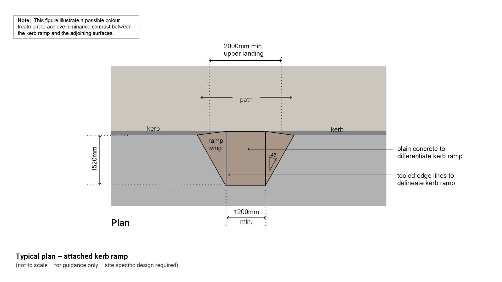
Figure 8: Typical plan – attached kerb ramp
Note: Tactiles are not required where a kerb ramp is compliant with AS 1428.1:2009 Design for access and mobility – General requirements for access – new building works.
Inserted kerb ramps at a road crossing
Provide access onto a road for pedestrians crossing over to the opposite side of the road. Kerb ramps must contain the following elements:
- Maximum rise of 190 mm
- Maximum length of 1.52 m
- Maximum gradient of 1:8
- May be inserted into a path of travel and a kerb.
- May be attached onto a path of travel and a kerb.
- Ramps are to be aligned parallel to the pedestrian direction of travel. Ramps on both sides of a road shall be aligned with one another and the direction of travel.
- Select plain coloured concrete ramp and wings as standard on council controlled roads. A colour treatment may be used when luminance contrast cannot be achieved.
- Where a kerb ramp is not directly opposite another kerb ramp, it is non-compliant with AS 1428.1:2009 Design for access and mobility - General requirements for access - new building work.
- Where TGSI are required, install at 90° to the path of travel required to cross from one side of the road to the other.
- A person who is blind or has low vision may not be able to proceed in a straight line beyond a 3.0 m distance. All additional clues will assist in maintaining the safe direction of travel.
See the following for further guidance:
- Figure 9: Typical plan – compliant kerb ramps at a road crossing
- Standard Drawing RS-092 Installation of TGSI’s on ramped kerb crossings.
- Standard Drawing RS-093 Installation of TGSI’s on ramped kerb crossings application examples.
Note: Tactiles are not required where a kerb ramp is compliant with AS 1428.1:2009 Design for access and mobility – General requirements for access – new building works.
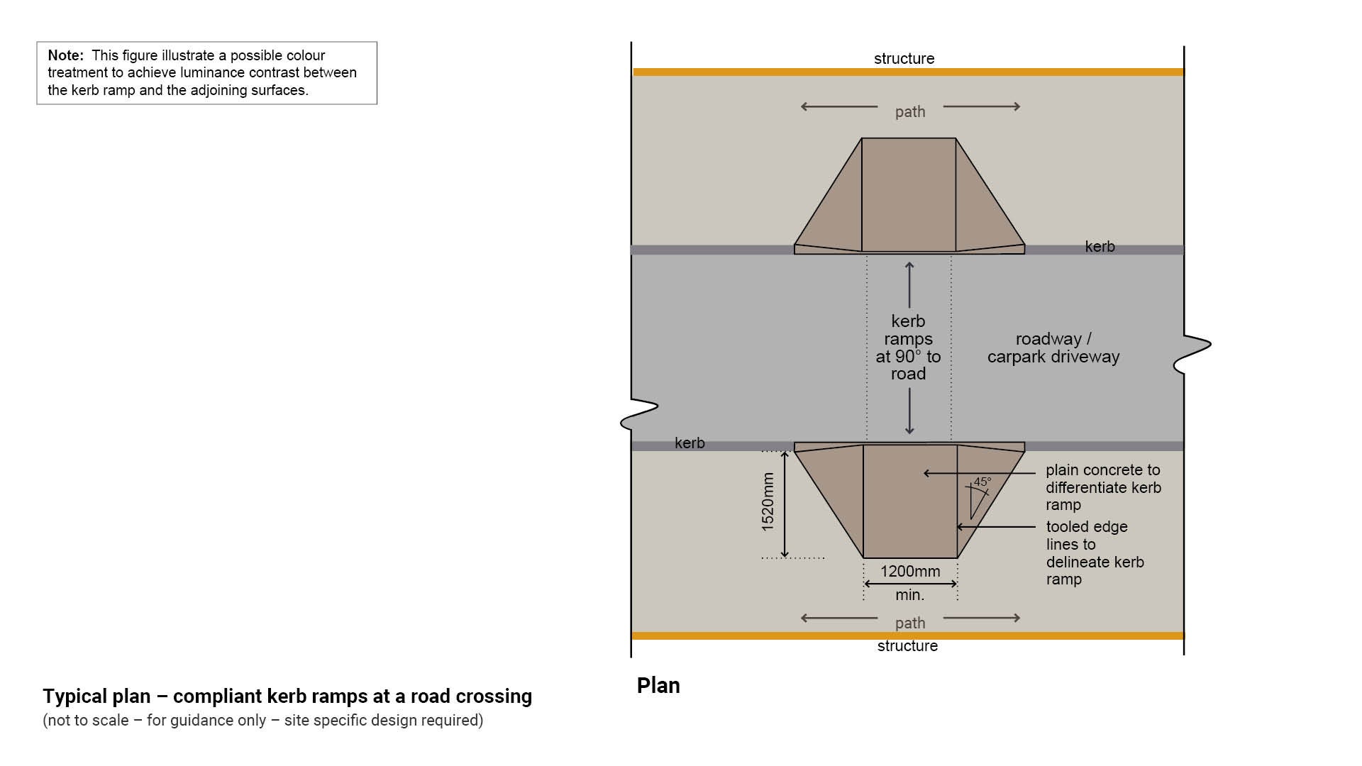
Figure 9: Typical plan – compliant kerb ramps at a road crossing
Threshold ramps
Provide access at a building doorway and contain the following elements:
- Maximum rise of 35 mm
- Maximum length of 280 mm
- Maximum gradient of 1:8
- Maximum 20 mm from the door leaf that it serves
- Edges of the ramp may be tapered or splayed at a minimum 45° where the ramp does not abut against a wall.
See Figure 10: Typical section – threshold ramp at a door.
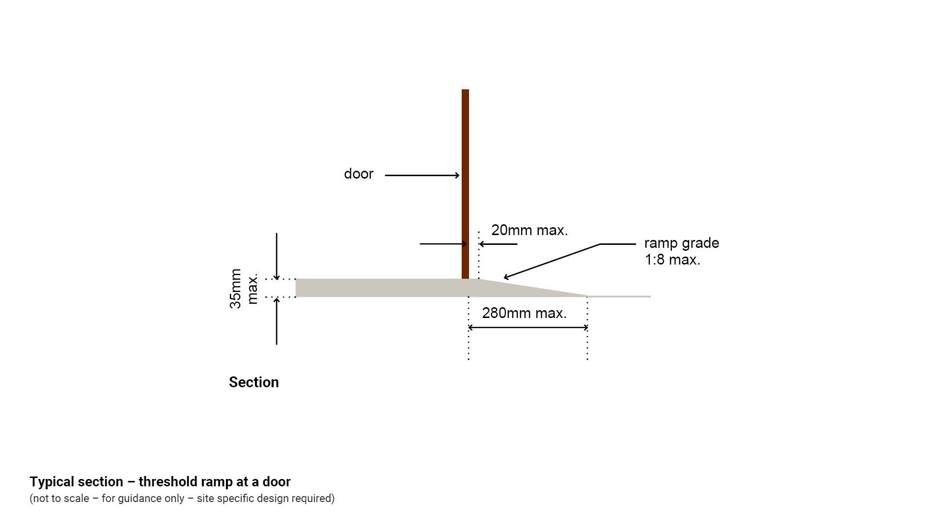
Figure 10: Typical section – threshold ramp at a door
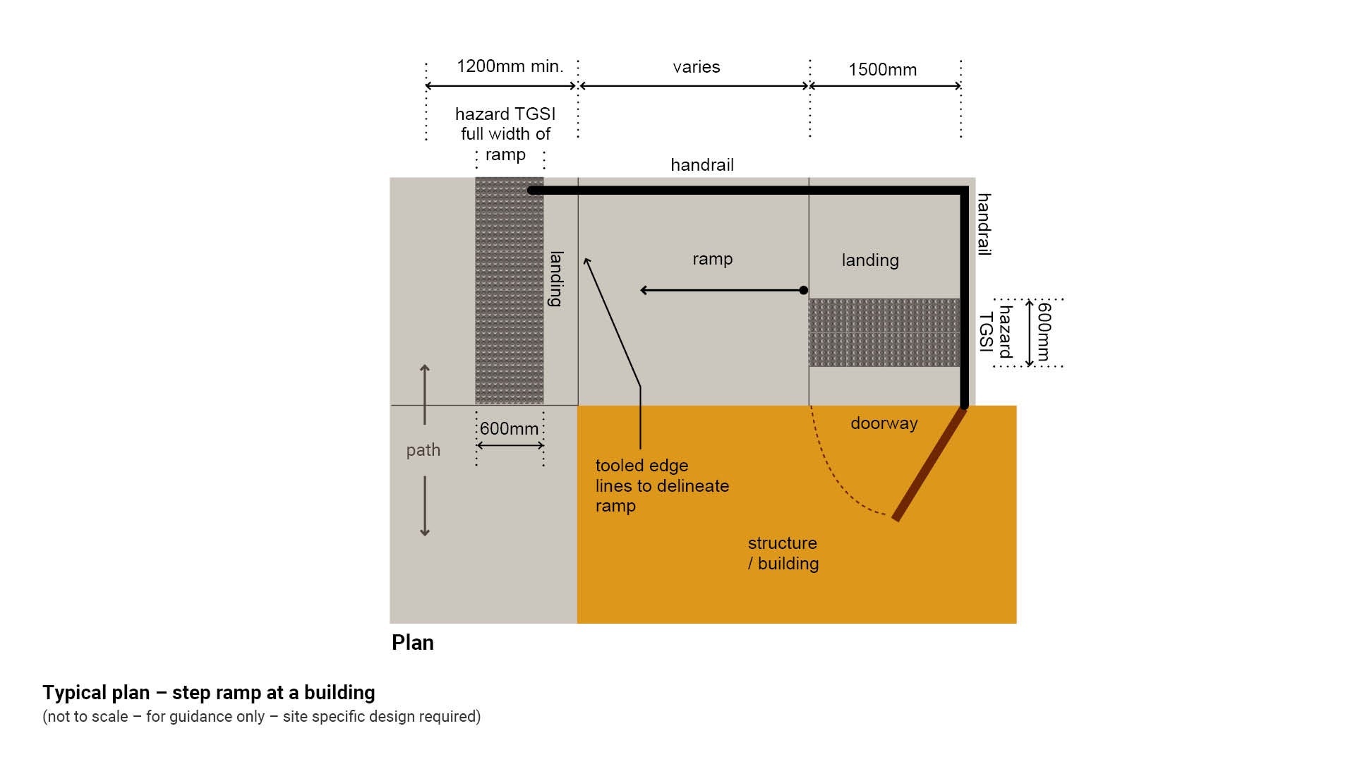
Step ramps
Provide access to a building and contain the following elements:
- Maximum rise of 190 mm
- Maximum length of 1.9 m
- Maximum gradient of 1:10
- Level landing to the top of the ramp
- Level landing to the bottom of the ramp
- TGSI to top and bottom of the ramp.
See the following for further guidance:
- Figure 11: Typical plan – step ramp at a building
- LIM Tactiles.
Figure 11: Typical plan – step ramp at a building
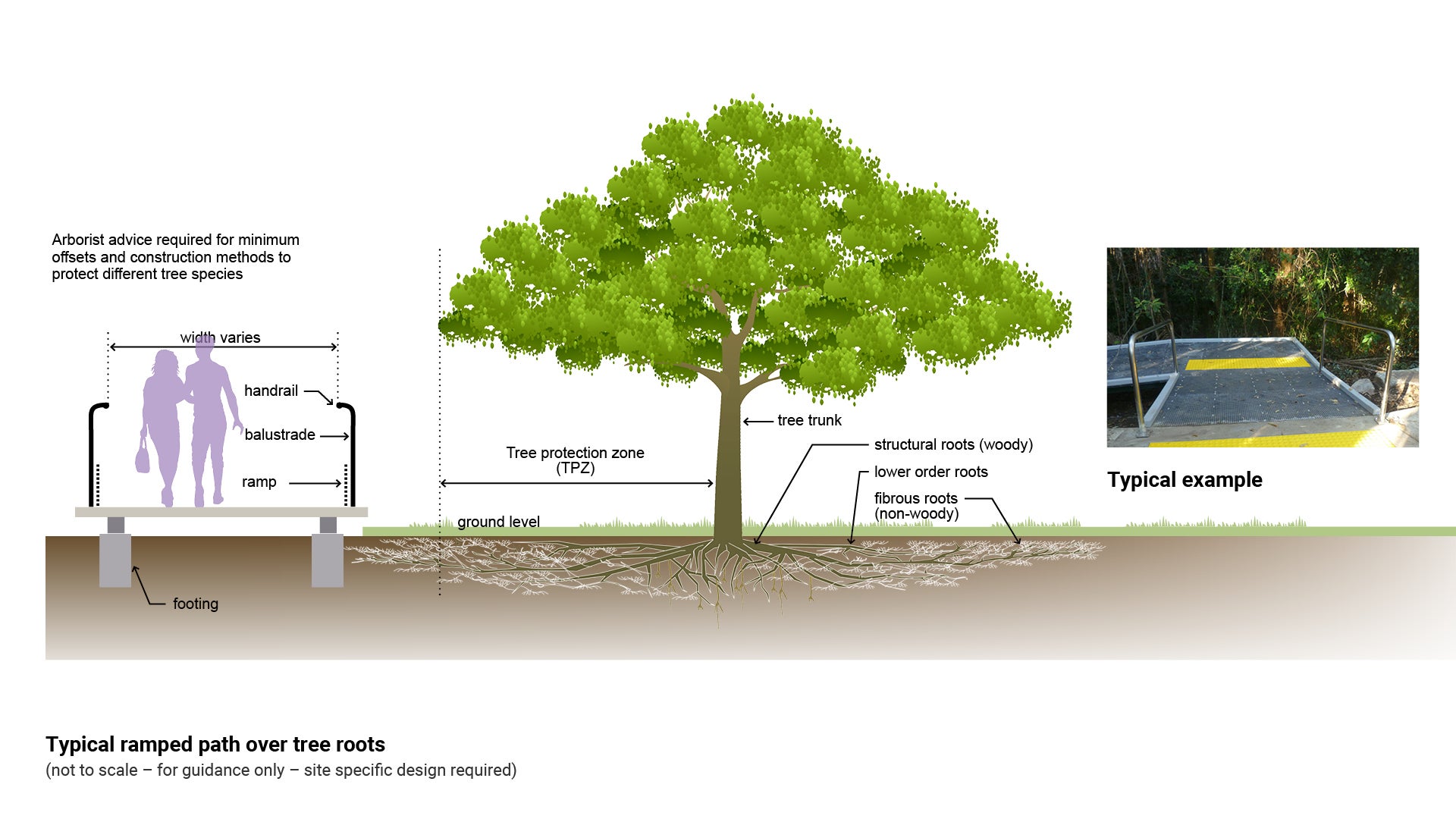
Ramp installation to protect tree roots
One of the advantages of installing ramps, is that they can be elevated over tree root systems reducing potential damage to both the tree and open space infrastructure. The pier footing design reduces the area of direct impact to the tree’s root system, while the elevated design prevents soil disturbance which may indirectly affect tree health. Elevated structures are also less likely to be damaged by tree roots over time.
- Existing trees can suffer direct construction injury through loss of structural and feeder roots or indirect construction injury via reduced access of roots to water, oxygen, nutrients and growing space.
- Locate new ramps as far from existing trees as possible as the best protection mechanism.
Consult a qualified arborist for specific advice about trees under threat of damage.
See the following for further guidance:
- Figure 12: Typical ramped path over tree roots
- LIM Site set up (including tree protection)
- LIM Tree sensitive design (existing and new trees).
Figure 12: Typical ramped path over tree roots
Clearances – ramps
Table 3: Positioning guidance offsets
Embellishment | Distance from | Minimum distance | Reason |
Ramps | New trees | 1.2 m horizontal | Future shade pedestrian safety. |
Ramps | Existing trees | Horizontal tree protection zone (TPZ) varies | See LIM Site set up (including Tree protection) for further guidance. |
Ramps | Clear area to any other embellishment | 2.5 m |
|
Ramps | Tree canopy | 2.5 m vertical height | Pedestrian/cyclist safety clearance. |
Ramps | A perpendicular path of travel | 900 mm | To prevent handrail and TGSI protrusion to path of travel. |
This component is currently in development