Water sensitive urban design (WSUD)
Design - stormwater management options
Requirements for effective stormwater management that involve a series of treatment stages designed to improve water quality and reduce environmental impacts.
Stormwater management options
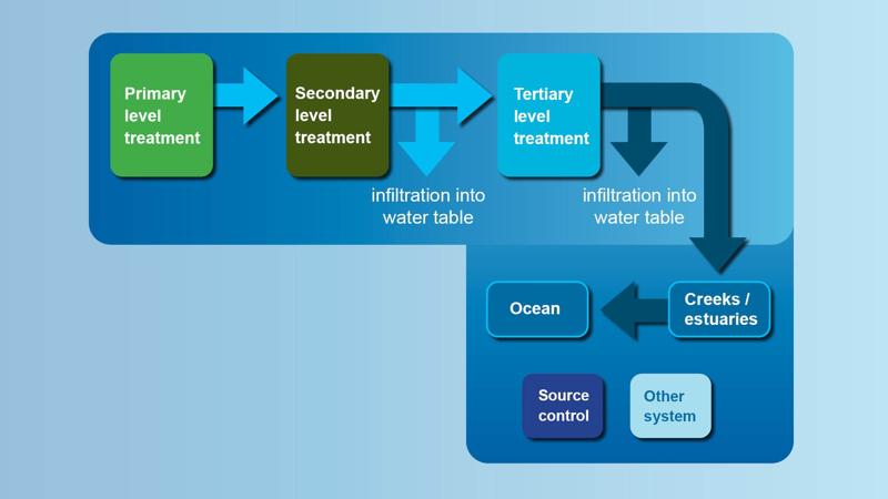
Treatment levels for stormwater structural controls, as part of a treatment train, include:
- Primary treatment – screening, isolation, separation, settling
- Secondary treatment – absorption, filtration, flocculation, settling
- Tertiary treatment – (polishing) aeration, biological decomposition, biological uptake, disinfection, fixation, nitrification, denitrification, oxidation, solar treatment, volatilisation, settling.
The following options may be used to reduce the volume of stormwater runoff:
- Source control devices – systems which reduce the volume of stormwater runoff flowing into the receiving environment. e.g. rainwater tanks, porous surface treatments systems.
- Other systems – systems which may utilise stormwater runoff for the benefit of another asset. e.g. stormwater harvesting and re-use (such as irrigation) to replace potable water use.
See Figure 4: Stormwater management options.
Figure 4: Stormwater management options
Treatment train
A treatment train is a combination of treatment systems/levels, designed to effectively intercept, moderate and eliminate gross pollutants (litter) from stormwater runoff or groundwater. The overall goal is to enhance and preserve natural waterways while mitigating flood risk and damage to life and property.
When used appropriately in collaboration with adequate land management practices, treatment trains provide a holistic approach to WSUD and strengthen the function of natural wetlands, waterways and marine environments.
Standalone treatment systems (e.g. swales, bio-retention systems etc.) are not efficient in removing all pollutants. Generally a treatment train approach is required, however with small catchments the stormwater can be directed to a bio-retention basin, and it may be the sole device used to treat the stormwater to the required standard.
Problem:
- Pollutants such as excess nutrients, sediment, herbicides, pesticides and other heavy metals introduced by urban, agricultural and industrial uses degrade natural waterways.
Aim:
- A treatment train design is in accordance with the quality and quantity of water entering the system, site constraints and target pollutant reduction.
- Selection and order of treatment systems is imperative for appropriate development of a treatment train.
- A failed treatment system can have a cascading effect downstream, from blockages within the underground pipe network to failed dam walls (such as at detention basins), or ecological damage within the RAMSAR listed wetlands of the Pumicestone Passage in Moreton Bay Marine Park.
- Treatment train design depends on the following:
- location (soils, groundwater, hydrology)
- available space
- land use
- existing management practices
- source of pollutants
- treatment required
- costs (construction, operation. maintenance/monitoring)
- community requirements/expectations.
Within the Sunshine Coast Region, numerous treatment systems are utilised, as outlined below.
See Figure 7: Stormwater treatment train (example).
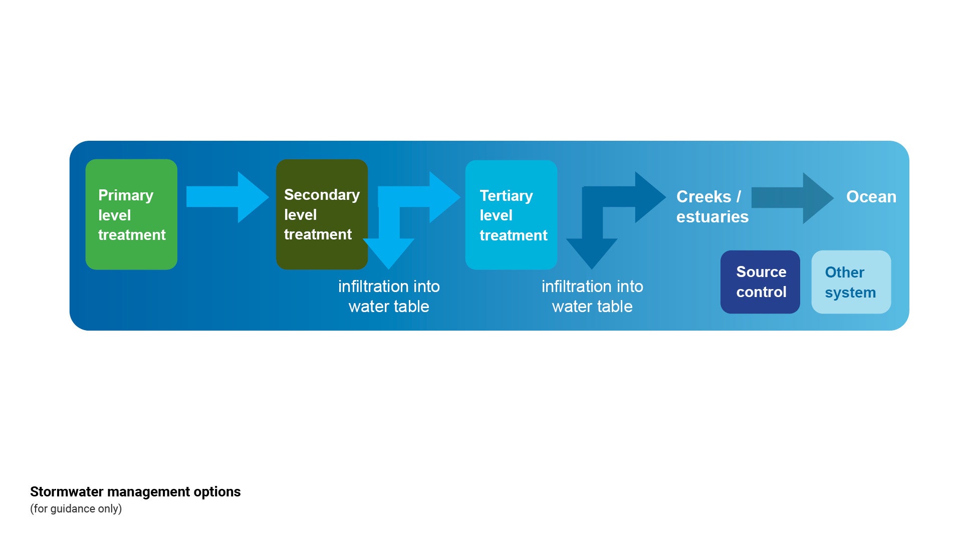
WSUD treatment/methods/and auxiliary embellishments
To provide the best and most robust stormwater treatment, all stormwater quality treatment systems should ideally incorporate an array of primary, secondary and tertiary treatment measures.
See the following for further guidance:
- Figure 5: WSUD treatment/methods and relationship with auxiliary embellishments
- Figure 6: WSUD treatment/methods thumbnail summary
- Table 3: WSUD treatment/methods technical summary.
Note: This category should be read in conjunction with Council's Flooding and Stormwater Management Guidelines.
Figure 5: WSUD treatment / methods and relationship with auxiliary embellishments
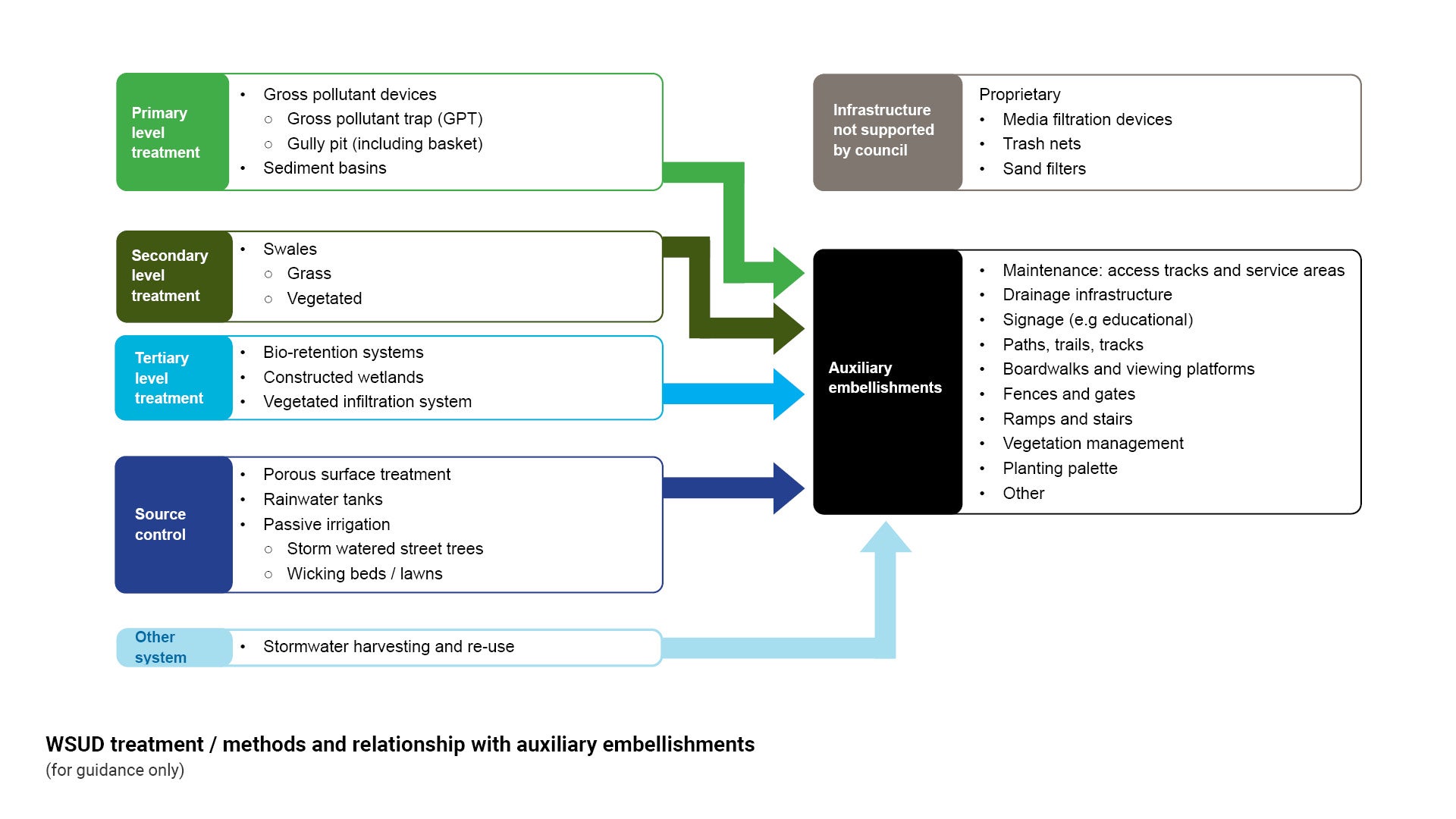
Figure 6: WSUD treatment/methods thumbnail summary
Figure 7: Stormwater treatment train (example)
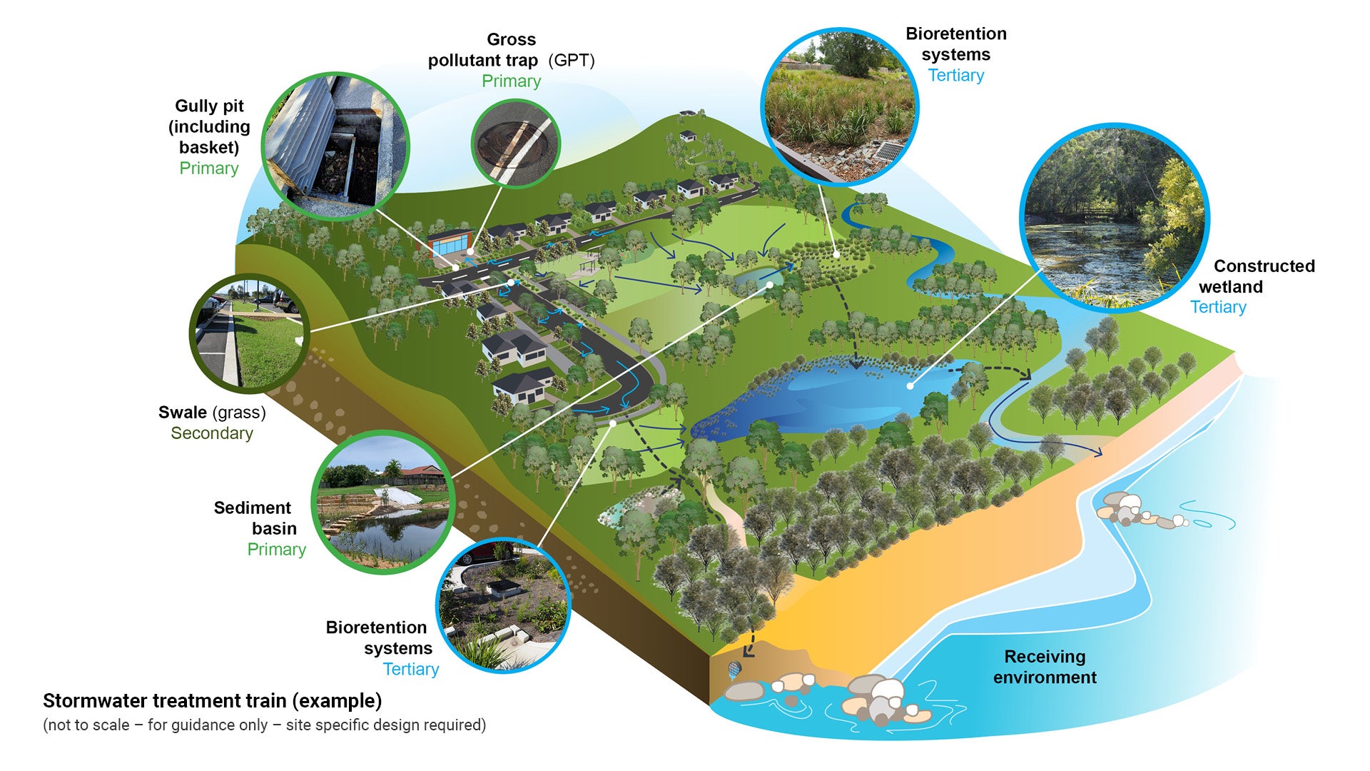
Table 3: WSUD treatment/methods technical summary
Treatment type | Treatment sub-type | Description |
PRIMARY LEVEL TREATMENT Gross pollutant devices  |
| Gross pollutant devices are structures that capture solid waste, e.g. litter, organic matter, coarse sediment |
PRIMARY LEVEL TREATMENT Sediment basins 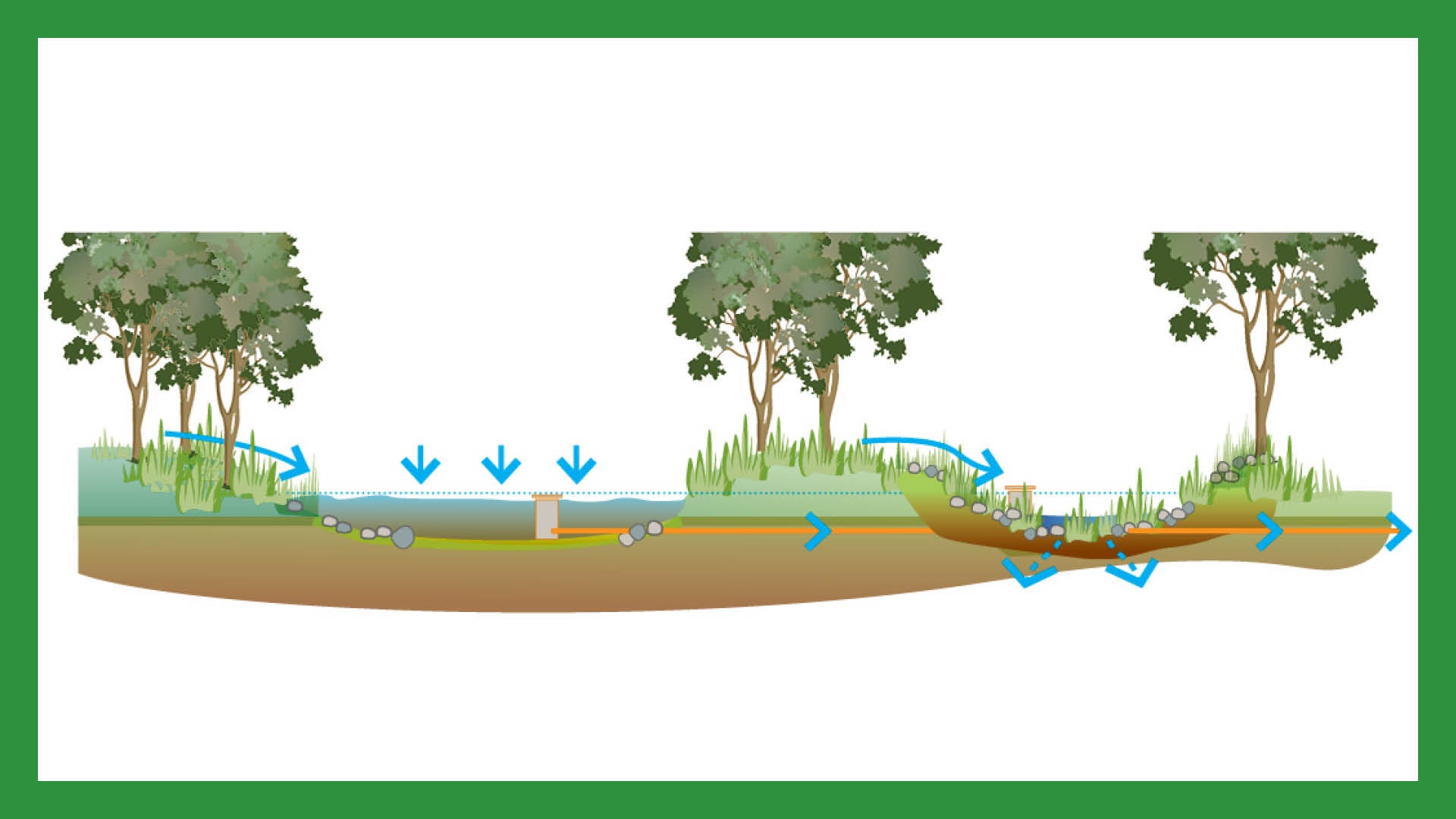 | Sediment basins are stormwater pond systems that are used to trap coarse sediment, and debris, and to regulate flows entering the downstream treatment system. | |
SECONDARY LEVEL TREATMENT Swales 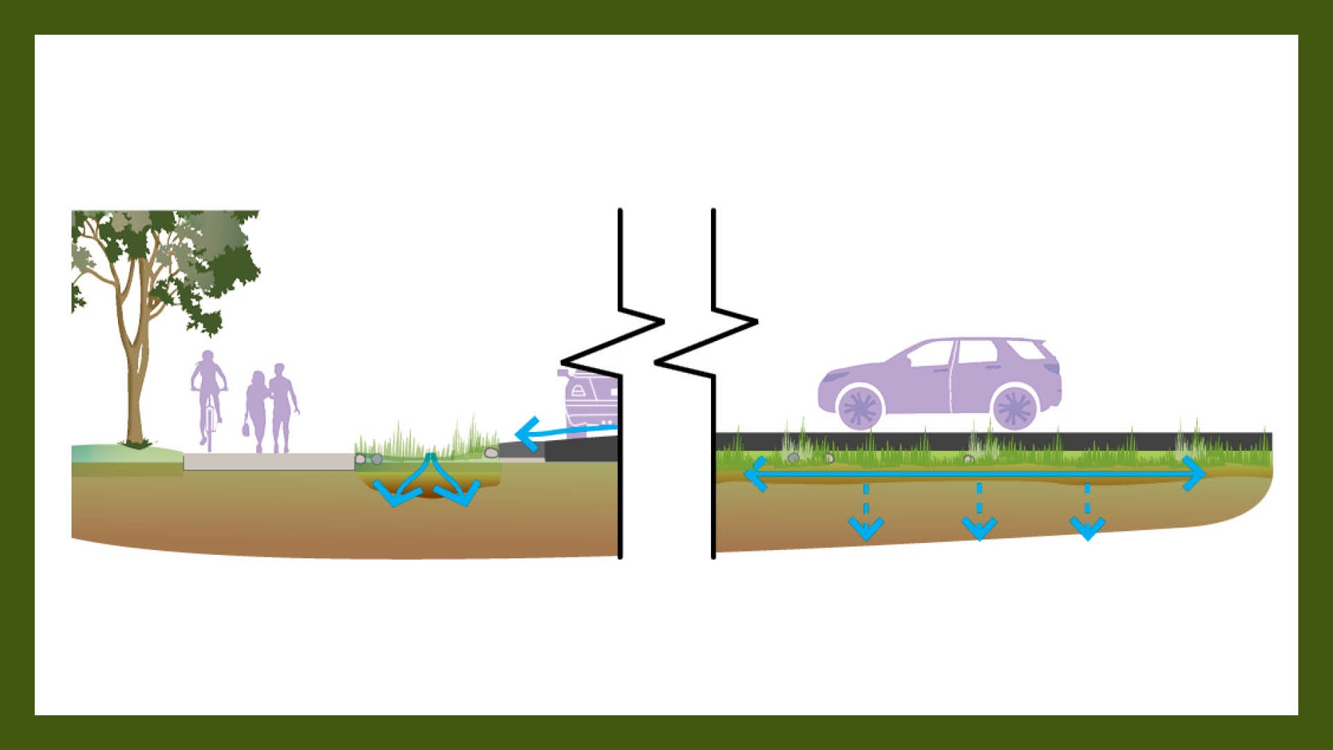 |
| Swales are linear channels (some lined with grass, some vegetated), that collect and transfer stormwater instead of, or in addition to, the underground piped stormwater network |
TERTIARY LEVEL TREATMENT Bio-retention systems 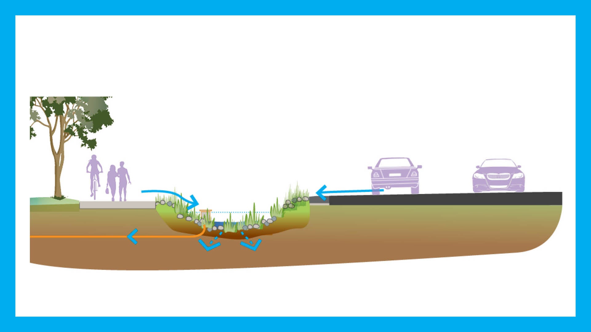 | Bio-retention systems remove sediment and pollutants from stormwater runoff with the use of specifically selected, densely planted vegetation. Surface runoff percolates through multiple layers of filter media, utilising biological uptake, adsorption and fine filtration | |
TERTIARY LEVEL TREATMENT Constructed wetlands 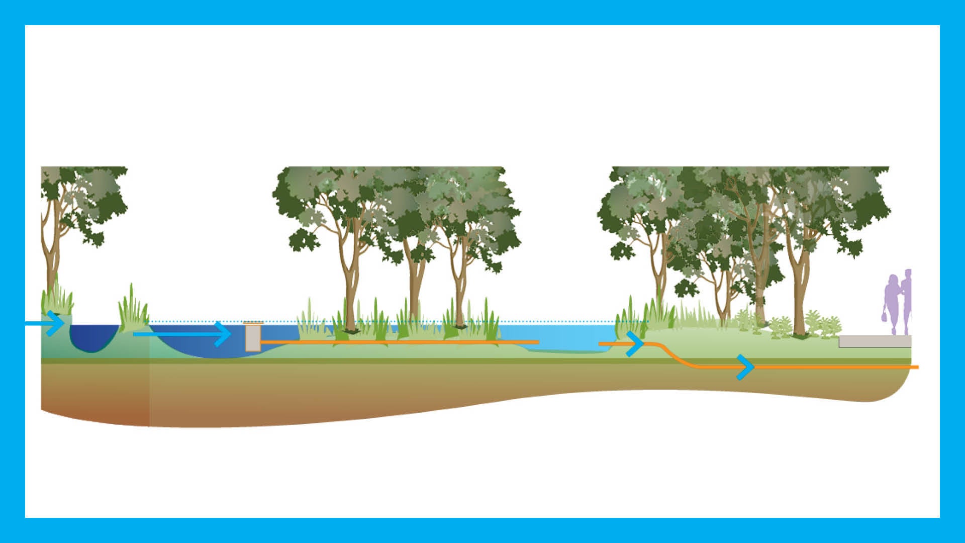 |
| Wetlands are shallow, densely vegetated water bodies which use sedimentation, fine filtration and biological uptake to remove pollutants and excess nutrients from stormwater |
TERTIARY LEVEL TREATMENT Vegetated infiltration system 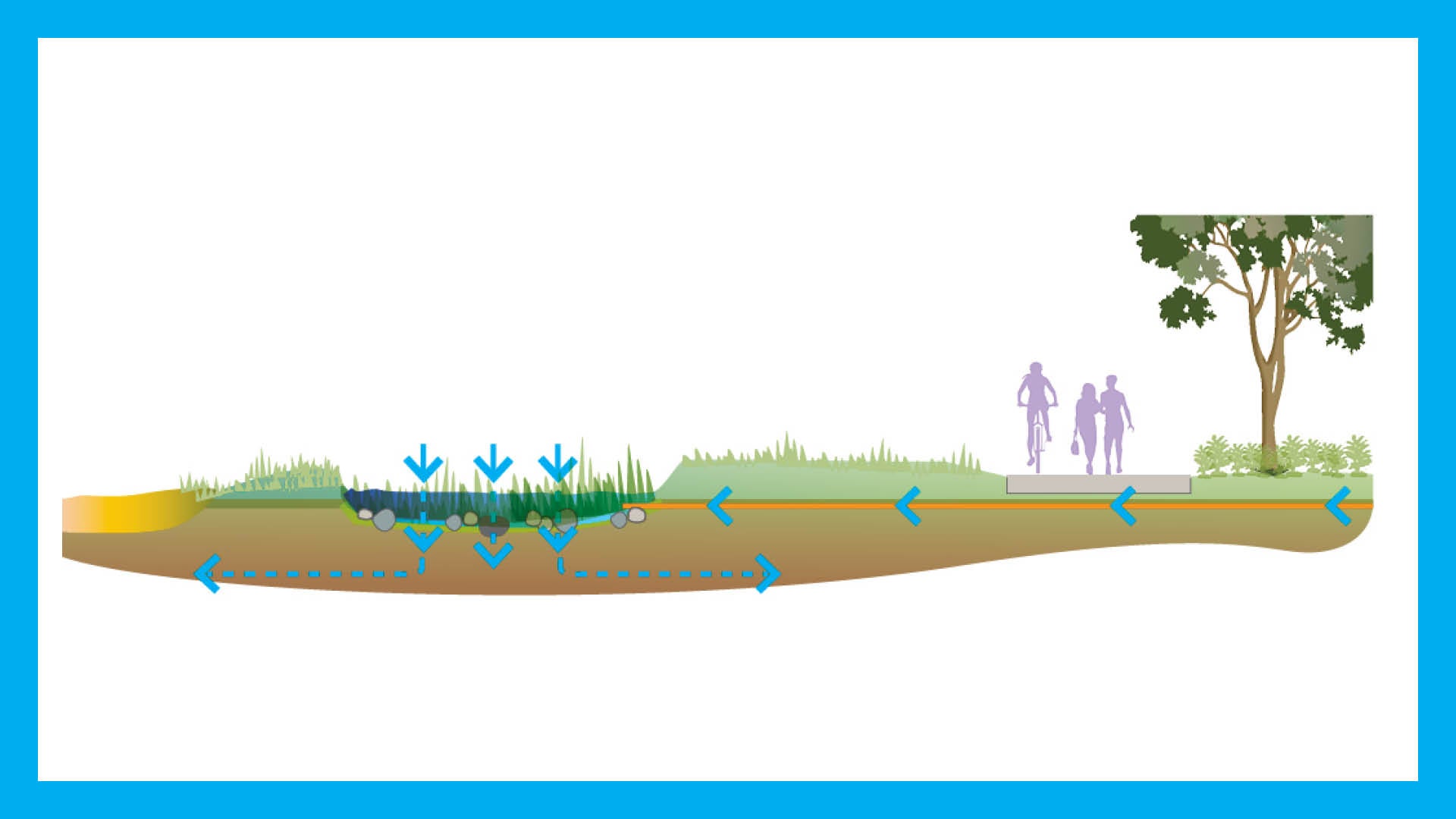 |
| Vegetated infiltration systems collect rainfall, both on site and via stormwater pipes. The roots of the vegetation and the bio-films attached to the plants remove nutrients in the stormwater |
SOURCE CONTROL Porous surface treatment 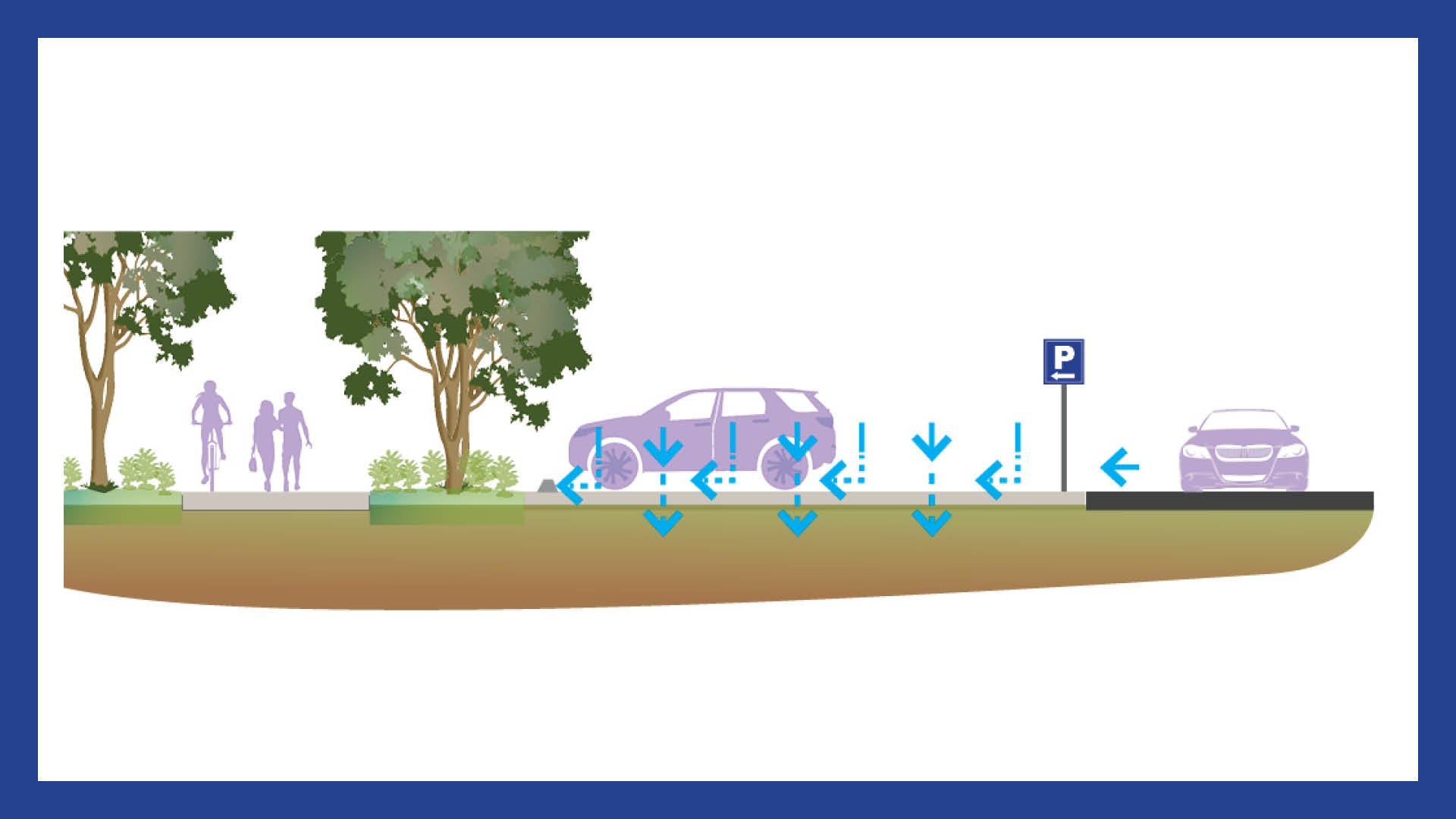 | Porous surface treatments allow water to percolate through to a subsurface course, where it either infiltrates to the surrounding soil, or is filtered back to the drainage system. | |
SOURCE CONTROL Rainwater tanks 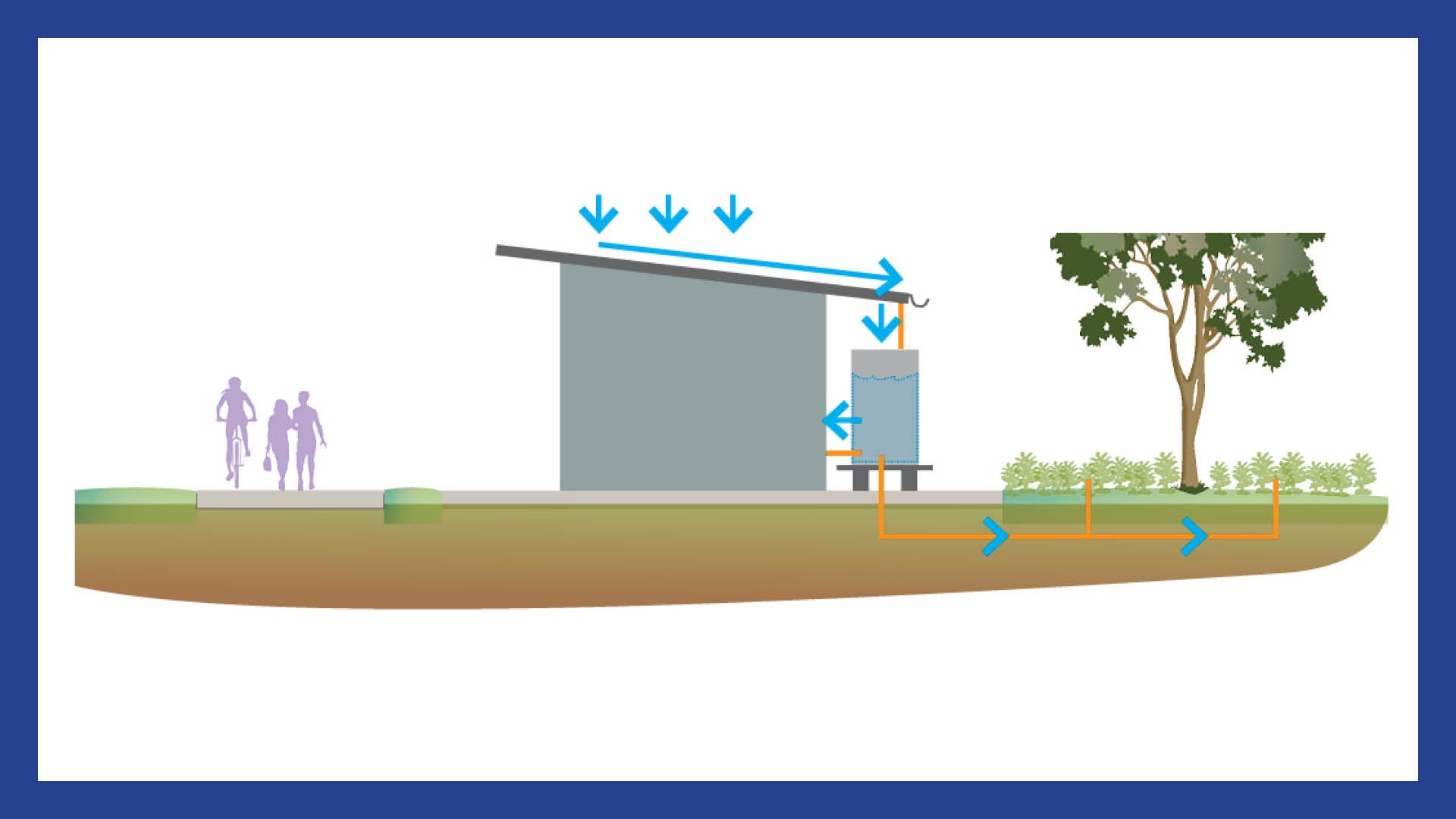 |
| Rainwater tanks are designed to intercept and collect rainwater runoff from impervious surfaces such as building roofs, before it enters the stormwater system |
SOURCE CONTROL Passive irrigation 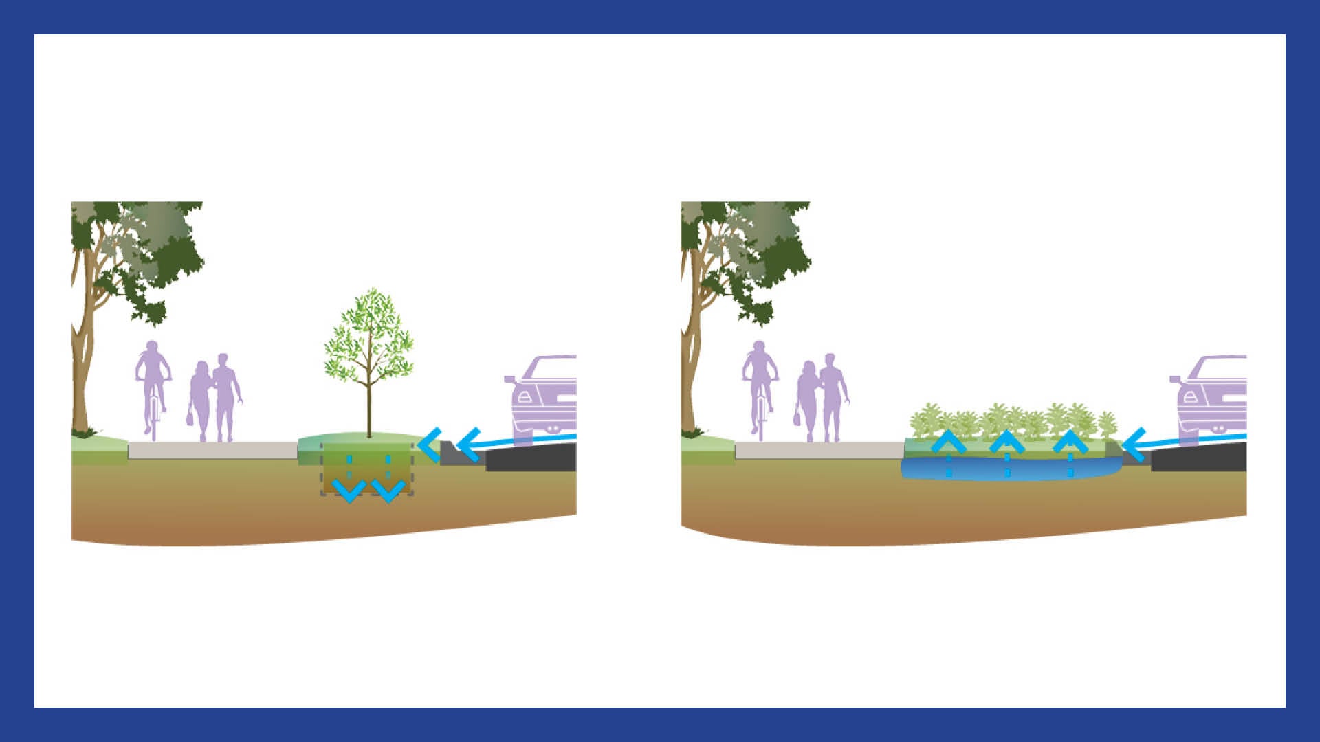 |
| Passive irrigation involves the use of stormwater for irrigation without the need for additional energy resources |
OTHER SYSTEM Stormwater harvesting 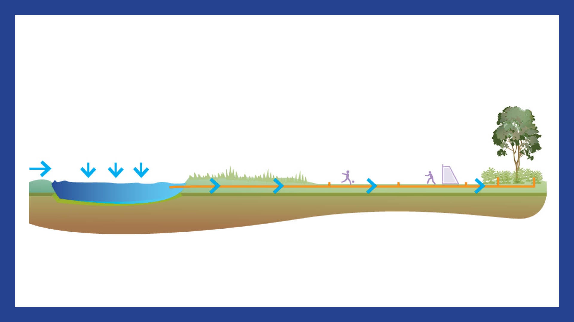 |
| Stormwater harvesting can be defined as the collection, treatment, storage and re-use of stormwater runoff from a variety of sources, including hard surfaces such as roads, car parks and pathways; and natural surfaces such as open space and landscaped areas |
Primary level treatment
Gross pollutant device
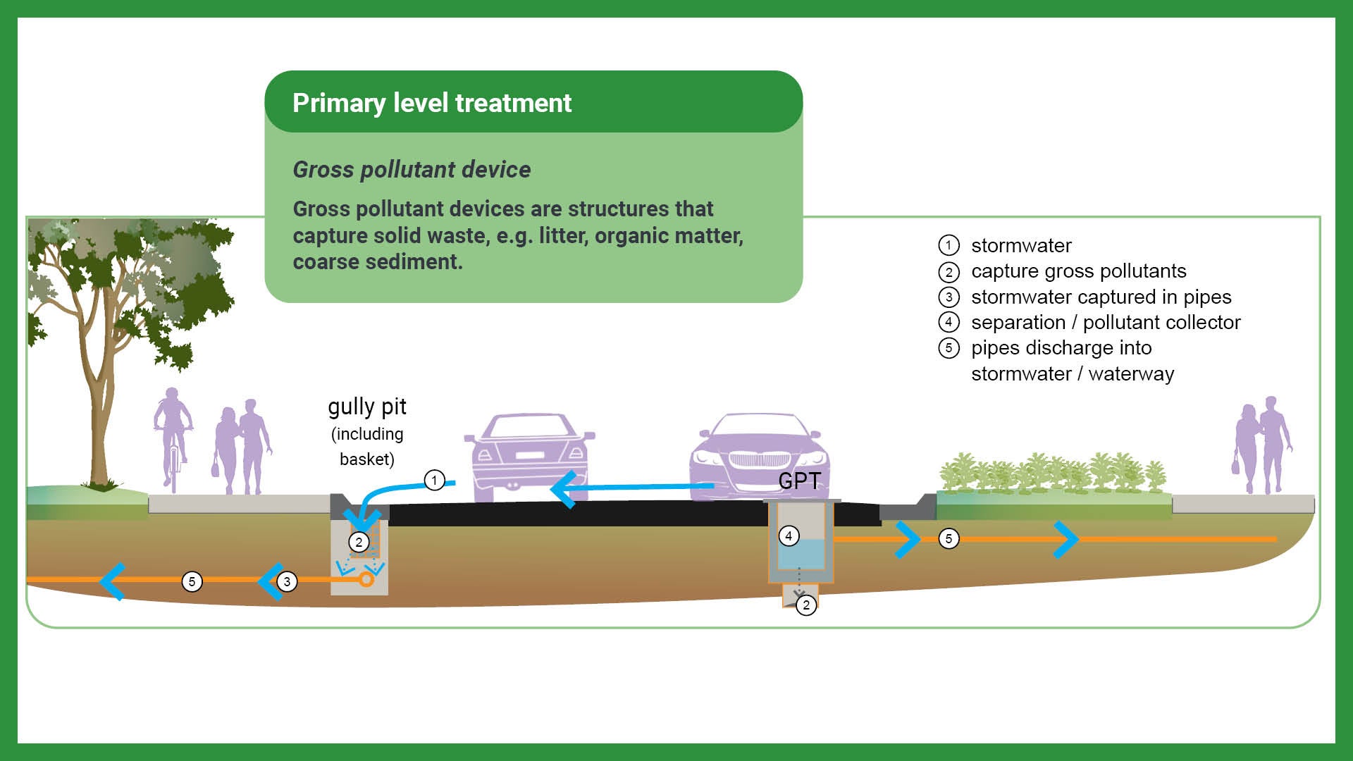
Gross pollutant devices are structures that capture solid waste, e.g. litter, organic matter, coarse sediment.
Most commonly, gross pollutant catchment devices are used as primary treatments within a treatment train, removing large, non-biodegradable pollutants.
There are two types of gross pollutant devices:
- Gross pollutant traps (GPTs)
- Gully pits (including basket).
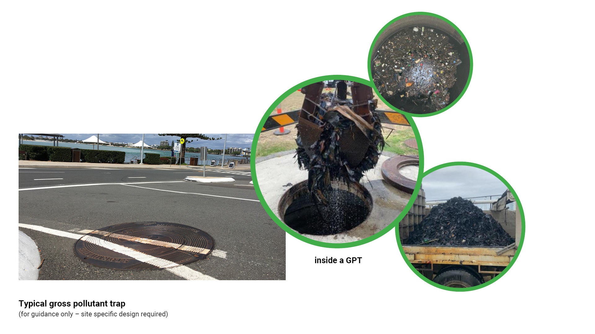
Gross pollutant traps (GPTs)
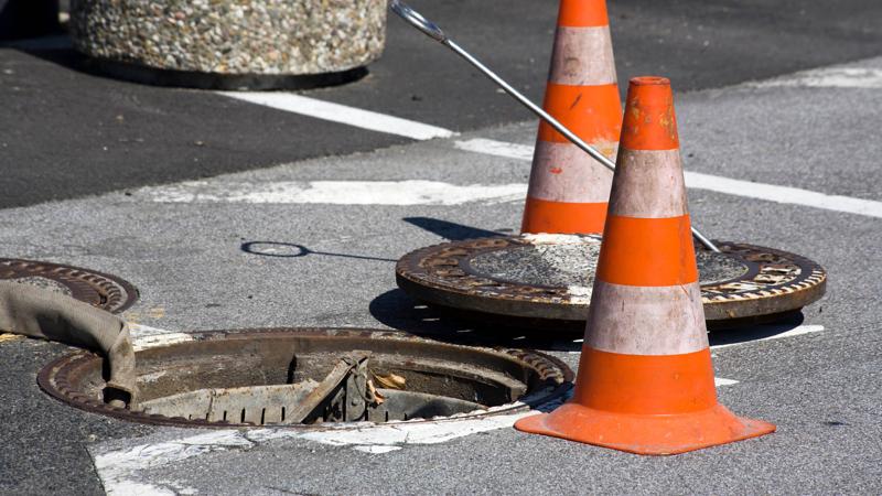
Gross pollutant traps (GPTs)
GPT structures may be suitable for high density developments such as CBDs, industrial areas, shopping precincts or fast food outlets.
Provision
As GPTs are typically not effective in removing nutrients, they are most often used as part of a treatment train with other stormwater treatment elements, e.g. wetlands or bio-retention systems.
Function
By removing gross pollutants, treatment of stormwater can occur more effectively, preventing downstream systems from becoming overloaded.
This is achieved through physical screening of stormwater to remove gross pollutants, rapid sedimentation and other separation processes.
- GPTs trap anthropogenic pollutants, organic matter and coarse sediments in a concentrated location for ease of maintenance.
- GPTs provide pre-treatment within the overall treatment system in areas where there is a high gross pollutant load (commercial, industrial and high density urban). Not suitable for residential or open space.
- Studies have found increased nutrient concentrations downstream of some gross pollutant traps under dry weather flows. There are potential detrimental impacts on downstream water quality where gross pollutant traps are used in isolation (i.e. when not used in conjunction with a vegetated bio-retention or wetland system, or when not adequately maintained to remove pollutants).
Design
GPTs are to be positioned so as to avoid both compromising network performance and tidal inundation.
See the following for further guidance:
- Table 4: Advantages and limitations for use of gross pollutant traps
- Figure 8: Typical gross pollutant trap.
Table 4: Advantages and limitations for use of gross pollutant traps
Advantages | Limitations |
|
|
Figure 8: Typical gross pollutant trap
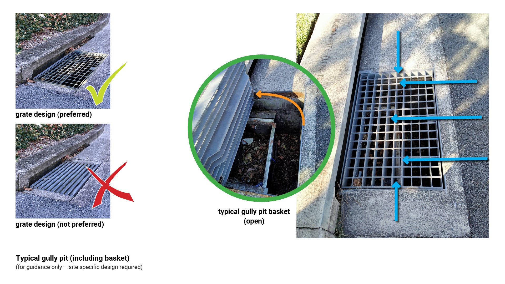
Gully pits (including basket)
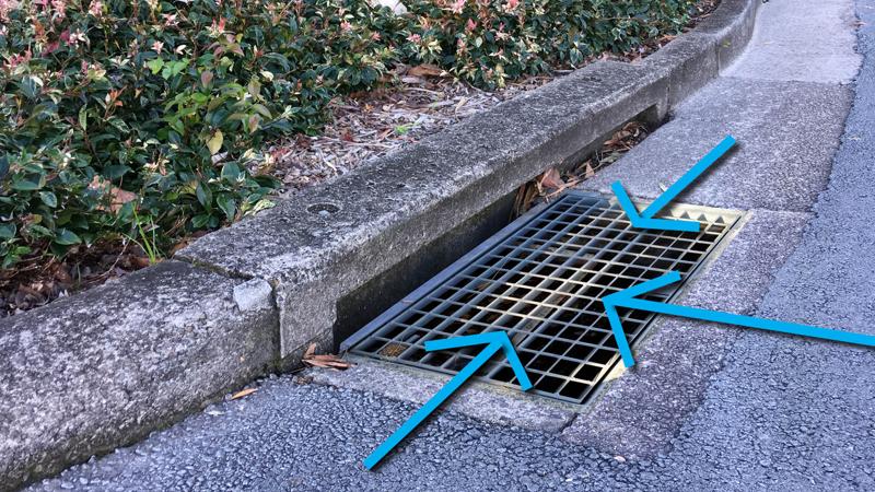
Gully pits can be installed within new and existing underground drains typically in road corridors (kerb and channel) in high litter generation sites such as commercial precincts and tourist areas.
Gully pit baskets sit inside the gully pit capturing pollutants and litter, limiting it entering the stormwater drain system.
Provision
Gully pits are piped entry points to the stormwater network. Gully pit baskets are inserted within the gully pit to capture gross pollutants and organic debris.
The piped stormwater network is used as part of the pre-treatment within the overall treatment train where piped stormwater systems exist.
Function
- Captures large percentage of gross pollutants.
Design
- Max Q bicycle safe grates only. Horizontal lines create the potential for tramlining wheeled devices such as bicycles, wheelchairs, scooters.
- Ensure the grate is flush with the road surface finish level to prevent a hazard for cyclists who often ride in gutters to avoid collision with vehicles.
- The location of a gully pit must be carefully considered prior to install to prevent future flooding.
- Site selection should ensure that basket drains freely.
See the following for further guidance:
- Table 5: Advantages and limitations for use of gully pit (including baskets)
- Figure 9: Typical gully pit (including basket).
Table 5: Advantages and limitations for use of gully pit (including baskets)
Advantages | Limitations |
|
|
Figure 9: Typical gully pit (including basket)
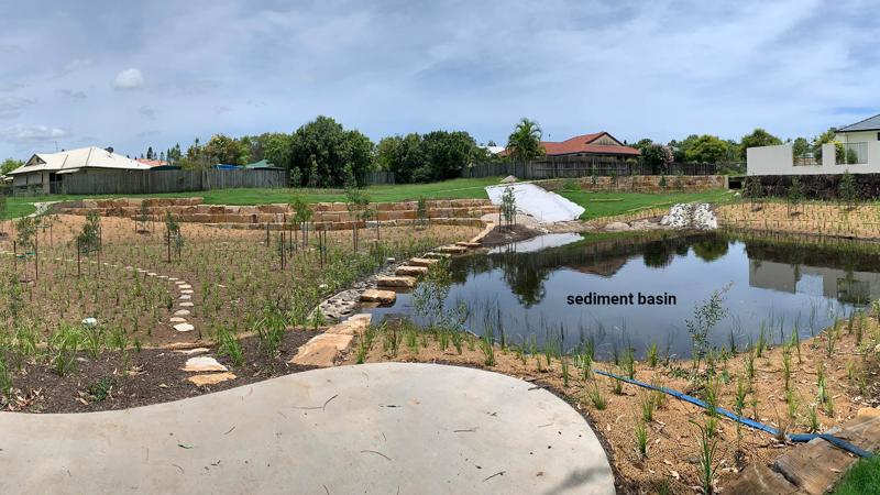
Sediment basins
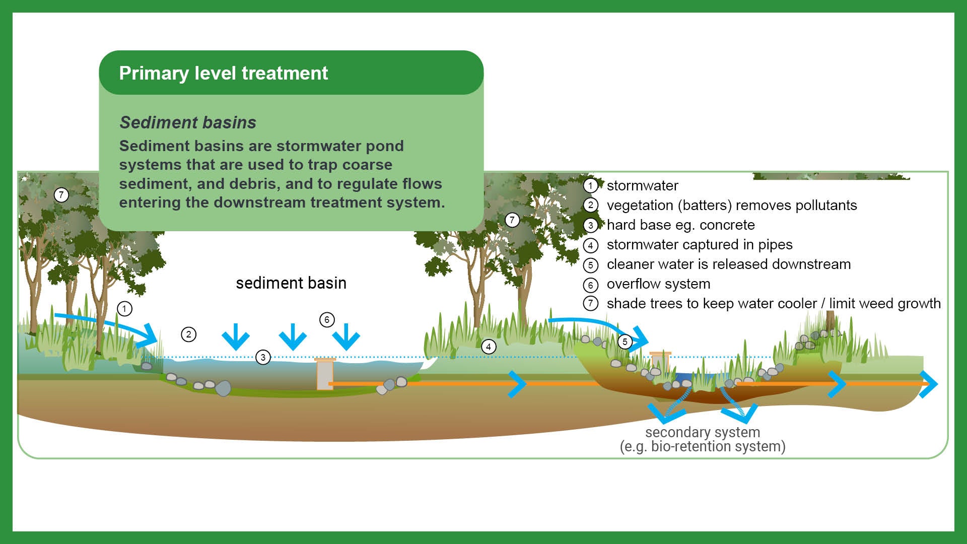
Sediment basins are stormwater pond systems that are used to trap coarse sediment, and debris, and to regulate flows entering the downstream treatment system. These basins are a primary treatment system, using a permanent water column to reduce flow velocities and promote settling.
Sediment basins may be suitable (but not limited to) as either long-term or temporary basins to capture water and disturbed soils. Long-term/permanent environments may be suitable for ‘end of line’ treatments in open spaces. Temporary installations may be suitable for construction sites to capture eroded or disturbed soil during rain events.
Provision
- Sediment basins are not a stand alone treatment.
- To be used for pre-treatment of stormwater prior to entering wetlands or large bio-retention systems.
- Should be placed where most runoff is likely to occur, to mitigate sediment entering watercourses.
- Reduce the velocity of stormwater flow, allowing coarse sediments to settle – gravity pulls the coarse and medium sediments to the bottom of the basin.
Function
- Used for the collection of sediment runoff.
- Cleaner water stays near the surface and flows downstream through the outlet.
Design
- Shade trees should be planted on the banks of sediment basins to reduce water temperatures, limit weed growth and improve the natural amenity of the basin environment. Select appropriate trees, ensuring they do not produce heavy amounts of leaf litter. Too much leaf litter will have negative impacts on the function of the basin.
- Sediment basins are not designed to completely empty. The hard base e.g. concrete or gravel, is utilised to capture the water and hold the sediment. It also provides a useful guide when the basin requires cleaning out, acting as a marker for how deep to dig.
- Maintenance of sediment basins is relatively simple, requiring de-watering (drying of material to minimise disposal costs) and removal of contaminated sediment.
- A suitable site for de-watering and an adequate maintenance access for silt removal should be provided. Maintenance access is to be a ramp on the bank or concrete ramp to accommodate machine entry to basin.
See Table 6: Advantages and limitations for use of sediment basins for further guidance.
Table 6: Advantages and limitations for use of sediment basins
Advantages | Limitations |
|
|
Secondary level treatment
Swales
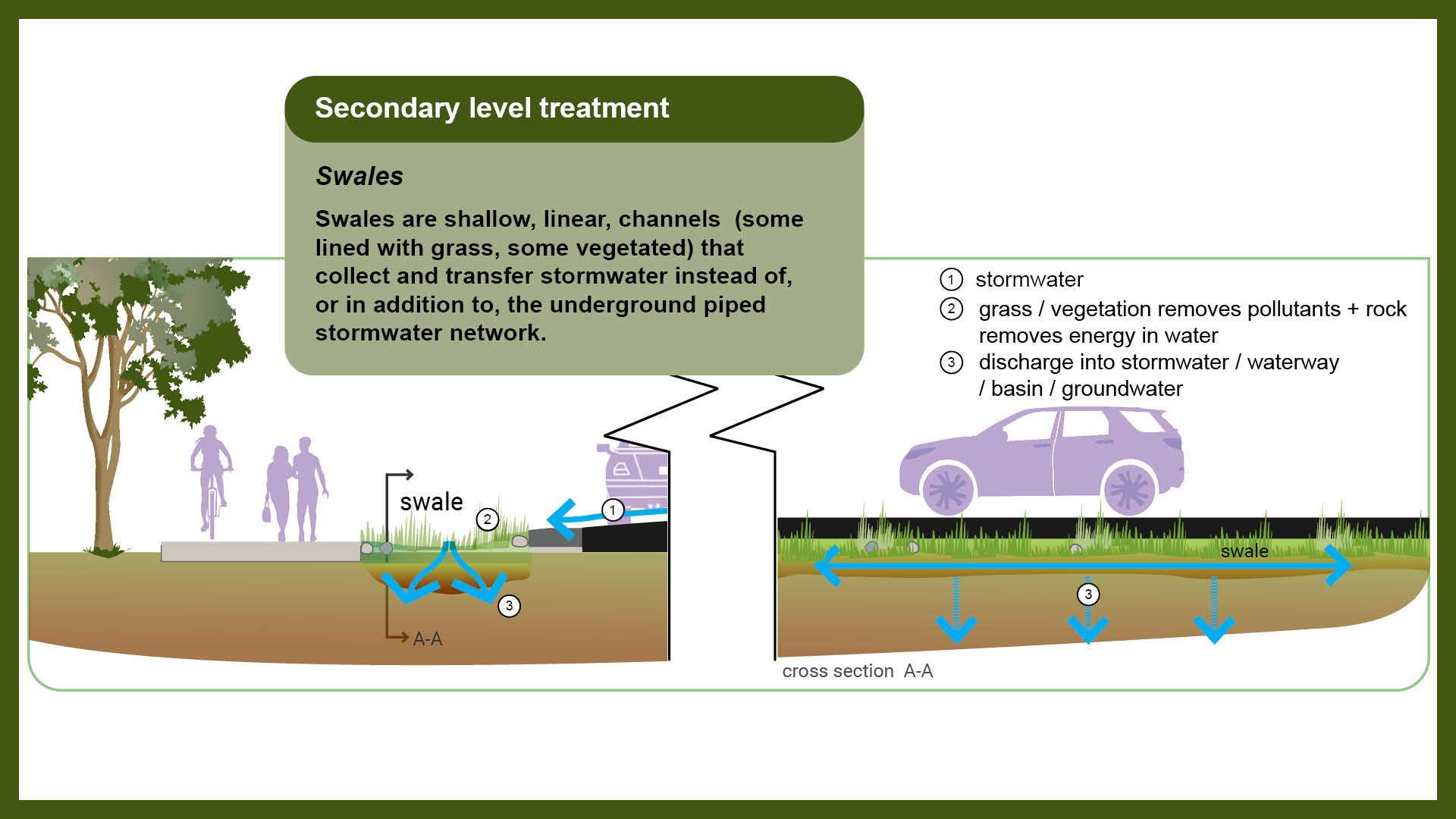
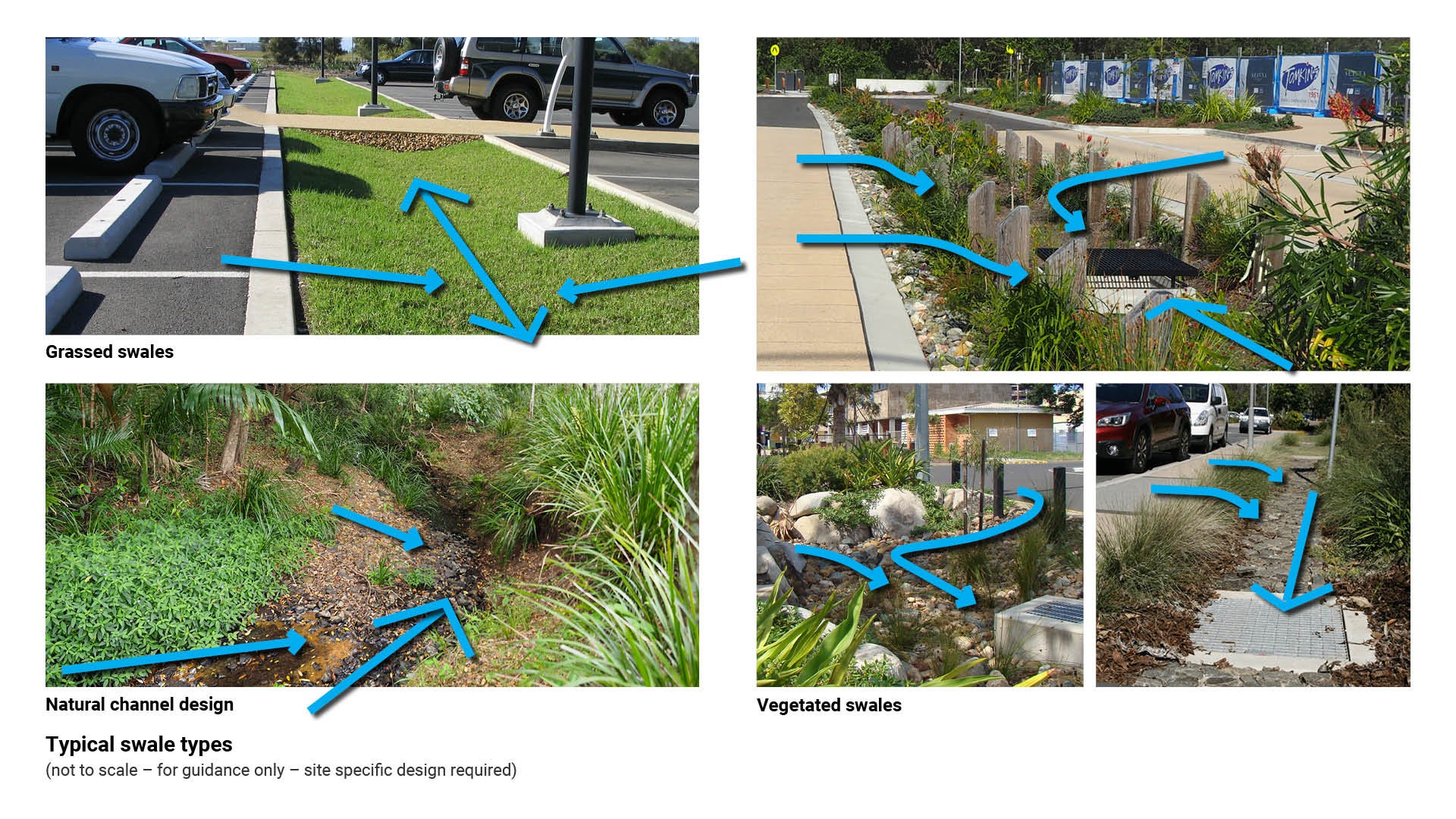
Swales are shallow, linear, channels (some lined with grass, some vegetated) that collect and transfer stormwater instead of, or in addition to, the underground piped stormwater network. The shallow channels are primarily designed for conveying water in a longitudinal manner through a drainage pathway. They can be grass lined, or more densely vegetated and landscaped.
Swales may be suitable for use (but not limited to) along road corridors such as, e.g. road verges and landscape corridors. Swales are best located to help re-vegetate areas, direct water to trees, and to provide water to semi-dry areas.
Provision
To optimise pollutant removal, swales need adequate contact time with stormwater run-off, vegetation and the soil surface.
The following types of swales are used across the Sunshine Coast region:

- Grassed swales – can achieve moderate sediment deposition rates provided flows are well distributed across the full width and length of the swale and the longitudinal grade of the swale is kept low enough to maintain slower flow conditions.
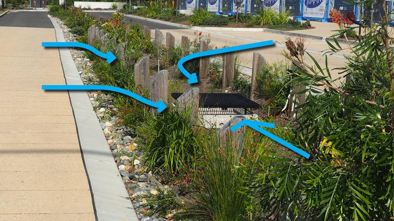
- Vegetated swales – can offer improved sediment retention by slowing flows and providing enhanced sedimentation for deeper flows. Densely vegetated swales have higher hydraulic roughness and therefore require a larger area to convey flows compared to grass swales.
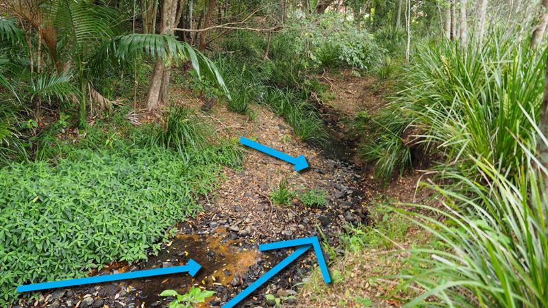
- Natural channel design – These often provide a natural, creek like appearance with incorporated rock riffles, small detention pools and riparian vegetation along embankments – they may also provide elements of fish passage, wildlife and frog habitat – pools may retain some water during drier seasons. These channels are not purposely constructed, however they still achieve a high quality low flow water treatment.
Function
- Overland conveyance of stormwater
- Screening and removal of gross pollutants such as litter and coarse sediment.
- Support for the holistic stormwater system by removing sediments and nutrients from runoff.
- Immobilise pollutants by binding them to organic matter and soil particles, then removal by settling, filtration and infiltration into the subsoil. Pollutants, such as hydrocarbons, may be digested and processed by soil micro-organisms.
Design
In urban areas, swales may be used as an alternative to:
- conventional street nature strips
- road centre median strips
- run-off collection points in carpark areas.
In rural areas with enough space and slope, swales may be used with road sealing to:
- reduce negative impacts from increased stormwater runoff
- connecting impervious areas to existing drainage systems.
See the following for further guidance:
- Table 7: Advantages and limitations for use of swales
- Figure 11: Typical swales types.
Table 7: Advantages and limitations for use of swales
Advantages | Limitations |
|
|
Figure 11: Typical swale types
Tertiary level treatments
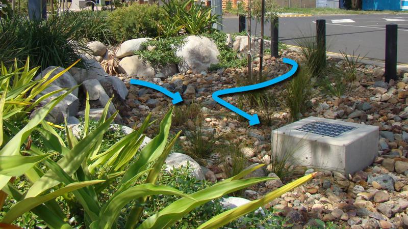
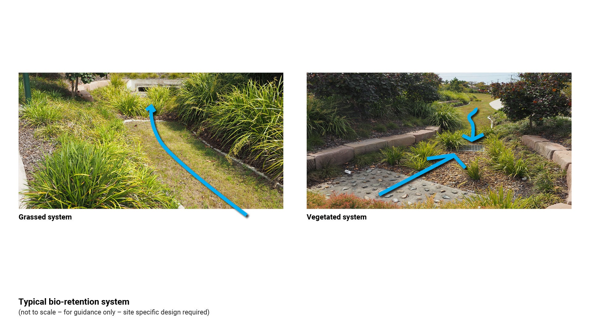
Bio-retention systems
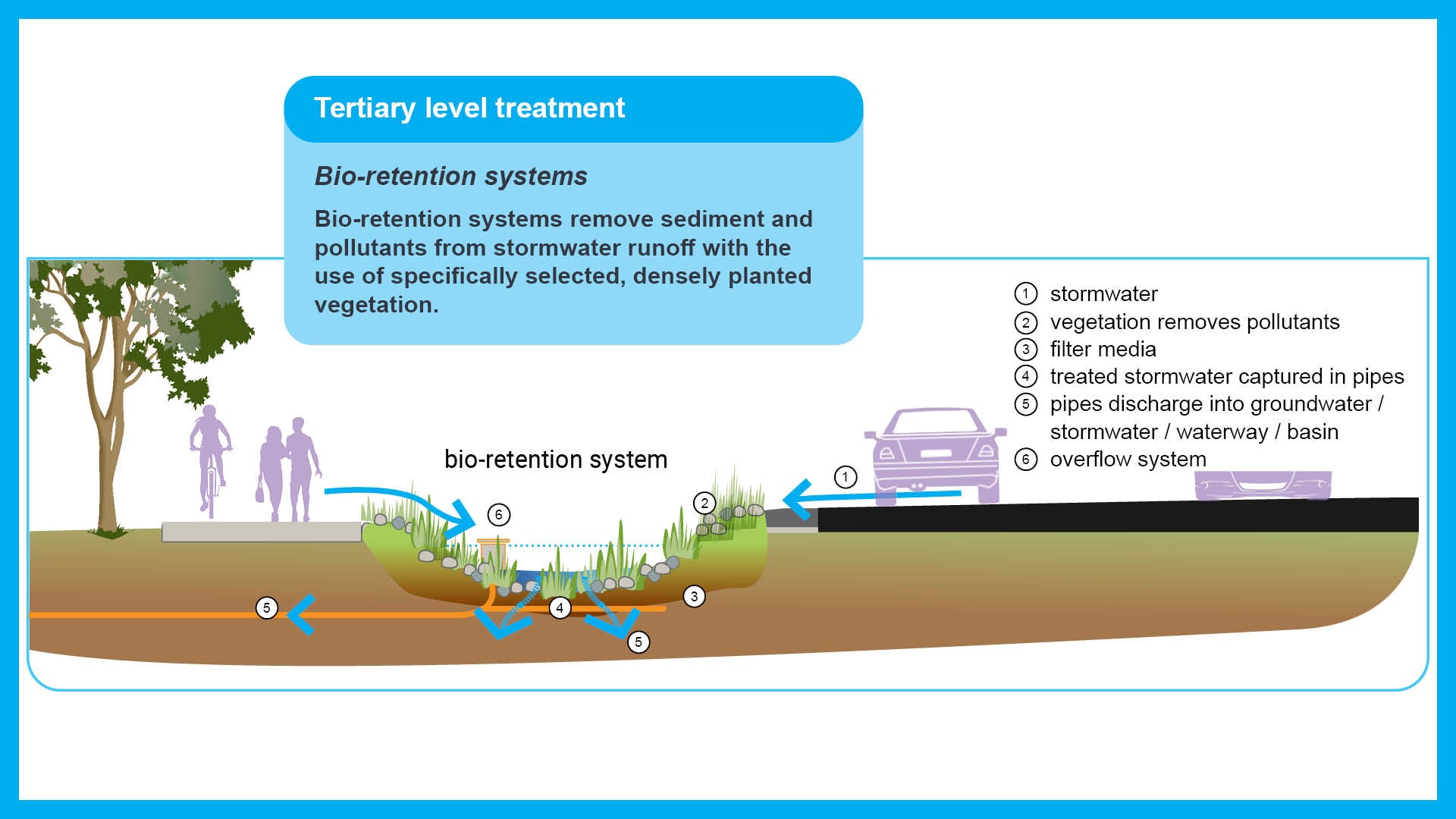
Bio-retention systems remove sediment and pollutants from stormwater runoff with the use of specifically selected, densely planted vegetation. Surface runoff percolates through multiple layers of filter media, utilising biological uptake, adsorption and fine filtration.
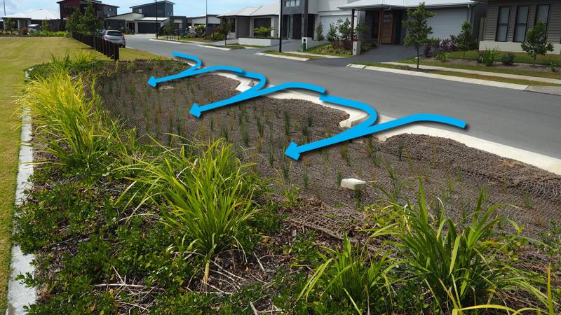
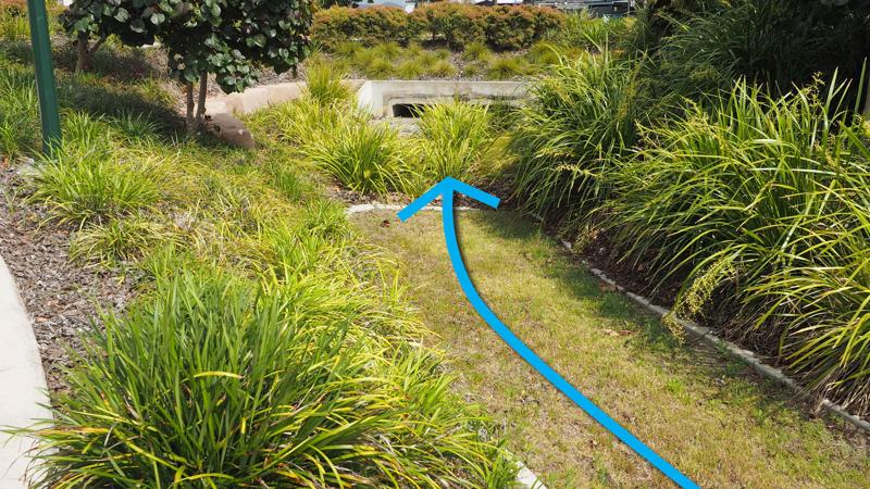
Bio-retention systems that are ‘direct flow – at source’, may be suitable for use in (but not limited to) road verges, streetscapes and carparks where they are found in the form of ‘raingardens’, ‘water gardens’ or ‘walkable bio-retention systems’ to control the flow and direction of water to prevent unnecessary flooding caused by added road infrastructure
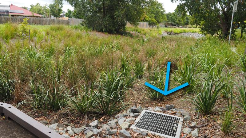
Bio-retention systems that are a ‘pipe system – end of line’, may be suitable for use in open spaces, such as recreational parks and environmental reserves.
Provision
Bio-retention systems are designed to stop stormwater pollutants from entering receiving waters. They are specially designed to filter stormwater runoff from surrounding areas or via stormwater pipes. They use filter media, plants and microbes to biologically treat stormwater. They can be used as 'direct flow' (at source) or 'end of line' systems.
Bio-retention systems can be established at different scales and can take on many different forms. Examples include:
- street tree systems
- bio-retention swales
- bio-retention basin/raingardens.
Function
Bio-retention systems consist of a soil bed planted with suitable vegetation. Stormwater runoff entering the system is filtered through the soil planting bed before being conveyed downstream by either an underground drain system, or infiltrated into the existing subsoil below the soil bed.
Bio-retention systems operate as follows:
- water collects and settles in the base
- water soaks through the filter media trapping rubbish and sediment on the surface and in the fore-bay
- plants utilise the nutrients in the stormwater, and remove some toxins (i.e. hydrocarbons)
- beneficial microbes on the roots of the plants enhance the biological uptake of pollutants
- large systems may contain a sediment basin and/or flow distribution system to manage the large inflows that they receive
- may contain a high flow bypass or an overflow system to reduce flooding.
Design
- Ensure the design takes into consideration pedestrian/cyclist safety, in regards to the transition between the system and pathway.
- Fencing is not preferred as a solution to reducing safety risk.
- Include preventative measures to protect the road pavement from tree roots and seepage.
- The system must be designed so as not to impede pedestrian movement, particularly in road reserves.
The following should be considered for most appropriate plant selection/use:
- Selected species are to have sufficient depth to prevent tree roots from entering any subsurface pipework.
- Select plants with root systems that break down pollutants and help to keep the filter media absorbent.
- Select plants used that are able to tolerate potentially extended periods of dry conditions and sandy soils.
- Two distinct vegetation styles may be utilised depending on the system requirements:
- Low growing species such as shrubs, grasses, sedges and groundcovers (more prevalent due to constraints from tree roots and infrastructure damage)
- Contain both a canopy and an understory - trees may be used where sufficient media depth and surface area is incorporated.
- Council has a preference for native species.
- Established plant height must consider sight line issues and Crime Prevention Through Environmental Design (CPTED).
- Plants with low attrition rates are preferred.
- Plants should be aesthetically pleasing.
- If trees are planted alongside the bio-retention systems, select trees that are appropriate, ensuring they do not produce a heavy amount of leaf litter. Too much leaf litter will have negative impacts on the function of the system.
An appropriate level of landscape design is required to compliment the surrounding landscape character.
Landscape design of bio-retention systems must address stormwater quality objectives while also considering:
- Road visibility (vehicle sight lines)
- Public safety (CPTED guidelines)
- Community character and habitat (indigenous species)
- Equal access.
Hydraulic design is to ensure:
- Effective stormwater treatment
- Minimise damage by storm flows
- Protect hydraulic integrity and function of associated minor and major drainage systems.
Vegetation such as sedges and tufted grasses are required to:
- Cover the whole bio-retention filter media surface
- Be capable of withstanding minor and major flows
- Be of sufficient density to prevent damage to preferred flow paths, scour and re-suspension of sediments
- Continuously break up the surface of the filter media which prevents surface clogging
- Provide a substrate for biofilm growth
- Provide dense vegetation planting to discourage the movement of vehicles onto the bio-retention basin
- Provide a physical barrier (e.g. tree planting)
- Services within road verges must be considered together with access for maintenance.
Walkable bioretention areas – design
Consider all abilities when designing walkable bio-retention systems. A clear pedestrian path of travel is required through the system. Defined edges such as concrete garden edging and stone blocks provide clues for people with low vision.
See the following for further guidance:
- Table 8: Advantages and limitations for use of bio-retention systems
- Figure 12: Typical bio-retention system
- Figure 13: Typical walkable bio-retention systems
- Appendix C - Existing construction sequences to demonstrate the process of real projects managed by council.
- Appendix D - Situations to avoid for successful bio-retention basins. Shows key problem areas council strives to avoid.
- LIM Planting palette for plant species guidance.
Table 8: Advantages and limitations for use of bio-retention systems
Advantages | Limitations |
|
|
Figure 12: Typical bio-retention system
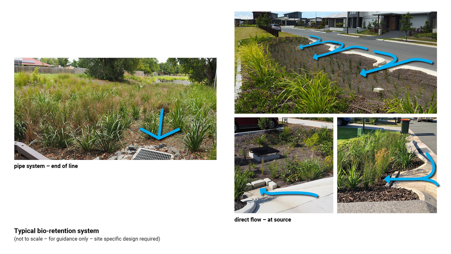
Figure 13: Typical walkable bio-retention systems
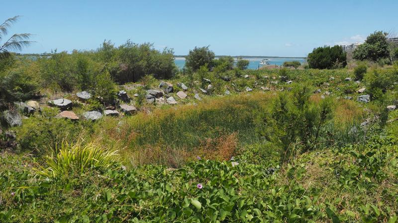
Constructed wetlands
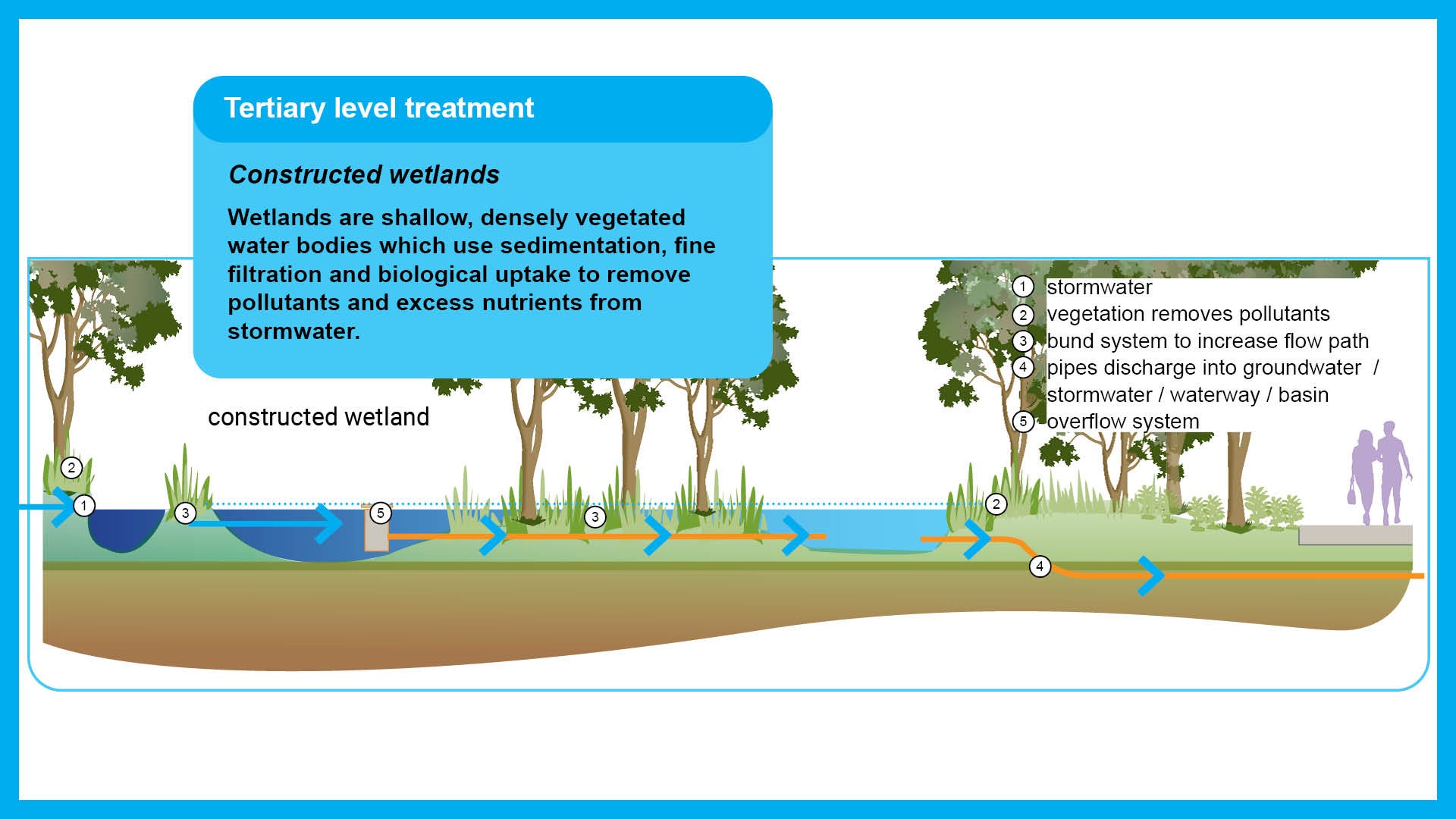
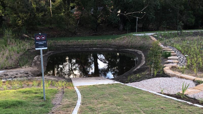
Constructed wetlands are shallow, densely vegetated water bodies which use sedimentation, fine filtration and biological uptake to remove pollutants and excess nutrients from stormwater. Water levels rise during rainfall events, and outlets slowly release flows back to pre-event levels.
Constructed wetlands maybe permanently wet or ephemeral. They may be suitable in open spaces that naturally collect or hold water. Some locations may remain wet all year round and other areas will evaporate seasonally.
Natural wetlands
Natural wetlands are areas of permanent / intermittent inundation, with water that is static or flowing, fresh, brackish or salt, including areas of marine water the depth of which at low tide does not exceed 6.0 m (Queensland Wetland Definition and Delineation Guideline Part A September 2011).
Natural wetlands are not to be used to treat urban stormwater runoff. Runoff must be pre-treated prior to being released into natural wetlands.
Constructed wetlands – general
Provision
- Typically, wetlands are part of a series of treatments (a treatment train).
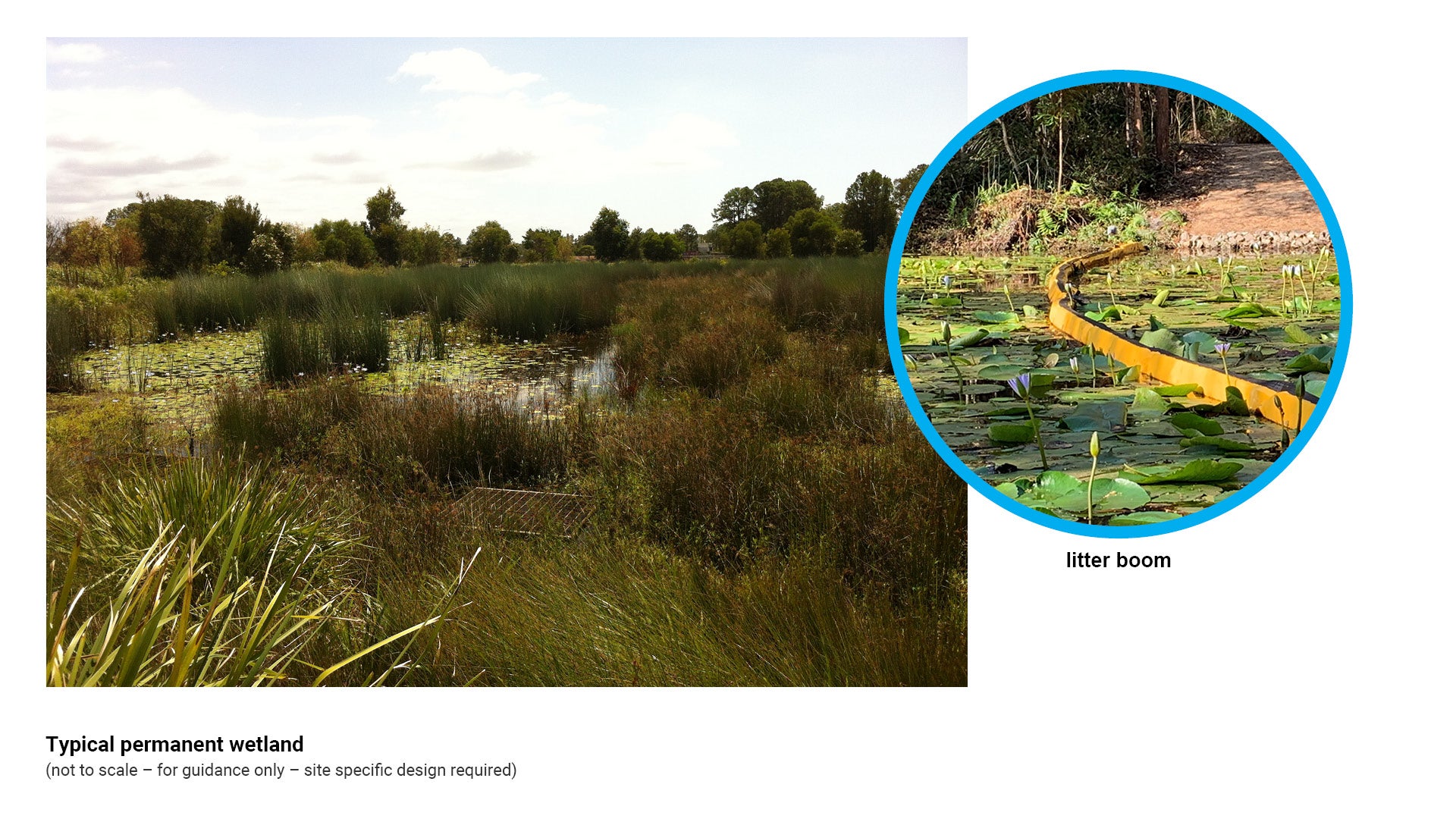
- Other treatments, such as gross pollutant traps and sediment ponds in the inlet zone, protect the wetland by removing coarse sediment and rubbish. Litter booms may also be used where appropriate.
- The wetland removes fine particles and dissolved pollutants like nutrients and heavy metals.
A constructed (artificial) wetland is one built where there was no wetland prior to the construction. Constructed stormwater wetland systems provide a means of treating and removing pollutants from stormwater prior to entering creeks, rivers and oceans. Constructed wetlands should replicate the behaviour of naturally occurring wetlands as far as possible.
Constructed wetlands typically have three parts that work together to help filter stormwater and protect against flooding:
- Inlet zone – a sediment basin that removes coarse sediment
- Macrophyte zone – the main part of the wetland; a shallow area densely planted with aquatic plants, which removes fine particles and dissolved pollutants
- High flow bypass – lets excess water flow around the wetland without damaging the plants.
There are 3 types of constructed wetlands:
- Permanent wetlands
- Ephemeral wetlands
- Floating treatment wetlands (NOT supported by council).
Function
Wetlands work on 3 levels:
- Physical
- Plants are essential parts of a wetland and are used to capture fine particles and trap a high proportion of absorbed pollutants attached to sediment.
- These plants also slow and filter water, which encourages fine sediment particles to settle, and reduce the chance of sediment being scoured or re-suspended in the water during a large storm.
- Biological and chemical uptake
- Slimy micro-organisms called biofilms grow on the surface of plants, absorbing and trapping pollutants, enhancing sedimentation and adhesion to fine suspended particles.
- Pollutant transformation
- Wetlands transform the pollutants in stormwater in a number of ways:
- Their regular wetting and drying cycle stabilises and fixes contaminants, such as phosphorus and metals, in the underlying soil.
- Microbial processes convert pollutants like ammonium and nitrate into nitrogen gas, which is released into the atmosphere (nitrification/de-nitrification).
- Ultraviolet (UV) treatment in open water areas provides some disinfection.
Design
- Wetlands may have open water ponds at the inlet and outlet, but should otherwise be planted so densely that the water is not easily visible. This avoids problems such as algal growth and sediment re-suspension through wind and wave action.
- Wetland plants must be protected from overly high flow velocities and being frequently inundated with water for long periods of time.
See the following for further guidance:
- Table 9: Advantages and limitations for use of constructed wetlands
- Figure 14: Typical permanent constructed wetland
- Appendix C - Existing construction sequences to demonstrate the process of real projects managed by council.
Table 9: Advantages and limitations for use of constructed wetlands
Advantages | Limitations |
|
|
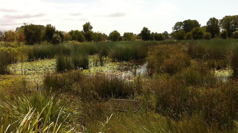
Permanent wetlands
Function
Permanent wetlands are always, or nearly always, inundated. They do not dry out, and lose a relatively small percentage of their volume even during unusually dry periods. They are dominated by aquatic plants and also:
- Support a broad range of wildlife, such as fish, reptiles and birds
- Can be used by the full complement of wetland-breeding amphibians and most invertebrates
- Wetland macrophytes are common.
See Figure 14: Typical permanent wetland.
Figure 14: Typical permanent constructed wetland
Ephemeral wetlands
Function
Ephemeral or short hydroperiod wetlands dry out in most years, may be dry for years and may only be wet for a short period (ephemerally).
Wet and dry wetlands replicate the Australian natural environment. They provide:
- Improved weed control – weeds die when wetland is dry
- Better at fixing pollution to sediment
- Important resources to local and migratory species.
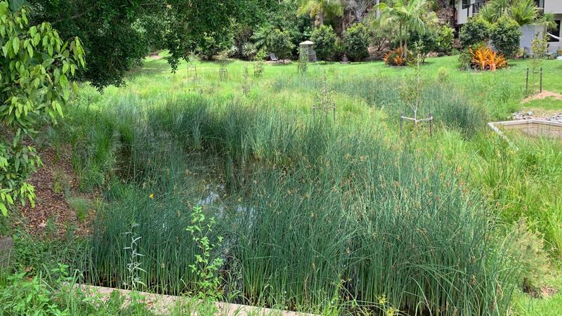
Vegetated infiltration systems
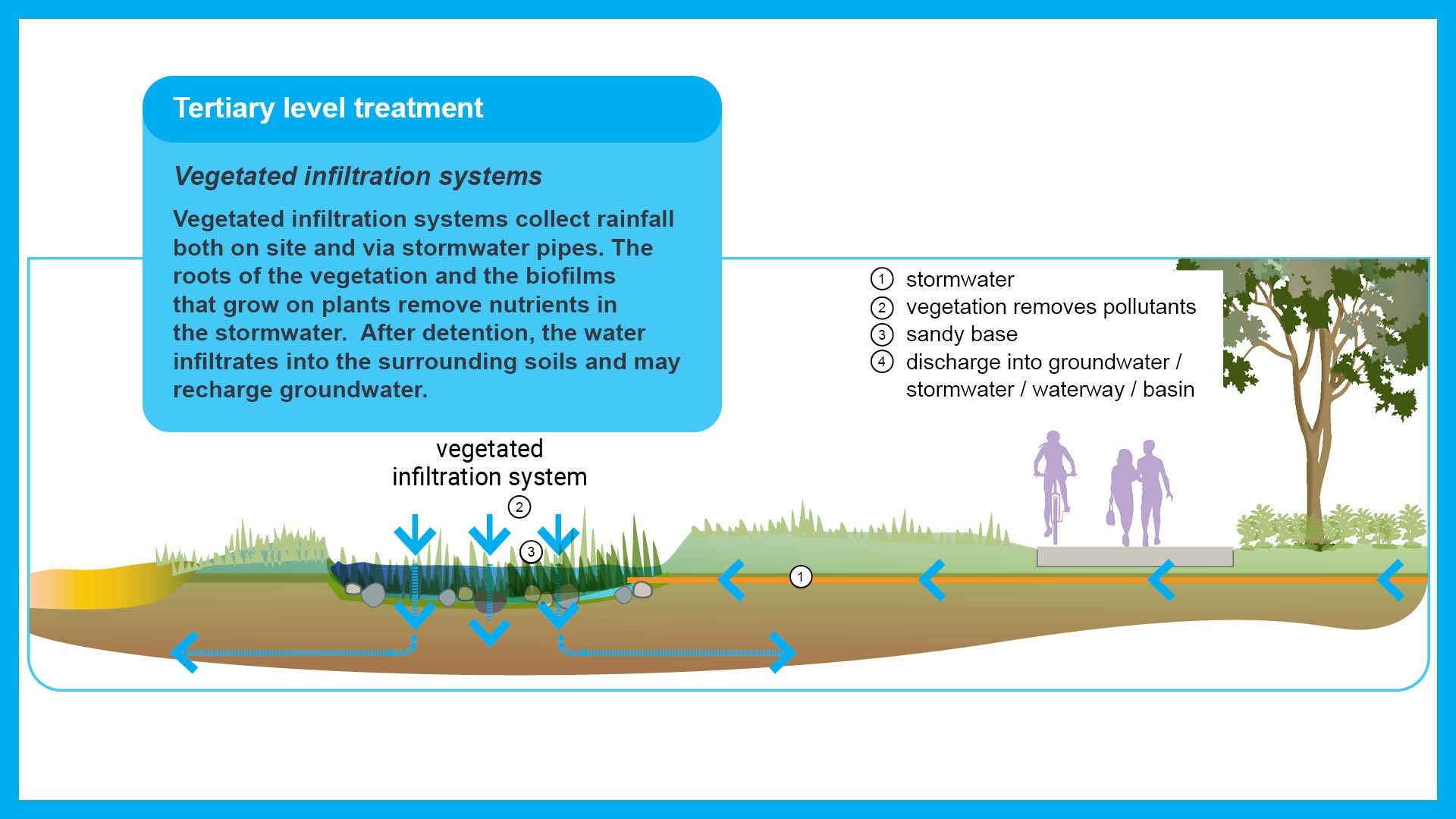
Vegetated infiltration systems collect rainfall both on site and via stormwater pipes. The roots of the vegetation and the biofilms that grow on plants remove nutrients in the stormwater. After detention, the water infiltrates into the surrounding soils and may recharge groundwater. They are most successful with soils that have a high infiltration rate.
Vegetated infiltration systems allow stormwater to infiltrate into the subsurface after being captured in a basin or when flowing slowly along a channel. These are typically located in areas of high permeability e.g. sandy soils.
Provision
The purpose of these systems is to treat diverted stormwater. The sediment in the runoff settles onto the basin floor while the remaining water infiltrates through the soils below.
These systems may be used where discharge to a natural system is required, or in situations where groundwater recharge is to be maintained at pre-development runoff volumes.
Moderately to highly permeable in-situ soils i.e. sandy loams to sandy soils, are best suited for vegetated infiltration systems. Geotechnical investigations are required to determine the ability of site soil to accept infiltration.
Vegetated infiltration systems should not be located in areas of impermeable soils. In areas of contaminated land, a risk assessment should be undertaken prior to design and construction.
Function
The main functions of these systems are:
- Typically used in public open space applications
- Composed of a natural or constructed depression
- Designed to capture and store runoff on the ground surface prior to infiltration into in-situ soils
- Best suited to highly permeable (e.g. sandy) soils
- Can be planted out to blend into the surrounding landscape
- Vegetation provide water quality benefits, and root systems may prevent clogging of the basin floor
- Pre-treatment may be required for high sediment catchment areas
- Plants in an infiltration basin should be able to tolerate periods of prolonged inundation or extended dry periods.
- Biological and chemical uptake
- Slimy micro-organisms called biofilms grow on the surface of plants, absorbing and trapping pollutants, enhancing sedimentation and adhesion to fine suspended particles.
See Table 10: Advantages and limitations for use of vegetated infiltration systems for further guidance.
Table 10: Advantages and limitations for use of vegetated infiltration systems
Advantages | Limitations |
|
|
Source control treatments
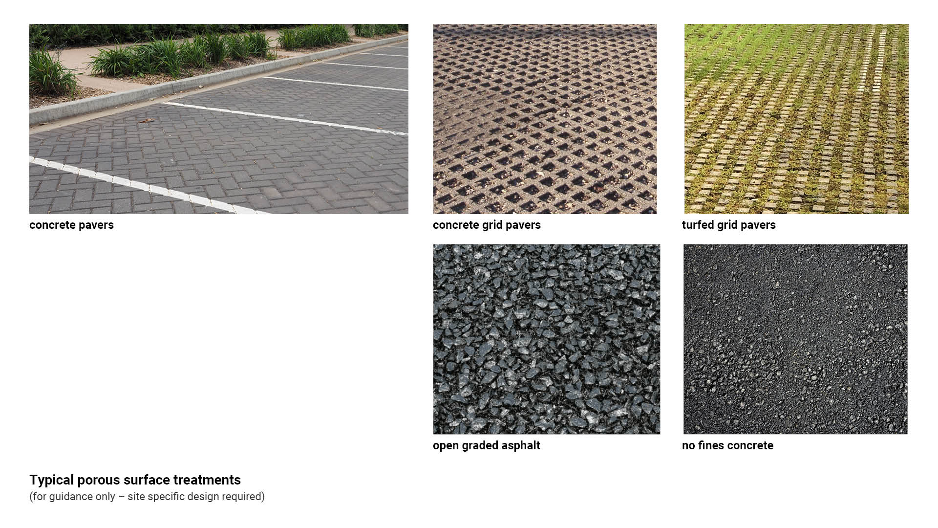
Porous surface treatments
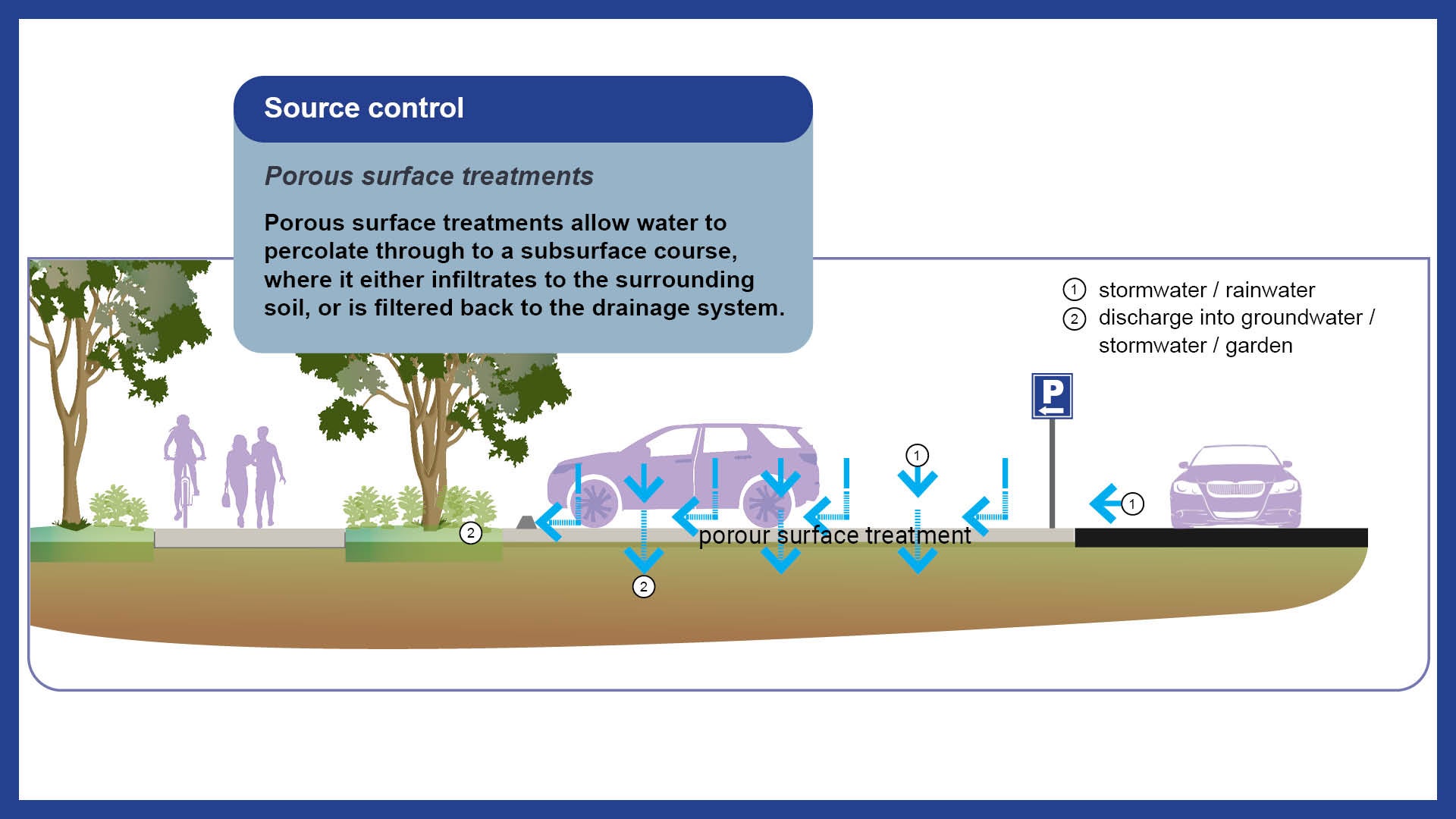
Porous surface treatments allow water to percolate through to a subsurface course, where it either infiltrates to the surrounding soil, or is filtered back to the drainage system.
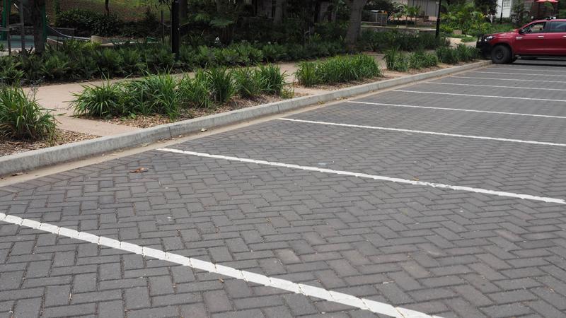
Porous surface treatments may be suitable for (but not limited to) use in carparks and pathways where it is important to capture the water to filter back into the ground and water the surrounding trees/gardens.
Provision
Porous surface treatments may come in the form of porous pavements (also known as permeable pavements). They are load bearing alternatives to impervious pavements which promote infiltration.
These solutions can perform primary and secondary treatment measures, including:
- Physical screening
- Rapid sedimentation
- Separation processes.
Function
The main functions of these treatments are:
- To treat stormwater which falls directly onto the surface treatment, such as pavements
- Where stormwater does not require any further treatment
- To achieve the same engineering requirements as conventional pavement
- For use in carparks
- Areas adjacent to mature/existing trees where surrounding hard surfaces do not allow adequate growing conditions.
Design
Porous paving products include the following:
- Porous concrete pavements (modular and monolithic) allow stormwater to filter through the pavement surface
- Pavements made from special asphalts that allow stormwater to filter through the pavement surface
- Concrete grid and turfed grid pavers allow stormwater to filter through voids in the concrete
- Plastic modular block pavement is not supported, as structural damage from tyre loads shortens the product life span.
See the following for further guidance:
- Table 11: Advantages and limitations for use of porous surface treatments
- Figure 15: Typical porous surface treatments.
Table 11: Advantages and limitations for use of porous surface treatments
Advantages | Limitations |
|
|
Figure 15: Typical porous surface treatments
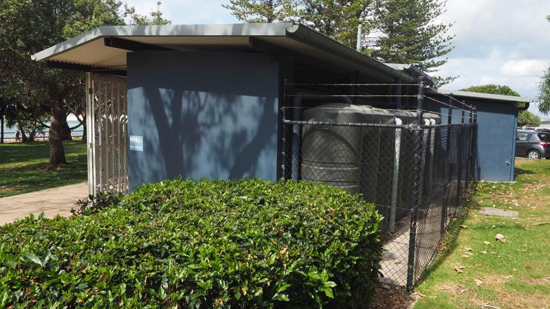
Rainwater tanks
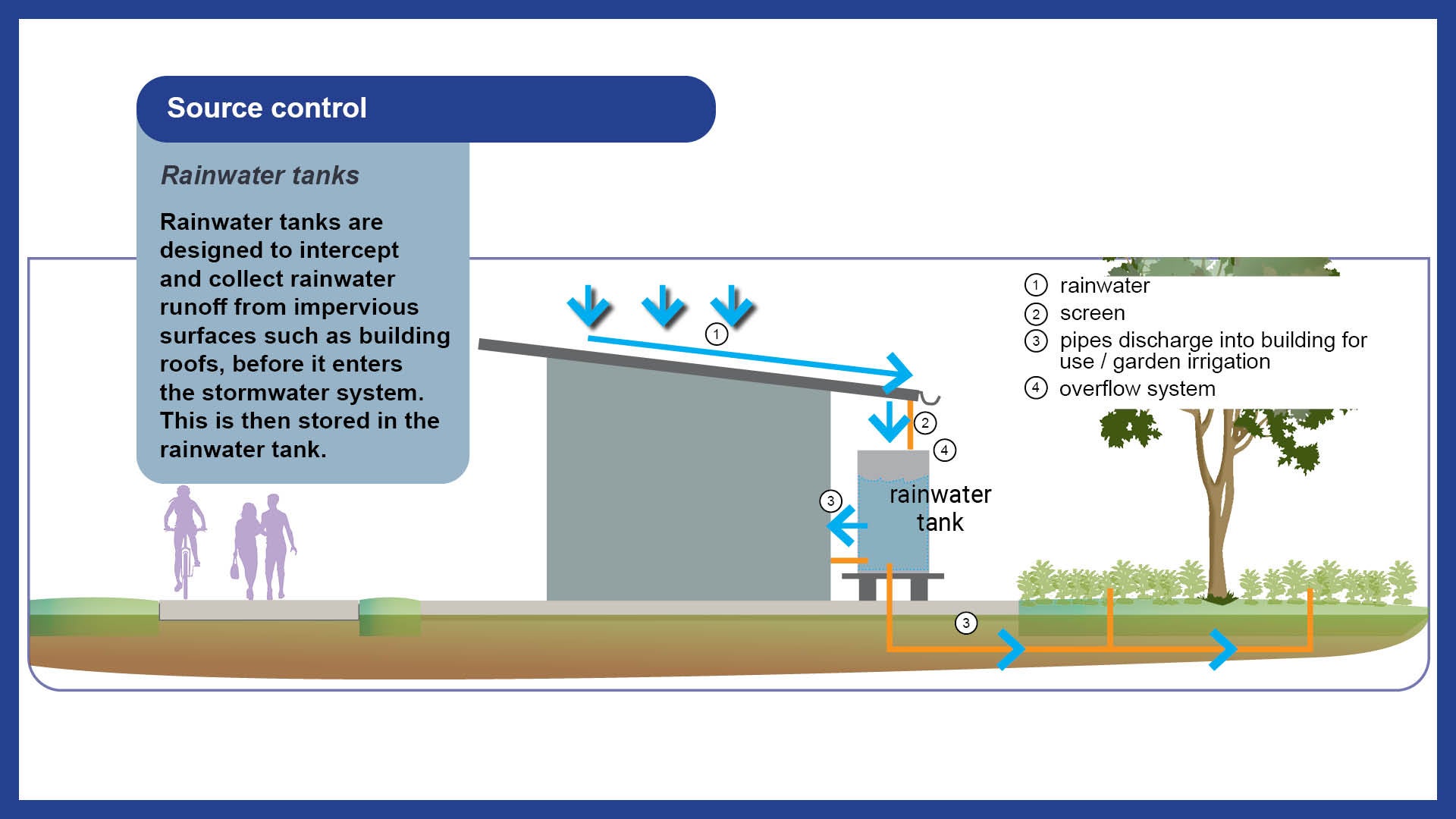
Rainwater tanks are designed to intercept and collect rainwater runoff from impervious surfaces such as building roofs, before it enters the stormwater system. This is then stored in the rainwater tank.
Rainwater tanks may be suitable for (but not limited to) use when attached to buildings to utilise the water captured from the roof. The captured water may be used in several ways; irrigation of nearby sportsfields and gardens, or to support the internal plumbing supply.
Provision
There are 2 types of rainwater tanks:
- Above ground
- Under ground.
Function
The main function for rainwater tanks is to reduce the demand/consumption of potable water.
Design
- Ensure mesh screen are installed on all access points to keep tank vermin free.
- Filter may be required if needed for consumption.
See Table 12: Advantages and limitations for use of rainwater tanks for further guidance
Table 12: Advantages and limitations for use of rainwater tanks
Advantages | Limitations |
|
|
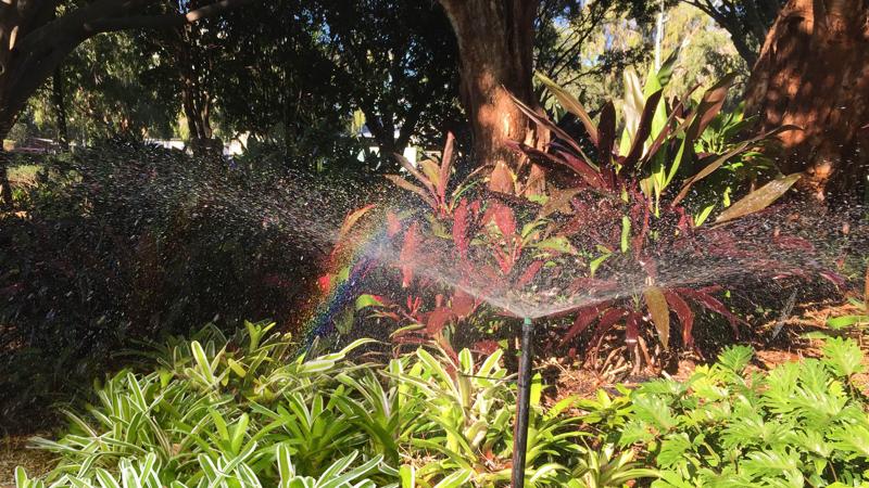
Passive irrigation
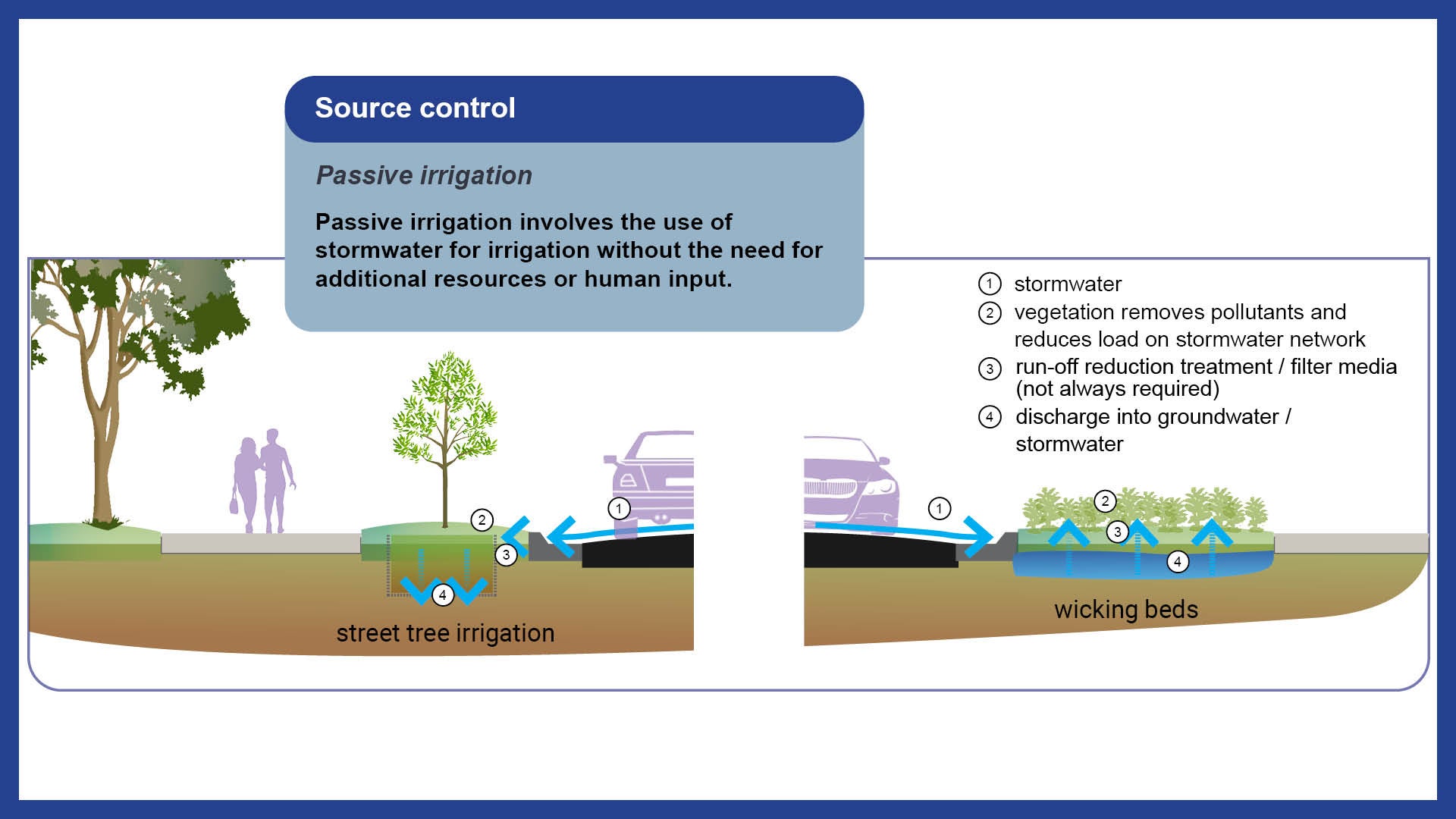
Passive irrigation involves the use of stormwater for irrigation without the need for additional resources or human input.
Storm watered street trees are appropriate for use (but not limited to) streetscapes and road verges.
There are two types of passive irrigation:
- Storm watered street trees
- Wicking beds/lawns.
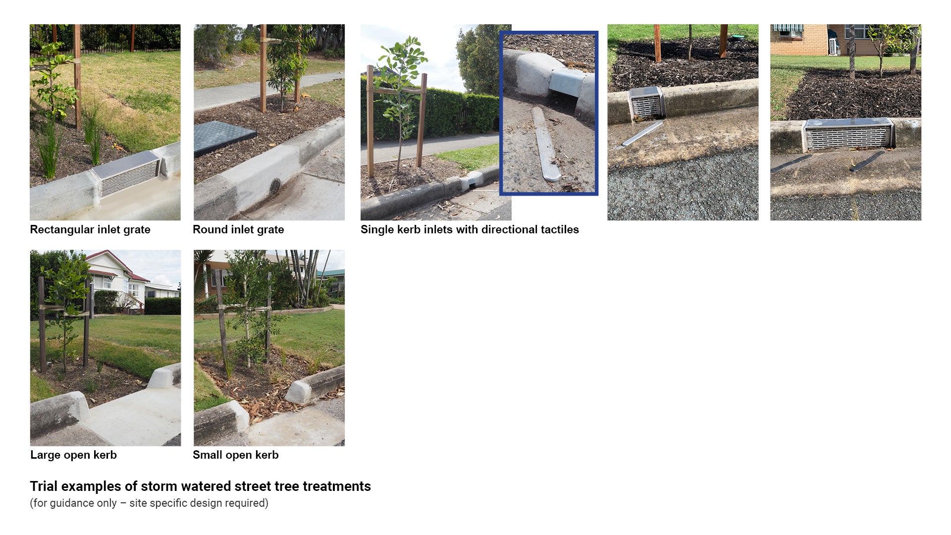
Storm watered street trees
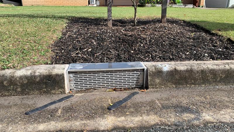
Storm watered street trees are appropriate for use (but not limited to) streetscapes and road verges.
Provision
- Typically, gravity is used to direct runoff from hard, impervious surfaces into tree pits or other vegetated areas. Most commonly, this water is directed into tree pits via kerb and channel inlets.
- Storm watered street trees are stand-alone systems, and are not suitable for stormwater treatment or conveyance.
Function
These systems can divert water at the surface, or through subsurface systems where plant roots can access the moisture.
See the following for further guidance:
- Table 13: Advantages and limitations for use of passive irrigation of street trees
- Figure 16: Example methods of laying pipe for passive irrigation of street trees
- Figure 17: Trial examples of passive irrigation of street tree treatments.
Table 13: Advantages and limitations for use of storm watered street trees
Advantages | Limitations |
|
|
Figure 16: Example methods of laying pipe for passive irrigation of street trees
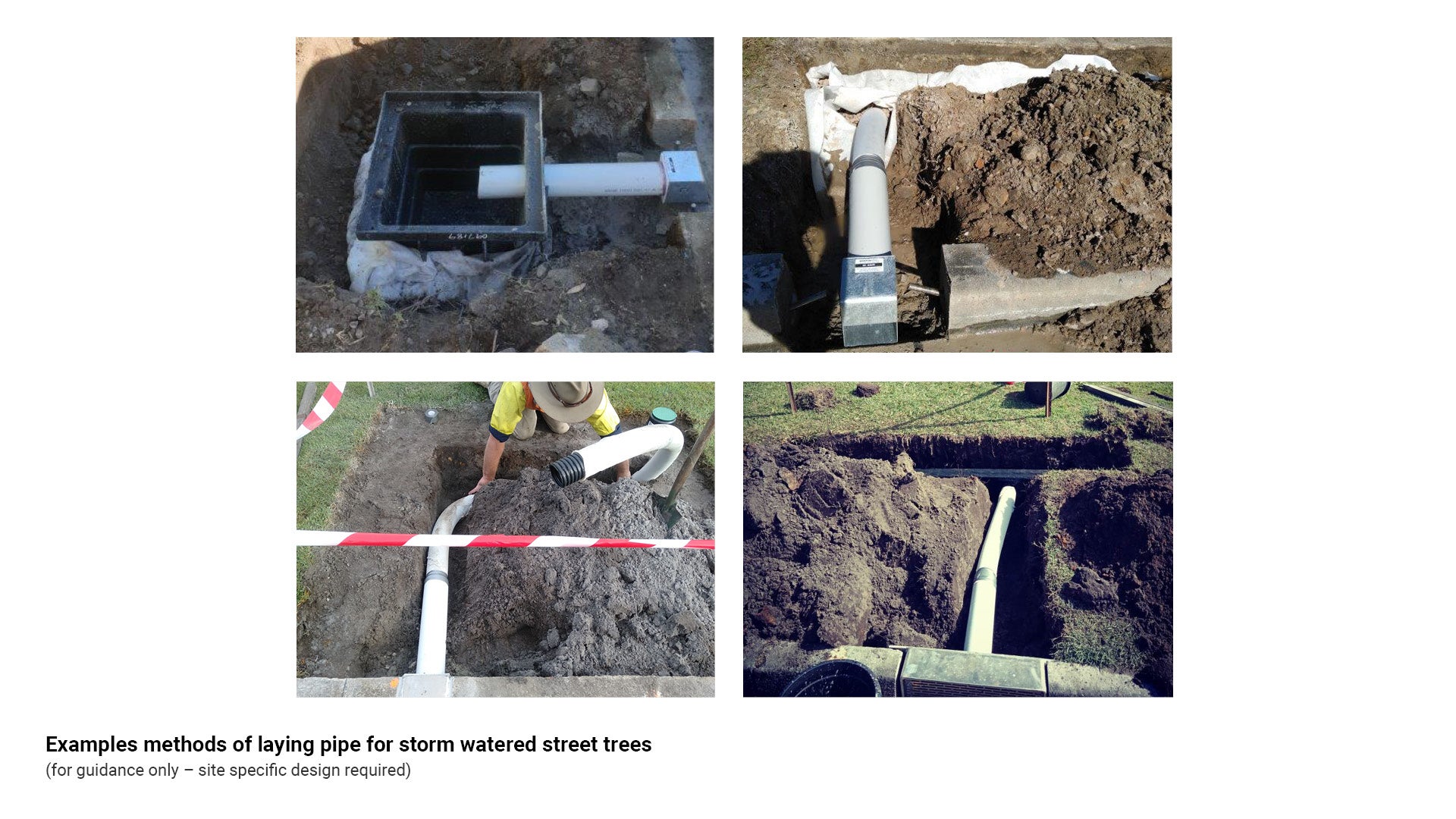
Figure 17: Trial examples of passive irrigation of street tree treatments
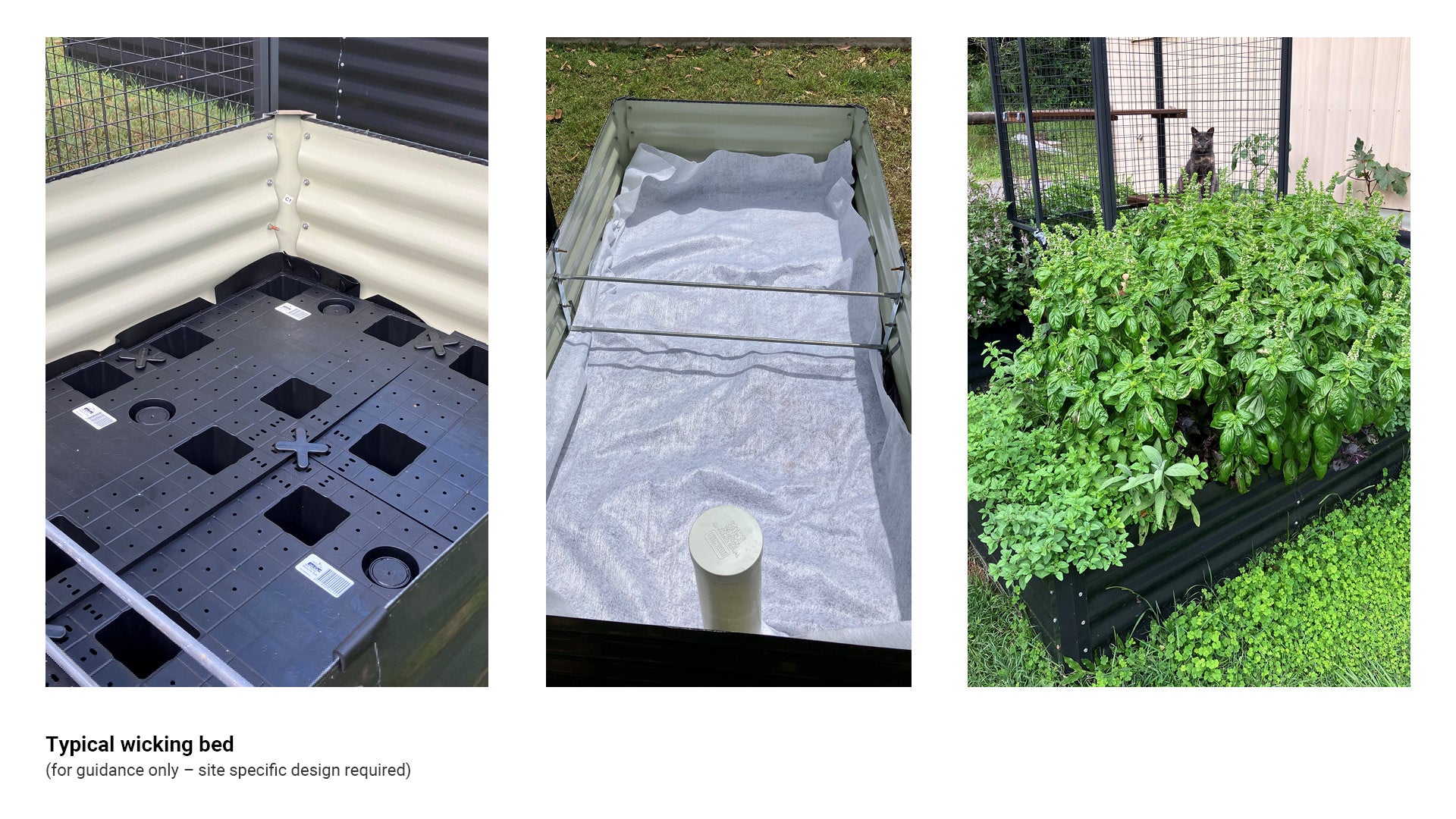
Wicking beds, wicking lawns
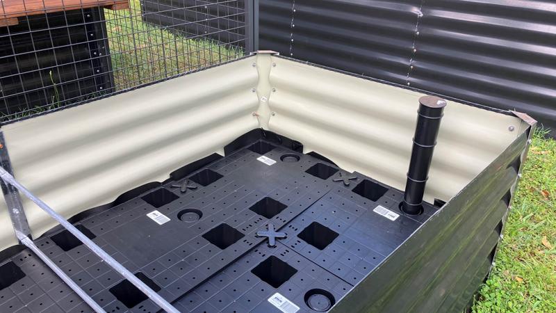
Wicking beds/lawns are appropriate for use (but not limited to) streetscapes and road verges.
Provision
Wicking beds/lawns are vegetated systems that are irrigated via subsurface water storage that uses capillary action to wick (draw up) into the soil profile.
Wicking beds are an emerging proprietary technology. In accordance with the policy direction of the Council's Stormwater Management Strategy the performance of such technology needs to be demonstrated and independently validated against the national standard. Local field testing is also required to demonstrate that such technology will not be a burden or liability for Council, prior to broad scale adoption as public realm infrastructure. When this has been demonstrated, if such technology is provided as contributed infrastructure, it must be provided with a sinking fund to manage and maintain the asset over its design life.
Function
- Wicking bed technology provides a storage area for locally harvested stormwater runoff
- The beds draw water from the storage area to the root zone by using the natural capillary action of soil
Design
- To provide vegetation with equal access to moisture, a wicking system needs to be located in a flat area
- Depth of soil/media is to be adequate to support the capillary action required for wicking and soil aeration.
See the following for further guidance:
- Table 14: Advantages and limitations for use of wicking beds/lawns
- Figure 18: Typical wicking beds/lawns.
Table 14: Advantages and limitations for use of wicking beds/lawns
Advantages | Limitations |
|
|
Figure 18: Typical wicking beds/lawns
Other systems
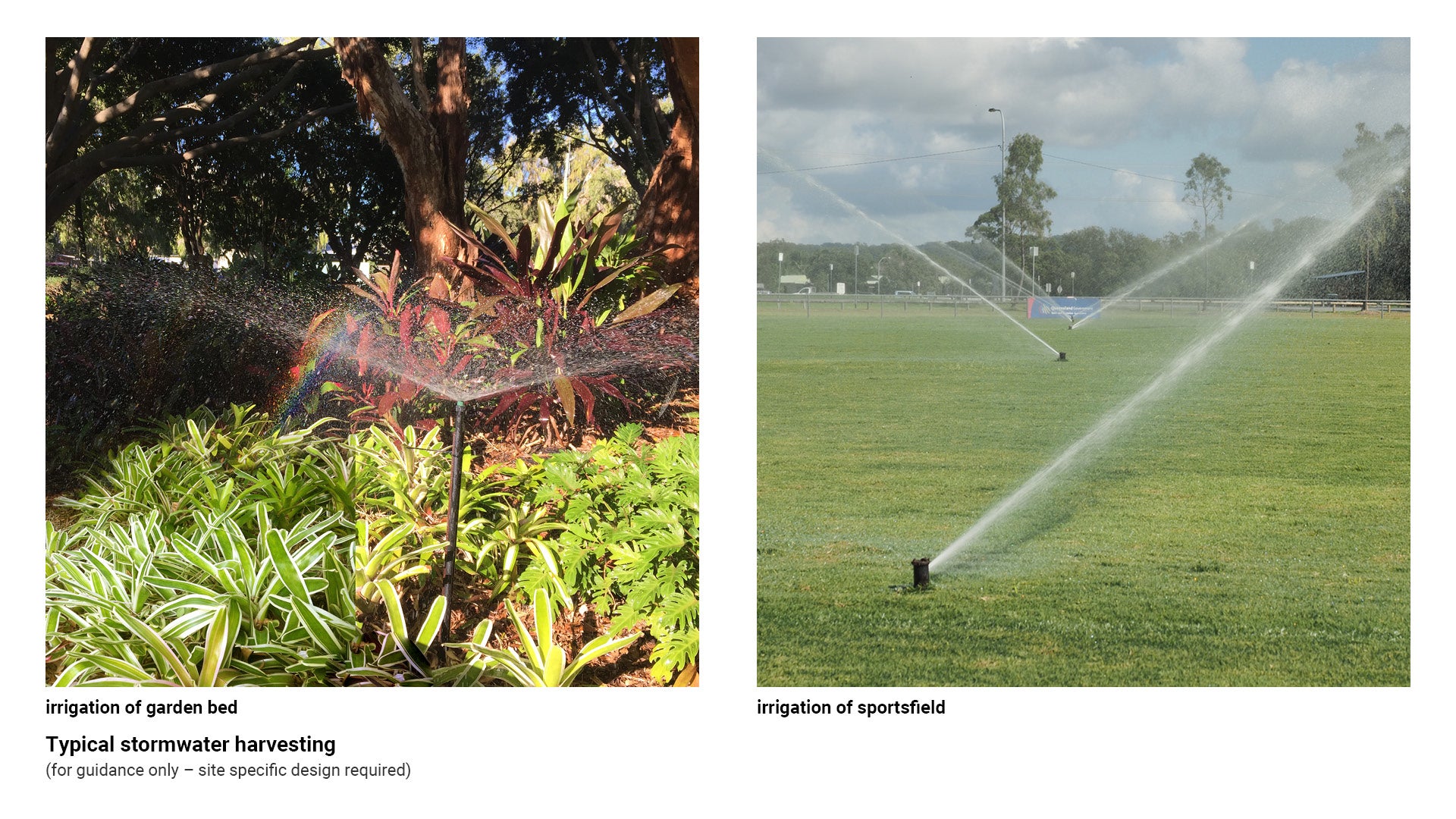
Stormwater harvesting and re-use
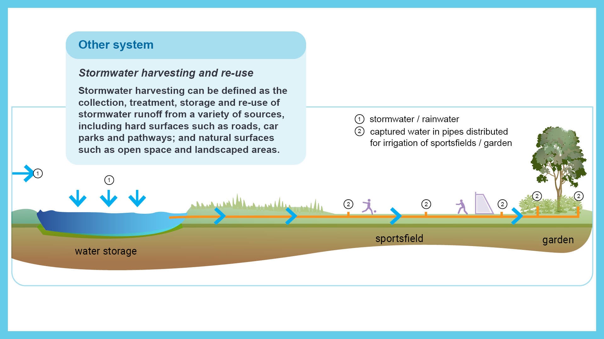
Stormwater harvesting can be defined as the collection, treatment, storage and re-use of stormwater runoff from a variety of sources, including hard surfaces such as roads, car parks and pathways; and natural surfaces such as open space and landscaped areas.
The stored stormwater may be used for (but not limited to) purposes such as garden and sportsfield irrigation.
Note: Stormwater harvesting and re-use must be successfully trialled on a small scale with supporting evidence documented, prior to implementation on a larger scale.
Provision
Above-ground (tanks or open bodies of water) or below-ground (reservoirs or aquifers) may be used for the storage of harvested stormwater.
Function
- Involves the collection, storage and eventual re-use of runoff from rain events.
- Stored stormwater may be used for garden and sportsfield irrigation, and other non-potable uses.
- In open space areas, this stored stormwater may be used to irrigate landscaped areas and sportsfields.
See the following for further guidance:
- Table 15: Advantages and limitations for use of stormwater harvesting
- Figure 19: Typical stormwater harvesting.
Table 15: Advantages and limitations for use of stormwater harvesting
Advantages | Limitations |
|
|
Figure 19: Typical stormwater harvesting
Infrastructure not supported by council
Table 16: Proprietary stormwater treatment devices
WSUD type | Application | Key considerations |
Media filtration devices Do NOT install |
|
|
Trash nets (drainage outlet nets) Do NOT install |
|
|
Sand filters Do NOT install |
|
|
Auxiliary embellishments
Auxiliary embellishments incorporated within open spaces ensure that public places are vibrant, inclusive, accessible, and meet the needs of people of all ages, abilities and backgrounds.
Open spaces are activated by the provision of facilities such as seats and shelters which welcome locals and visitors, providing a basis for maintaining safe environments through CPTED (Crime Prevention Through Environmental Design) principles.
See LIM Introduction and design principles for further guidance.
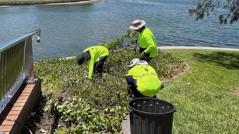
Maintenance: access tracks and service areas
Access tracks and service areas will be required to maintain WSUD components. Their requirements will vary dependent on the specific WSUD component. The following are examples of items that must be considered:
- maintenance access track:
- minimum width and gradient for service/maintenance vehicles (e.g. posi-track, weed harvesting vessel).
- suitable construction, possibly with reinforced materials.
- reinforced turf should be designed and laid to maintain optimal health.
- some may require construction of a concrete hardstand
- include provision for turning vehicles
- a lockable gate to restrict public access
- provision for stockpiling materials
- provision for maintenance activities.
All vegetated stormwater assets require a maintenance report as per Sunshine Coast Flooding and Stormwater Management Guideline requirements.
See the following for further guidance:
Drainage infrastructure
Note: This section should be read in conjunction with LIM Landscape drainage.
Further drainage infrastructure is documented in LIM Landscape drainage. This category refers to constructed items such as surface drainage, sub-surface drainage, side drains (swales and bio-swales), trench drains and grates, pipes and culverts, causeways and stepping stones, French drains.
Signage
Note: This section should be read in conjunction with LIM Signage suite.
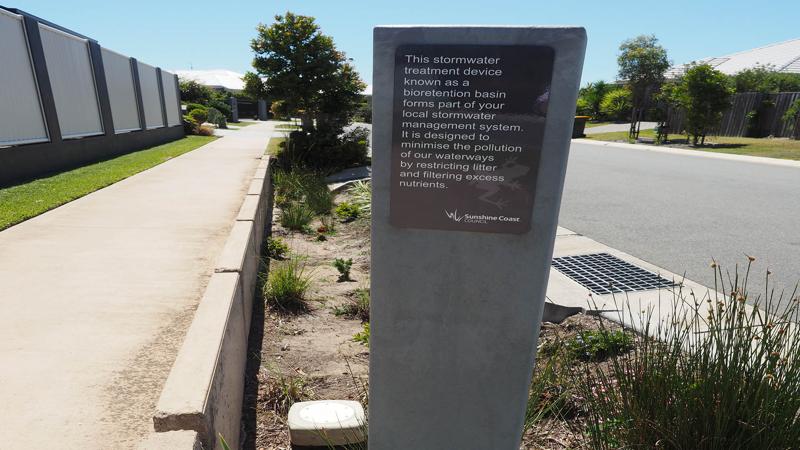
Educational signage can play an important role in creating an interactive design, engaging users in the space and educating them on WSUD functions.
Creating public awareness of WSUD functions can also be advantageous, particularly near residential areas. This can establish expectations around plant species selections, maintenance regimes and reduces the potential for unauthorised modifications. Some locations may benefit from education messaging regarding appropriate behaviours, such as 'Take your litter with you', 'Mind the wildlife', or 'No fishing'.
LIM Signage outlines various templates for Council Signage that may be used at WSUD locations.
Paths, trails and tracks
Note: This section should be read in conjunction with LIM Paths, trails and tracks.
Further pathway information is documented in LIM Paths, trails and tracks (PTT). It is important that equal access is considered in relation to the design of the pathway. Items such as the width (including the clearance area required beside a path), grade, selection of surface materials and target user groups, all are important considerations when planning and designing PTT.
PTT also includes design development information such as environmental management, benching and batters (greater than 1:4 slope is preferred for ease of maintenance), materials suitability, drainage, soil types and load rating. Surface types are discussed in further detail. Fire access trails are also documented.
Boardwalks and viewing platforms
Note: This section should be read in conjunction with LIM Boardwalks and viewing platforms.
LIM Boardwalks and viewing platforms should be referred to where PTTs require this infrastructure. These embellishments can provide elevated pedestrian access for viewing of waterbodies as part of successful co-location of open space functions. With good strategic design, selected locations may include signage as part of an educational promotion with the community.
Fences and gates
Note: This section should be read in conjunction with LIM Fences and gates.
Ramps and stairs
Note: This section should be read in conjunction with LIM Ramps and stairs.
Ramps and stairs should be referred to where PTTs require this infrastructure. This category also includes pedestrian infrastructure for recreation trails and low energy waterways, such as lakes and canals.
Vegetation management
Note: This section should be read in conjunction with LIM Trees - sensitive design (existing and new trees)
LIM Trees – sensitive design (existing and new trees) outlines various design solutions to protect trees. Methods discussed include elevated pathways and above grade pathways (no dig). Items such as artificial environments (for tree roots) and permeable surfaces are also documented. Passive irrigation of trees is documented as a benefit of directing road run-off and stormwater, away from the stormwater network.
Planting palette
Note: This section should be read in conjunction with LIM Planting palette.
LIM Planting palette contains a planting index that documents plants suitable for bio-retention systems (refer planting index table, in the section heading -sedges, reeds, rushes and other wetland edge plants).
Other
Note: This section should be read in conjunction with:
Guidance for the other relevant WSUD auxiliary embellishments is located in other categories of the LIM, including but not limited to the above list.
This component is currently in development