Paths, trails and tracks
Detailed design
Best practice guidance for the consideration of environmental and operational factors
Environmental management
This section is to be read in conjunction with:
Clearing vegetation
Clearing may be a necessary part of a path/trail/track (PTT) construction to create the path/trail route:
- Queensland vegetation protection law – Vegetation Management Act (Qld) 1999 (VMA) is the state-wide law regulating native vegetation clearing in Queensland.
- Path/trail clearing should have minimal impact on the areas surrounding the path/trail.
- It is an offence to cut down trees or clear or damage vegetation on council or State controlled land, including roadsides without approval.
- Specific construction treatments may be required to ensure adjacent trees are not damaged. Council (Parks and Gardens) and Council (Environmental Operations) must be contacted before any existing trees on council controlled land are pruned or cleared.
- All applicable permits shall be obtained prior to any construction commencing.
Clearing procedure
- If permitted under the relevant legislation, the removal of vegetation will include the clearing and disposal of all foliage, trunks, stumps and roots that occur on the PTT or within the overhead envelope. See Figure 11: Path/trail required offset widths for further guidance.
- Construction in natural areas may require greater clearance (during the construction phase) than the ultimate clearance envelope. This should be considered prior to seeking any necessary approvals.
- Material from clearing and pruning of native vegetation in natural areas should be distributed in natural areas adjacent to clearing, in areas devoid of vegetation (unless otherwise directed) or adjacent to the PTT to define the route. When doing this, the builder needs to be aware of the aesthetic environment into which cut material is being dumped to ensure cut vegetation does not become an unattractive part of the landscape. Disturbed areas should blend with the surrounding landscape when construction is finished.
- Material from non-native vegetation should not be disposed of in natural areas or areas of native vegetation.
- When removing vegetation, consideration needs to be given to the prevention of the spread of Myrtle Rust, Phellinus sp, and Phytophthora or the introduction of soil borne disease.
For further guidance and information on the clearing of vegetation, see LIM Environmental management of fauna and flora.
Flora and fauna
- All native flora and fauna in Queensland is protected under the Nature Conservation Act 1992 (NCA) and regulations. There are permit and approval requirements in relation to clearing vegetation and animal breeding places. An application for clearing native vegetation is required under the NCA.
- The Commonwealth Environmental Protection and Biodiversity Act 1999 may also apply if there is a matter of national environmental significance likely to be impacted by the clearing, or impact upon listed fauna.
- All applicable permits shall be obtained prior to any construction commencing.
Marine plants
- VMA does not apply to mangroves, grasses or other non-woody vegetation. Clearing these plants may require permits under other laws.
- There is legislative protection for clearing of riparian vegetation in various situations. Consider the Water Act 2000 and the Fisheries Act 1994.
- All marine plants in Queensland are protected under the Fisheries Act 1994 which is administered by the Department of Agriculture, Fisheries and Forestry (DAFF).
- Marine plants are regarded as any plant or plant material whether it is dead or alive, that is located in tidal water. There are permit and approval requirements in relation to disturbing marine plants.
See LIM Environmental management of fauna and flora for further guidance.
Erosion and sediment control
- PTT construction is to be carried out to avoid erosion, contamination, and silting construction is not to affect adjacent land use and creek and stream systems. Implement management measures to control these matters in accordance with Erosion and Sediment Control, International Erosion Control Association (IECA), 2008.
- Site topsoil is to be stockpiled on site for future use.
- All rubbish and deleterious materials will be removed from the stockpiles.
- Stockpiles are to be limited to 2.0 m wide by 1.0 m high and are to be contained with sediment control fences.
- Soils are not to be stockpiled directly under the tree canopy or against the trunk tissue of vegetation.
- Care should be taken to avoid removing any large trees or significant vegetation. Trees with a Diameter Breast Height (DBH) greater than 200 mm should not be removed and should be protected from impact (timber girdle or jute master matting) in accordance with AS 4970 – Protection of trees on development sites.
- Any disturbance of the ground profile by stump removal shall be backfilled and compacted (unless under the canopy of other trees) and left slightly above ground level to avoid future slumping.
See LIM Preliminaries for further guidance.
Benching and batters
Design – crown, outslope and inslope paths/trails
- Consider how the path/trail will fit into the landscape, the potential to minimise erosion and how to minimise impact on the environment. Also consider ease of construction and maintenance of the path/trail. Access will be required for construction vehicles and maintenance vehicles.
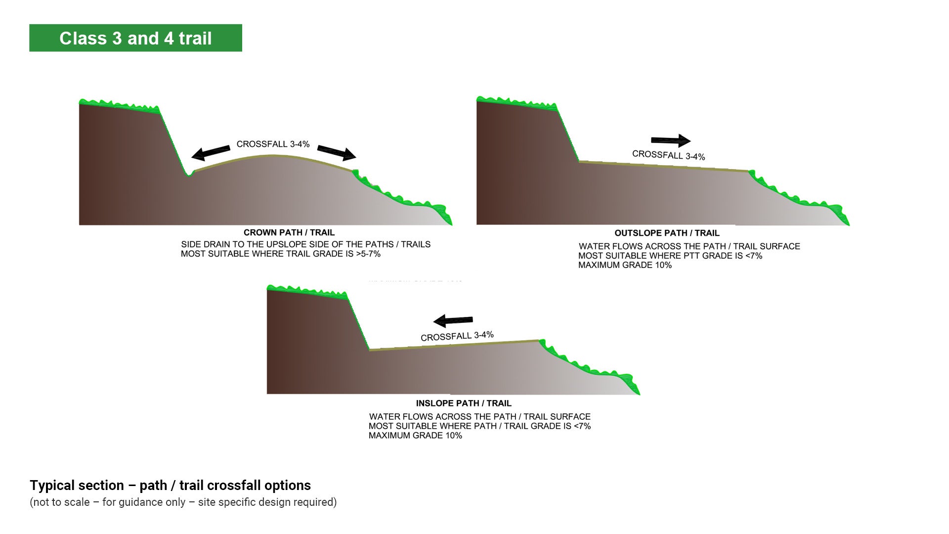
- A crowned path/trail together with a side drain on the upslope side of the path/trail will catch medium to high water runoff and provide protection for the path/trail pavement.
- An inslope or outslope path/trail allows water to flow across the track pavement and is best suited where the path/trail grade is less than 7% and water runoff is low. If the existing soil type is erosion prone, addition of gravel may be required.
- Cross fall for all slope types should be approximately of 3% to 4%.
See Figure 35: Typical section – path/trail crossfall options.
Figure 35: Typical section – path/trail crossfall options
Full bench (cut)
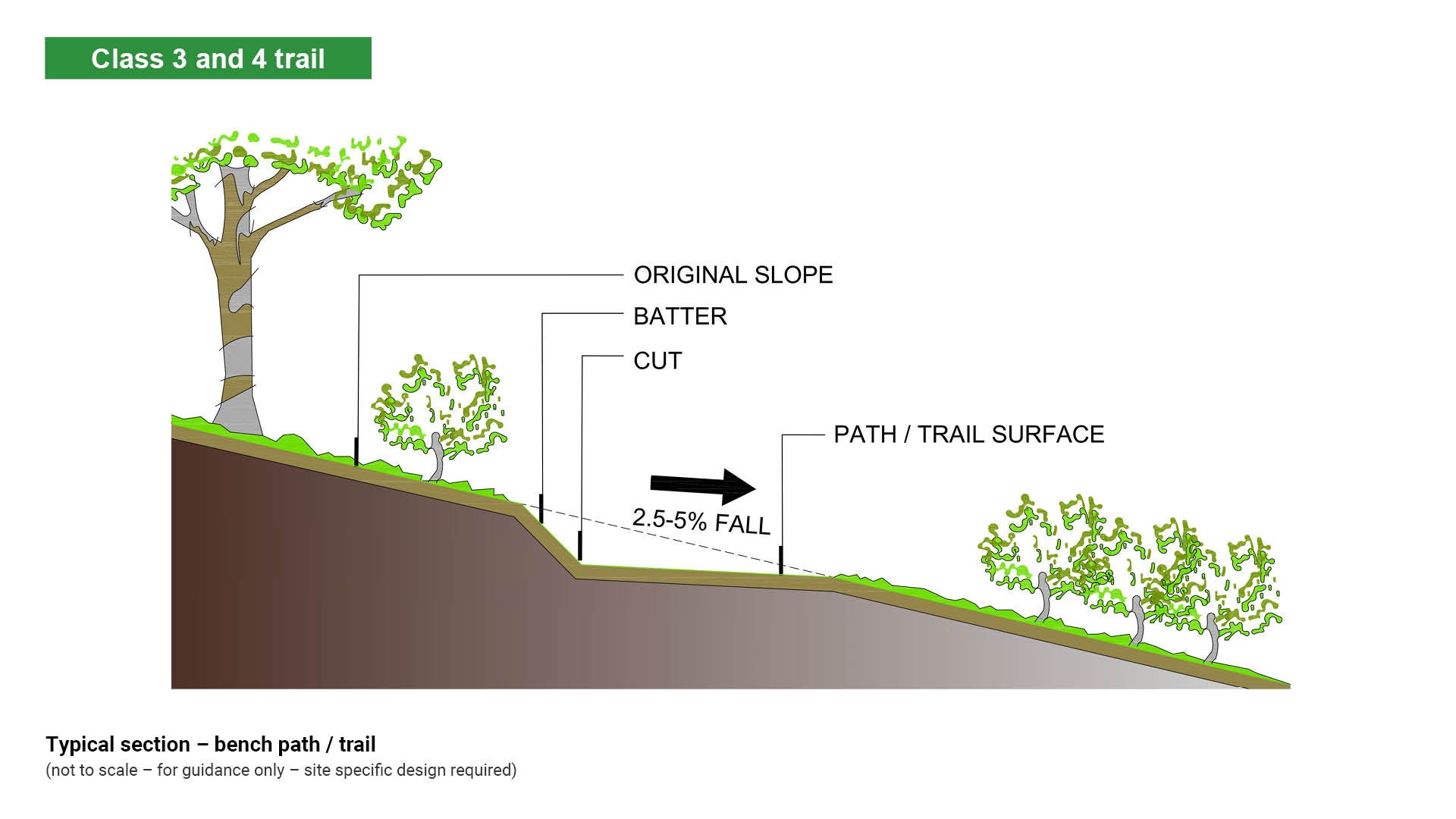
Path/trail construction may require excavation and earthworks to achieve accurate levels and profiles as a basis for the formation of a new path/trail. A level path/trail surface on a sloped surface may be achieved by full bench construction.
- Full bench tread involves excavating down and into the hillside. The resulting bench or flat surface forms the path / trail and puts the entire tread width on native soil, thereby maximising stability and minimising ongoing maintenance.
- On sloping ground, the path/trail tread should have a cross fall of 2.5% to 5% in the direction of the fall line. This is critical to assist in sheeting of water across the path/trail.
- For Class 1 walking paths/trails, the maximum cross fall is 2.5% in accordance with Australian Standards for Access and mobility.
- Accurate batter (back slope), crossfall and full bench cut minimise maintenance.
See Table 18: Maximum batter slope dependent upon soil type.
Table 18: Maximum batter slope dependent upon soil type
Soil type | Max batter slope ratio | Max batter slope % |
Sand | 1:4 | 25% |
Wet clay/loose gravel | 1:3 | 33% |
Loam/ordinary clay | 1:2.5 | 40% |
Compacted soil/gravel/rock | 1:2 | 50% |
Poor rock/shale/gravel | 1:1 | 100% |
Well bedded rock | 1:0 | vertical |
Siting guidelines
- Fill must not be placed in drainage areas or at the base of existing trees.
- Excavation will generally provide surplus material which can be used as fill to even out the path/trail. Leftover soil (spoil) should only be removed from the site if it cannot be used.
- Do not bury organic matter such as roots and branches in the fill.
- Set aside organic matter and spread onto the completed path/trail surface or onto batter slopes to enhance the natural appearance.
See Figure 36: Typical section – full bench path/trail.
Figure 36: Typical section – full bench path/trail
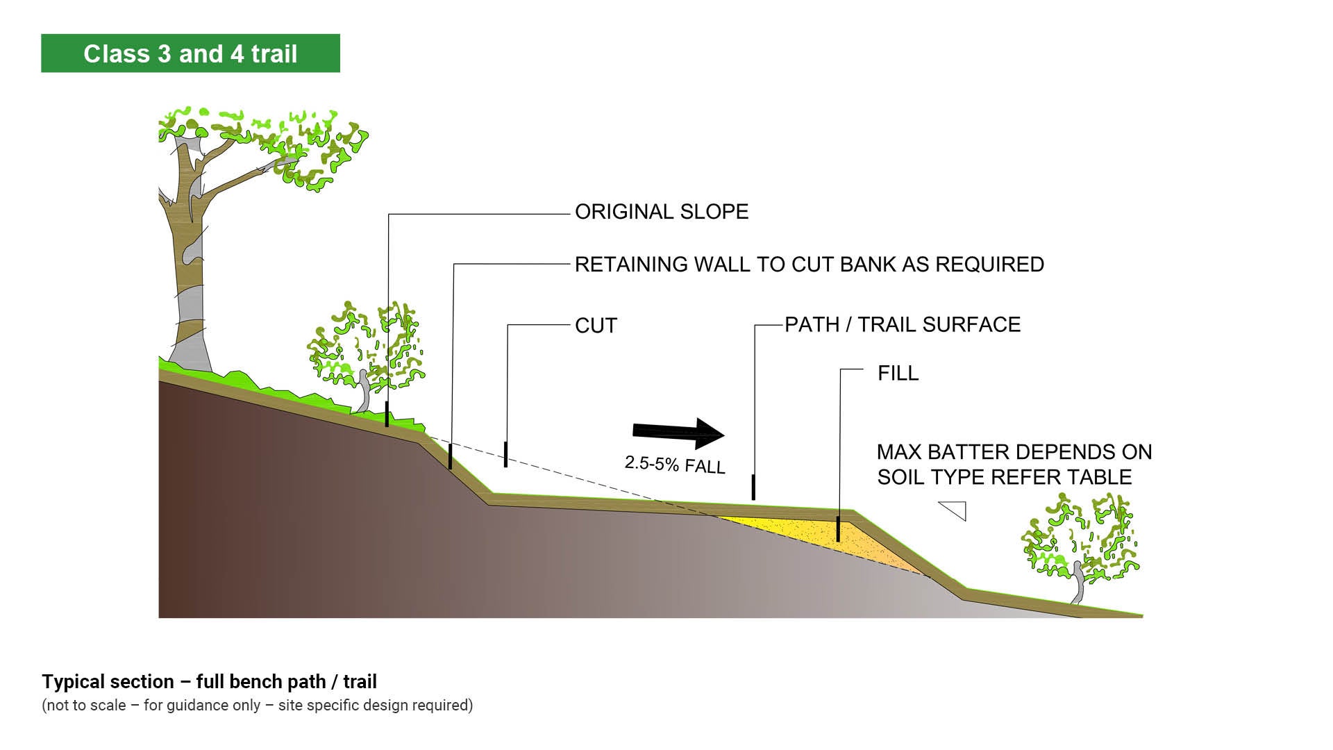
Partial bench (cut and fill)
Path/trail construction may require excavation and earthworks to achieve accurate levels and profiles as a basis for the formation of a new path/path. A level track surface on a sloped surface may be achieved by partial bench construction.
- Partial bench involves cutting into the uphill side slope and placing the fill on the downhill slope. This technique only works where the side slope is less than the maximum fill batter slope specified for the soil.
- Fill material must be compacted in layers no greater than 250 mm prior to compaction.
- Save any removed organic matter to be spread over the fill.
- On sloping ground, the path/trail tread should have a cross fall of 2.5% to 5% in the direction of the fall line. This is critical to assist in sheeting of water across the path/trail.
- For Class 1 walking paths/trails, the maximum cross fall is 2.5% in accordance with Australian Standards for Access and mobility.
See (above) Table 19: Maximum batter slope dependent upon soil type for further guidance.
Siting guidelines
- Fill must not be placed in drainage areas.
- Cut slopes should be made as steep as the soil type allows minimising impact on adjacent areas. Batters should be used on the back slope of benching.
- Batter stability is reliant on the angle of repose (the gradient of the slope at which the soil settles naturally) of the soil type.
See Figure 37: Typical section – partial bench path/trail.
Figure 37: Typical section – partial bench path/trail
Climbing turns
A climbing turn is built on the slope surface and where it turns, it climbs at the same rate as the slope. Climbing turns are incorporated into a path/trail alignment where it is necessary to gain elevation up a hill, in a relatively short distance.
- Climbing turns require less effort to build than switchbacks.
- Climbing turns require less excavation than switchbacks.
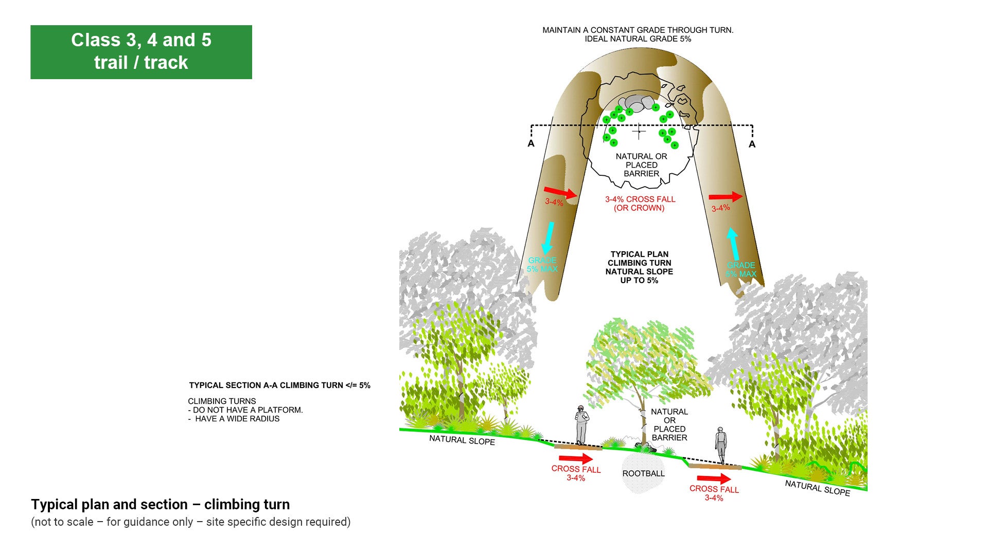
- Climbing turns are suitable on grades up to 5%.
- Climbing turns do not have constructed turning platforms and no fill is used.
- Barriers either natural or placed should be used between the arms of the turn to prevent shortcuts.
- Upper and lower path/trail cross-fall is aligned downhill.
- Avoid stacking turns up a hill by using the full available width of the hill.
- Always seek the flattest site to construct a climbing turn.
- Minimise turns in path/trail planning.
See the following:
- Figure 38: Climbing turns
- Figure 39: Typical plan and section – climbing turn.
Figure 38: Climbing turns
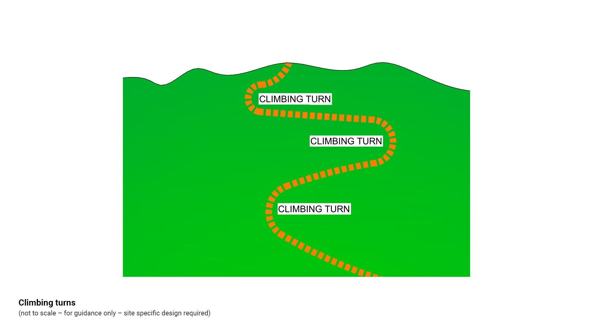
Figure 39: Typical plan and section – climbing turn
Switchback
Switchbacks, sometimes called hairpin bends, are a tight turn for climbing a steep hill. The term switchback is also used as a generic term to describe how a path/trail climbs a slope.
- Look for natural platforms when selecting possible switchback locations.
- The upper approach and upper half of the turn platform are excavated from the slope.
- Part of the lower approach and the lower half of the turn platform are constructed on fill.
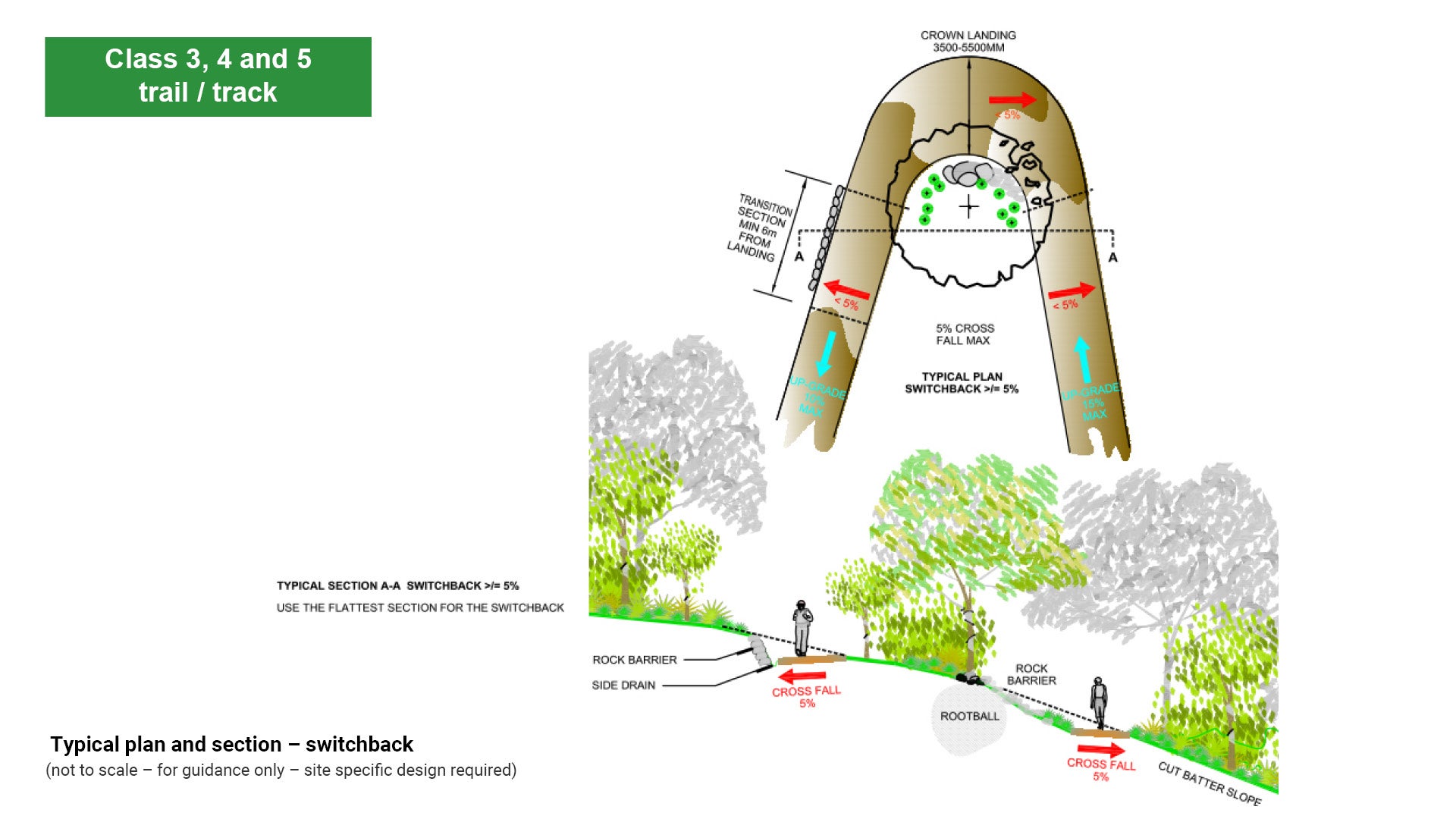
- Use a switchback on grades greater than 5% and less than 15%.
- They should be free flowing and gentle with a radius of at least 10 m.
- Maintain a constant grade and radius through the section.
- Switchbacks should have a smooth turning radius (1.5 m-3.0 m) and barriers (natural if possible) between the arms of the turn to prevent shortcuts.
- Upper path/trail cross-fall is aligned uphill (with side drain) and lower path/trail cross-fall is aligned downhill.
- Switchbacks may require appropriate retaining structures to hold the fill in place and to shore up the turning platform. The retaining wall will also act as a barrier to prevent short cuts. Minimise turns in path/trail planning.
- Avoid stacking turns up a hill by using the full available width of the hill.
See the following:
- Figure 40: Switchbacks
- Figure 41: Typical plan and section – switchback.
Figure 40: Switchbacks
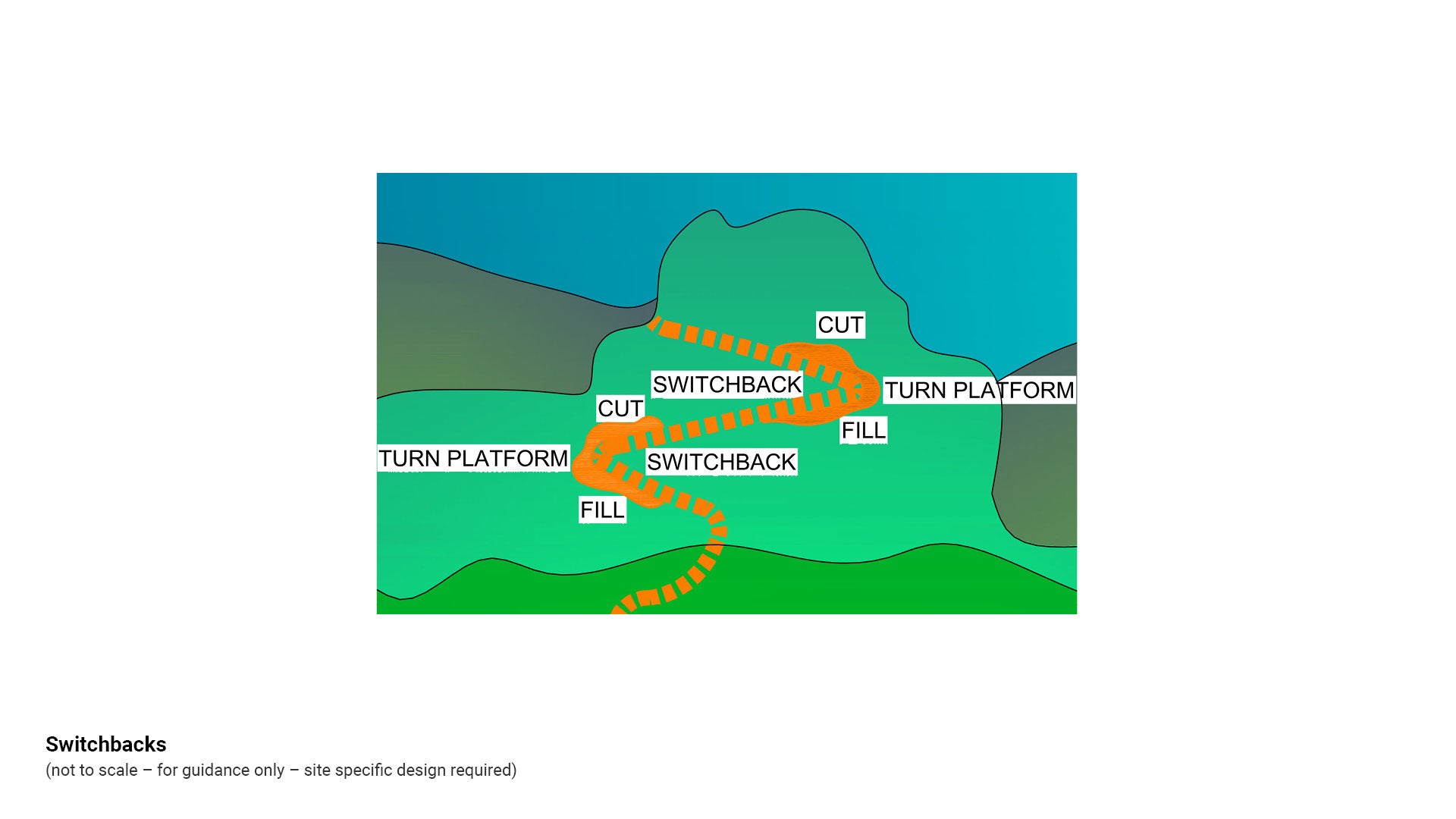
Figure 41: Typical plan and section – switchback.
Materials suitability
Path and trail surface design should balance aesthetics, accessibility, durability, and maintenance requirements while considering environmental context and practical access for construction and upkeep.
Aesthetics and character
- Consider the aesthetic appearance of the surface material adopted within the context of the character of the path/trail surroundings.
- If a firm hard surface is required to comply with equal access requirements, can the visual effect be softened and integrated with its surroundings by the use of different colours and/or surface treatments?
- Plain white concrete is cost effective for installation and maintenance however it can produce glare in full sun locations. This can create hazards for persons with vision impairment.
- Innovative surface results can be achieved in a cost effective manner e.g. locally sourced leaves pressed into a trowelled concrete surface prior to hardening. The result is a natural, embellished finish which is pleasing aesthetically and enhances the natural character of an area.
Maintenance
- Consider the long term maintenance of the path/trail surface selected. Natural surfaced paths/trails are cost effective to construct however they require a consistent approach to inspection and maintenance to maintain the quality of installation. They are also subject to storm damage which requires extra inspection and maintenance regimes.
- Exotic and imported materials are discouraged as they may incur long lead times for materials supply and high replacement cost for damaged sections and for future upgrade. If exotic or imported materials are used, make provision for extra material which can be stored for critical repairs.
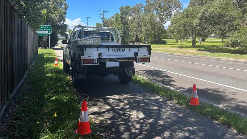
Remote area access
Consider construction access to remote areas for:
- materials supply vehicles.
- construction machinery and equipment.
- materials storage during construction.
- work force parking, access and site set-up facilities.
- evacuation from site and first aid for emergencies such as snake bite, spider bite and broken limbs.
Consider access to remote areas for path/trail user groups, council inspection and maintenance and emergency services:
- Maintenance vehicle path/trail crossover and parking.
- User group remote path/trail head facilities.
See LIM Fences and gates.
- Connectivity and crossover with existing paths/trails to accommodate shared use of existing embellishments such as seating, picnic tables and benches, shelters, barbecues and toilets and signage. See relevant LIM categories for further guidance.
Drainage
A wide range of design solutions is available to accommodate varying environmental conditions and pathway classifications.
See LIM Landscape drainage for drainage solutions such as:
- surface drainage.
- sub-surface drainage.
- side drains (swales and bio-swales).
- trench drains and grates.
- pipes and culverts.
- causeways and stepping stones.
- French drains.
Soil types
Design of a path/trail surface treatment is based upon natural soil type. Soil is characterised by its structure which in turn is determined by particle size.
See Table 19: Field test to determine soil type.
Table 19: Field test to determine soil type
Soil type | Soil description | Characteristics |
1. Clay 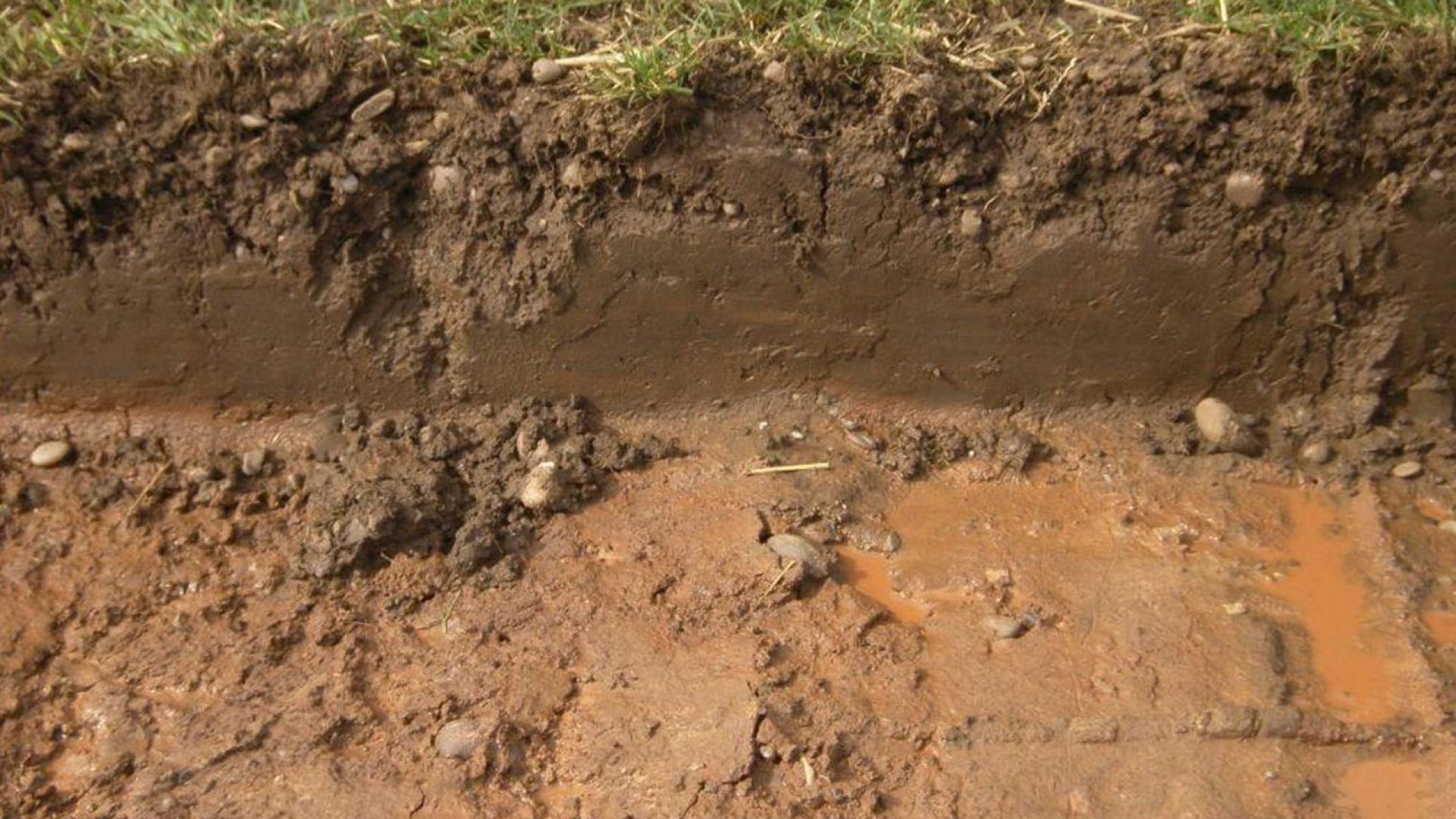 | Clay consists of small particles. | moist clay – easily forms into a ball and leaves a stain in the palm of your hand. Is highly plastic (bends and flexes) dry clay – is very hard and almost impossible to break with your hand. |
2. Silty soil 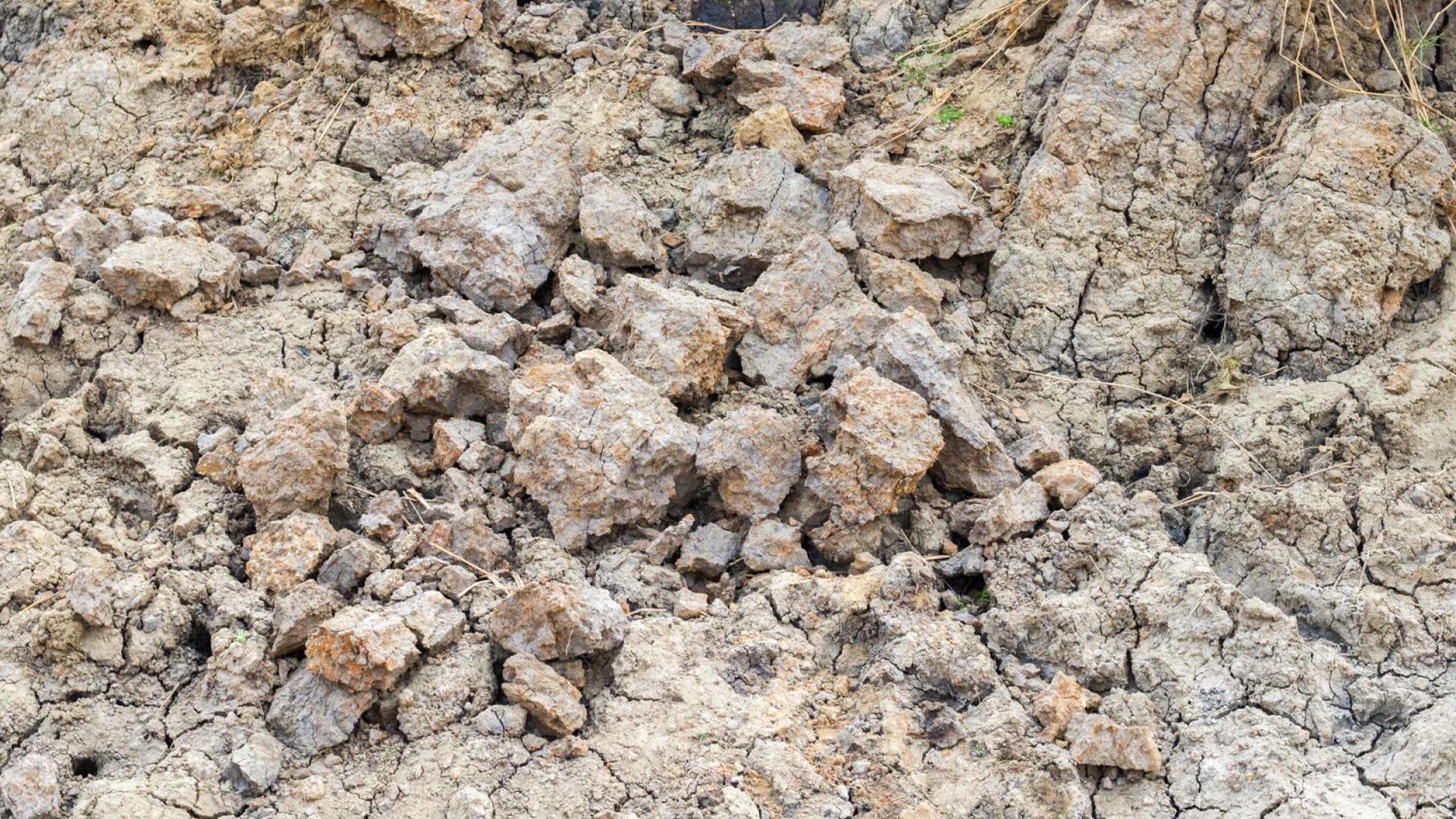 | Silty soil consists of particles which vary between clay and very fine sand. | Place a handful of soil (sufficiently wet to be almost sticky) in the open palm of your hand. Tap bottom of your hand with the other hand. If the sample is silt, water will appear at the surface giving a shiny appearance and it will disappear if the sample is squeezed or manipulated. When the sample is manipulated it tends to dilate and draw water back into it. moist silt – feels smooth and sticky but falls apart and does not leave much of a stain on your hand. dry silt – feels like flour, smooth and powdery. |
3. Sandy soil 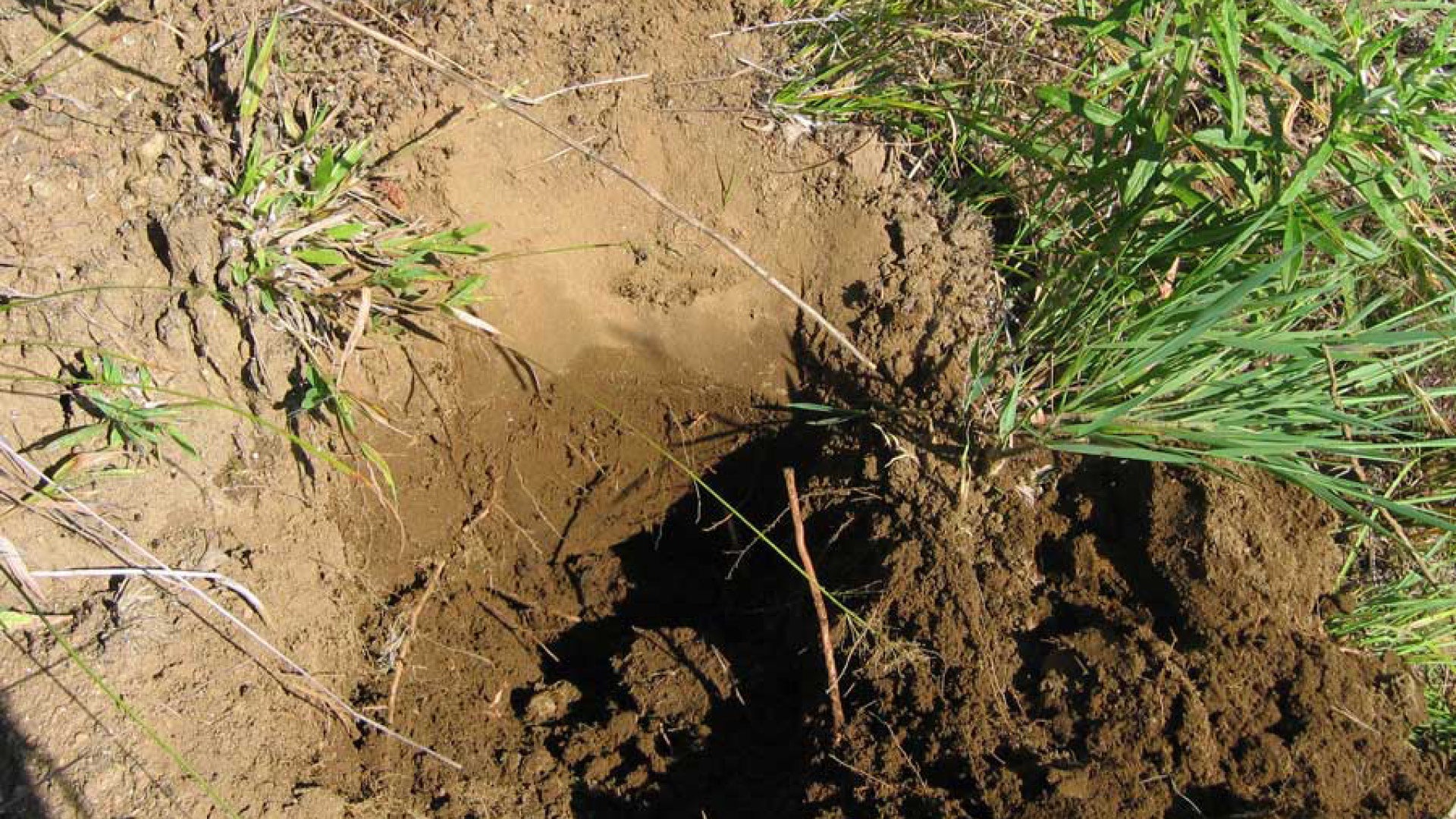 | Sand soil consists of either rock fragments or single materials of various shapes and sizes. | moist sand – when squeezed together in the palm of your hand will form a ball which will break apart easily and not leave a stain on your hand. dry sand – feels rough and will not hold together. You can see individual particles of sand. |
4. Loam soil  | Loam soils are a combination of all three particle types in which no particle type is dominant. These soils are good to work with, having reasonable drainage and holding together well. | wet loam – forms a ball when squeezed together in the palm of your hand. It is neither too gritty nor too sticky. |
Source: Environmental Protection Agency Appendix 6A Soil Identification in the Field.
Sub-grade (native soil) treatment
Following determination of soil type, establish the load carrying characteristics of the native soil. A soil test will determine:
- the sub-grade strength expressed as California Bearing Ratio (CBR). CBR is a penetration test developed by the California Department of Transportation. CBR is a measure of the strength of the sub-grade and is a recognised international engineering Standard.
- load support capabilities of the sub-grade.
- prevailing ground water conditions at the site.
See Table 20: Sub-grade treatment based on soil type.
Table 20: Sub-grade treatment based on soil type
Soil description | Path/trail sub-base compaction treatment |
Wet soft organic soil/soft marine sediment – CBR<3% | Drain the area. Use imported fill to form sub base. Path/trail pavement to match sub-base material, or provide a boardwalk. Avoid this soil type where possible. Select an alternate route. |
Soft clay/silt – CBR 3%-5% | Compact sub grade. Use 75 mm - 150 mm compacted aggregate pavement on geo-textile. Drain area and allow it to dry out. |
Firm clay/silt – CBR 5%-7% | Compact sub grade. Use 75 mm - 100 mm compacted aggregate pavement. Bare or grass surface may be adequate in low use areas. |
Compacted clay – CBR 7%+ | Use 50 mm -75 mm compacted aggregate. Bare or grass surface may be adequate in low use areas. |
Sub-base treatment (imported material)
Following establishment of the soil type, CBR and site conditions, (including the presence of existing trees), material, compaction treatment and thickness of the sub-base can be determined. The CBR of the sub-grade determines the sub-base construction thickness.
Sub-grade treatment needs to be mindful of and appropriate for existing trees. Alternatives options such as raised designs or path re-alignment may be required where conflicts cannot be resolved.
See Table 21: Sub-base thickness based on CBR.
Table 21: Sub-base thickness based on CBR
Strength category | CBR % | Sub-base (mm) |
Poor | 2% | 385 mm |
3% | 270 mm | |
4% | 210 mm | |
Moderate | 5% | 165 mm |
˃5% | 150 mm | |
High | 10% | 150 mm |
Source: Department of Infrastructure, Transport, Regional Development and Local Government – User Guide to bicycle and shared path selection – using whole of life costing.
Pavement design
The pavement and surfacing type selected can be designed for a wide range of environments to ensure an acceptable service life. Pavement compaction varies according to the pavement material selected.
Design load rating is determined by the use requirement of the path/trail (pedestrian, vehicular or multi-use). Pavement compaction is in turn dependent upon the design load requirement for the path/trail.
Load rating
This section outlines design considerations for pavements and surfaces to accommodate both recreational users and vehicle loads, ensuring compliance with safety standards and structural performance requirements.
Design for recreational user load
- Surface treatments for recreational paths/trails should be stable, firm, even and provide slip resistance in accordance with AS/NZS 3661.2 – Slip Resistance of pedestrian surfaces – Guide to the reduction of slip hazards. Identified user groups, together with factors such as existing topography, recreational opportunity and expected volume of users will indicate the characteristics of the surface treatment required.
- Rigid (concrete), flexible (asphalt), unsealed (gravels) or stabilised gravel pavements are designed for thickness and compaction to suit the existing soil load bearing characteristics as determined by soil test results.
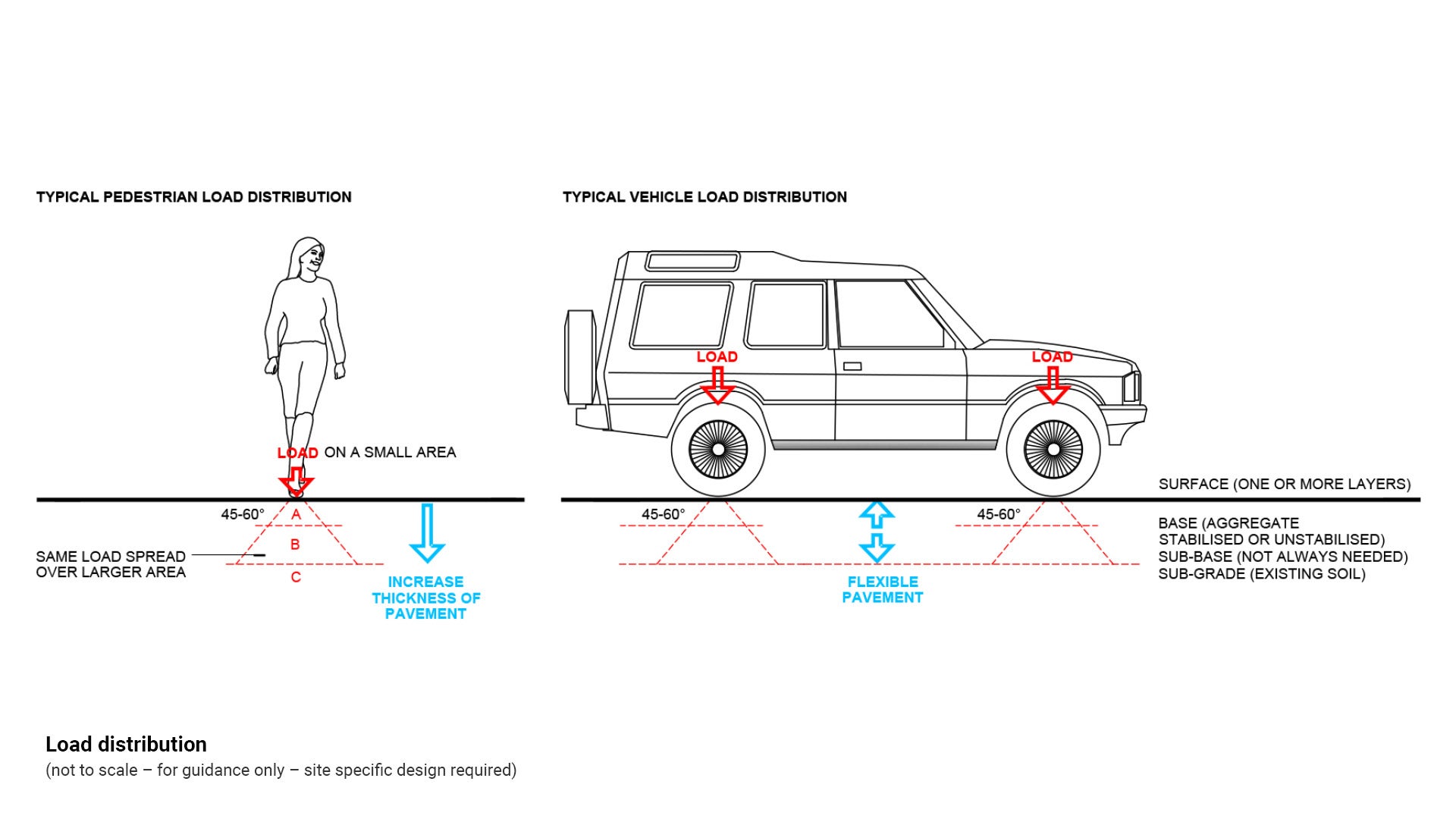
Design for vehicle load
- The pavement is required to support the wheel loads from vehicles which will have access over it. The first step in designing pavement thickness for a vehicle to cross over is to determine the loading that the pavement will be subjected to.
- Vehicle types may include local laws (quad bikes), maintenance vehicles (truck with chipper), construction vehicles and machinery (truck plus excavator or crane) and emergency vehicles (fire, ambulance, SES).
- See Council Standard drawings
- RS–051 Driveways: Heavy duty vehicle crossing
- RS–050 Driveways: Residential driveway (breakout type)
- RS–056 Driveways: Vehicle crossing - rural driveway.
See Figure 42: Load distribution.
Figure 42: Load distribution
This component is currently in development