Paths, trails and tracks

Surface materials
Best practice guidance for the selection and construction of surface materials
Colour selection and construction tolerances
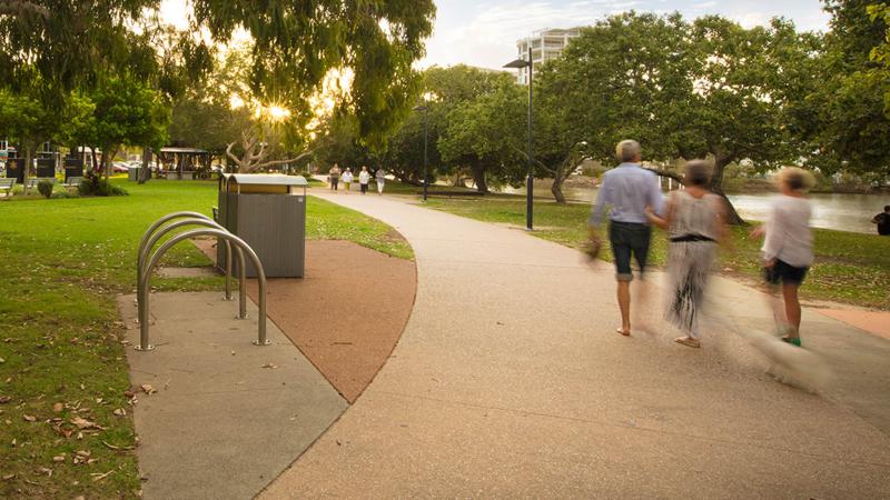
Surface design for paths and trails must comply with construction tolerances and consider accessibility, glare, heat, and visual contrast to ensure safety and usability for all users, including those with mobility or vision impairments.
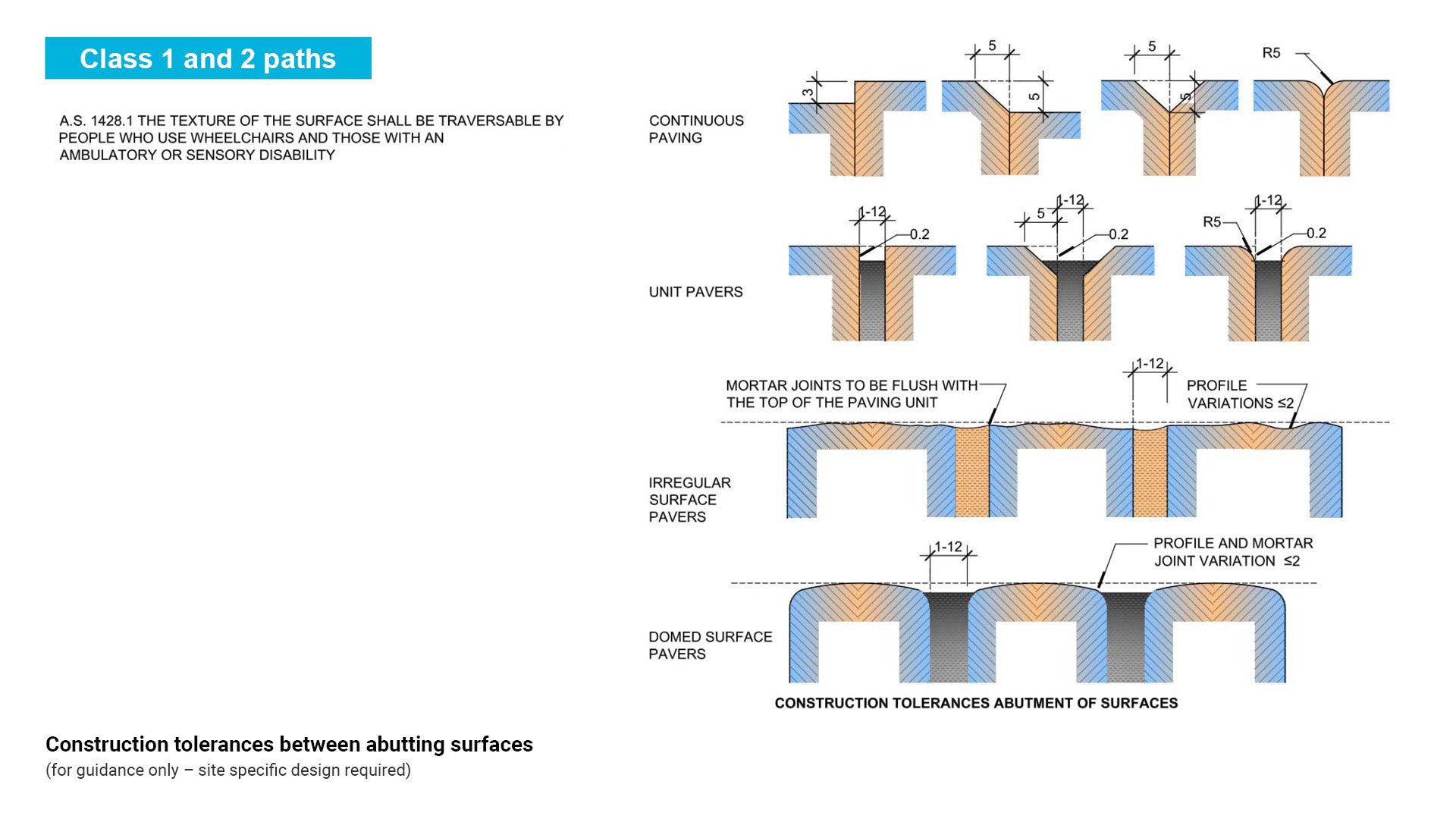
The following Figure 43: Construction tolerances between abutting surfaces, shows allowable construction surface tolerances for continuous paving and unit pavers. A smooth surface helps people who use wheelchairs and people with ambulatory or sensory disabilities. People who are unsteady on their feet can trip over small projections or uneven surfaces. The following are situations where care is required to design an equal access path/trail which is able to be used by everyone:
- ensure that public art such as inlaid mosaic tiles are incorporated into paths of travel in such a way that they comply with construction tolerances.
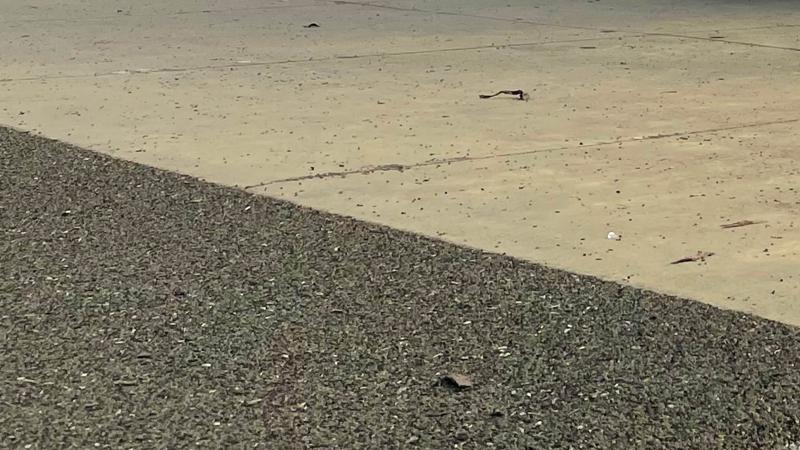
- selection of coloured path treatments should consider heat radiation from dark surfaces and luminance contrast, in prevailing conditions. Some people with low vision encounter difficulty coping with surfaces which create glare. Coloured surfaces should not blend into the background but should provide edge definition or contrast to the surfaces abutting the path. Consider that contrast and definition make it easier for people with low vision to negotiate through an environment.
- Austroads Guide to Road Design Part 6A: Paths for walking and cycling provide direction on desirable selection of path colour and surface tolerance, such as:
- Concrete and other light coloured surfaces are preferred in hot climates as they radiate less heat.
- Protrusions as low as 6.0 mm can cause people to stumble and fall.
See the following for further guidance:
- Figure 43: Construction tolerances between abutting surfaces
- Table 23: Summary surface types.
Figure 43: Construction tolerances between abutting surfaces
Surface materials – summary table
The following table outlines the advantages and disadvantages of various surface materials.
- Design life: the lifespan for which an embellishment is expected to function, without major repair.
- Useful life: the period during which an embellishment is expected to be usable. Used in calculating depreciation of an object, and may or may not correspond to an embellishment’s actual physical life.
Table 22: Summary surface types
Class (AS 2156.1) /surface type/ typical users | Advantages | Disadvantages | Design life/useful life |
  Surface type: Sealed surface – concrete Typical users:  |
|
| Design life: lifespan of 40 years but generally maintenance free for 15 years Useful life: 50 years |
Surface type: Sealed surface – brick or clay paver Typical users: |
|
| Design life: generally, 30 years (concrete). Useful life: 20 years |
Surface type: Sealed surface – Asphalt including coloured asphalt, chip-seal and spray seal Typical users: |
|
| Design life: Lifespan of 20 years if properly constructed and maintained. Useful life: 30 years |
  Surface type: Sealed surface – Stabilised gravel Typical users:  |
|
| Design life: 10 years Useful life: 10 years |
Surface type: Sealed surface – Recycled material or composite fibre Typical users:  |
|
| Design life: New product – limited information. Useful life: 10 years |
Surface type: Sealed surface – Modular concrete system Typical users:   Management vehicles (if product is designed for use). |
|
| Design life: Lifespan of 40 years but generally maintenance free for 15 years Useful life: 50 years |
Surface type: Unsealed surface –compacted path/trail surface at grade Typical users:  Management vehicles (if product is designed for use). |
|
| Design life: Maintenance required after 6–12 months. Lifespan of 5 years Useful life: 10 years |
 Surface type: Unsealed surface – unmodified natural path/trail granular surface Typical users:  Management vehicles (if product is designed for use). |
|
| Design life: N/A Useful life: 10 years |
Sealed Surface – concrete
Concrete comprises a high strength cement bound layer over a lower strength granular sub-base. Concrete paths can be used wherever sealed, all-weather and easily accessible paths are required for pedestrians and cyclists. Concrete paths are generally Class 1 and Class 2.
Concrete surfaces
- Are generally accessible and suitable for wheelchairs, mobility scooters and crutches.
- Smaller equipment is required for construction.
- Concrete surfaces can be coloured to improve aesthetic appeal.
- They should be sealed to prevent colour fade. Use a slip resistant sealant product suitable for pedestrian paths. See to HB 197: An introductory guide to the slip resistance of pedestrian surface materials.
- Can be textured and interpretive imprints or impressions incorporated into the finished surface.
- Should avoid the use of raised decorative features that may pose a trip hazard. See Figure 44: Construction tolerances between abutting surfaces.
- Due to expense, should only be used for high use paths/trails.
- Should not be provided for horses, except over distances less than 500 mm.
- Can be used in flood prone areas that are submerged. However, hydrologist advice should be sought prior to installation to ensure public safety issues such as flash flooding, are addressed. Build-up of algae can result in slip hazards and extra maintenance.
- Generally have a life span of 40 years (approximately).
See Figure 44: Typical section – concrete path/trail.
Concrete product
- Concrete is a building material made up of a mixture of broken stone or gravel, sand, cement and water which forms a stone like consistency when it hardens.
Concrete design
- Selection of concrete thickness, mesh type, bedding etc. is determined with regard to site specific soil test results. If soil test results are not available, refer to standard concrete drawings for guidance or engage a qualified civil engineer for site specific design.
- Minimum concrete pathway requirements are set out in Council Standard Drawing RS–065
- Generally parks and open space paths are designed for pedestrians and light vehicle loadings. Paths in parks and open spaces require a crossover for maintenance vehicles, construction machinery, operational machinery, local laws quad bikes, emergency vehicles etc.
- See the following standard drawings:
- Standard Drawing RS–051 – Driveways: Heavy Duty Vehicle Crossing
- Standard Drawing RS–050 – Driveways: Residential Driveway - Plan 2 of 2 (Breakout Type)
- Standard Drawing RS–056 – Driveways: Vehicle crossing - rural driveway
- Standard Drawing RS–065 – Pathways: Concrete pathway - Construction Details. (Generally, road reserve paths are designed for pedestrians, cyclists and mobility scooter loads - not vehicle loads).
Concrete detailed design
See Table 23: Concrete path elements and key considerations for further guidance.
Concrete finishes
- Broom/brushed finish – produces a non-slip finish. This finish is preferred by Council.
- Exposed Aggregate – Exposed aggregate finish is NOT preferred. Where specified, use a light wash to ensure adequate slip resistance and so it is comfortable underfoot, especially at foreshore locations. The chemical treatment reduces the life.
Concrete colouring
- Uncoloured concrete (Plain grey).
- Concrete sealant should be slip resistant.
- Coloured oxide such as Concrete Colour Systems (CCS) or equivalent, may be used for example, to delineate car kerb overhang area.
See Figure 45: Coloured concrete path/trail.
Figure 44: Typical section - concrete path/trail
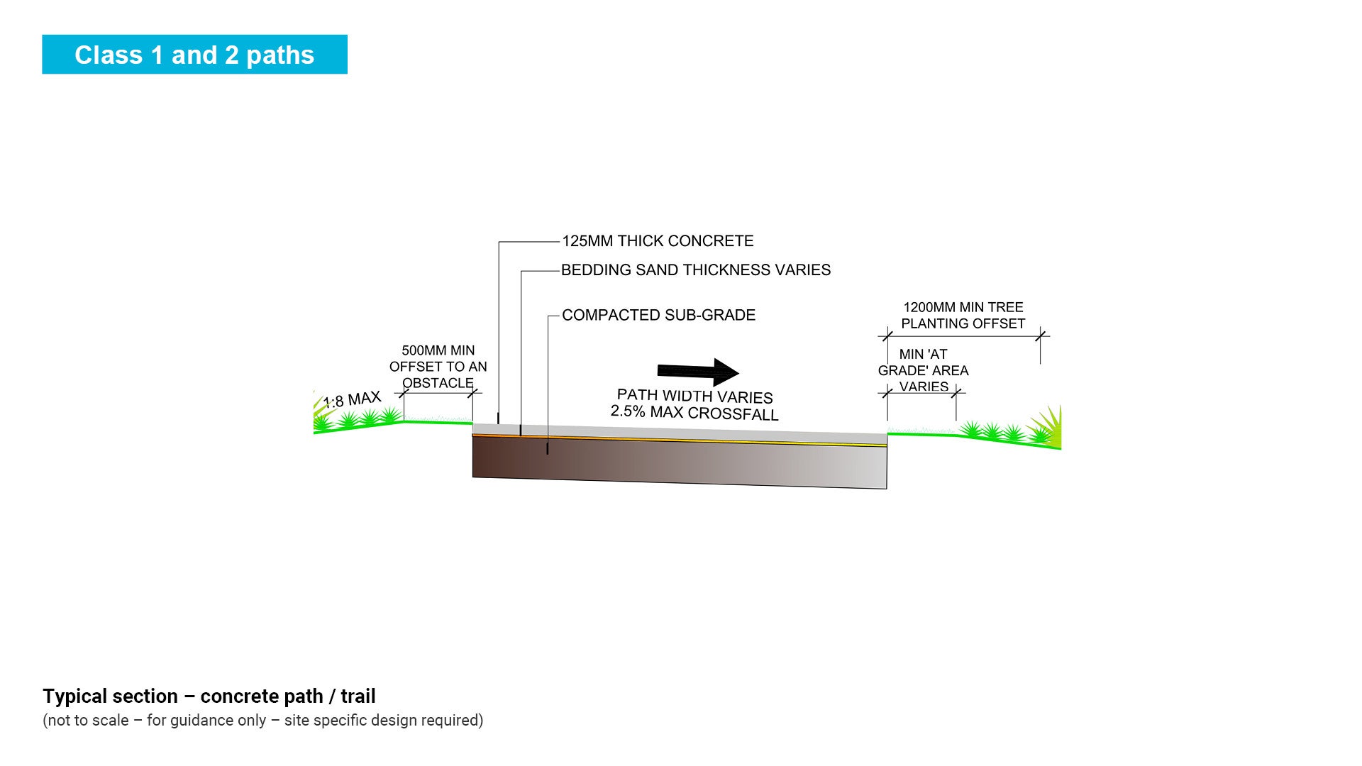
Figure 45: Coloured concrete path/trail

Table 23: Concrete path elements and key considerations
Concrete elements (path design is site specific dependent upon existing soil type) | Parks and open spaces | IPWEAQ (road reserve) | Advantages | Disadvantages | Notes |
Slab thickness | 125 mm MIN | 100 mm MIN |
|
|
|
Concrete strength | N32 | N32 | |||
Reinforcing mesh | SL72 | SL72 | |||
Dowels | 16 mm Ø HDG (SS optional) | (100 mm conc.) 12 mm Ø SS (125 mm conc.) 16 mm Ø SS |
|
|
|
Reinforcing bars | N12 | N12 |
|
| |
Control Joints - Sawn or tooled | 1/3 depth x 4.0 mm wide | 1/3 depth x 6.0 mm wide |
|
| |
Edge beam (EB) | optional | (100 mm conc.) +75 mm EB |
|
|
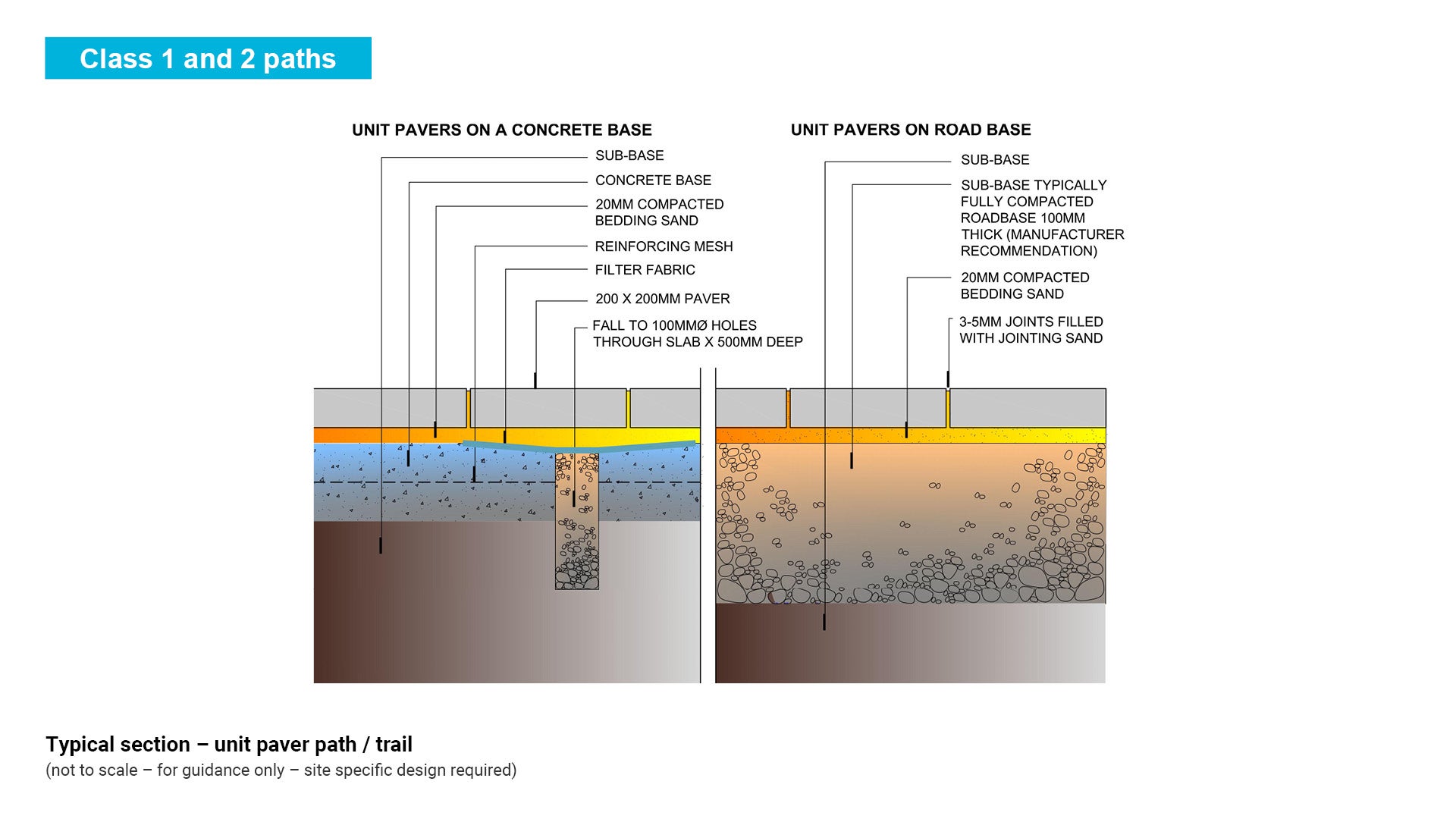
Sealed surface – unit paver
Unit paver paths can be used wherever sealed; all-weather equal access paths are required for walkers and cyclists. Unit pavers are generally Class 1 paths.
Unit pavers
- Are accessible and generally suitable for wheelchairs, mobility scooters and crutches.
- Are mainly used in commercial areas or Sunshine Coast Wide level parks due to their expense.
- Should not be provided for horses or mountain bikes.
- Are suitable for vehicle access, where designed to appropriate construction tolerances.
- May be made from clay, concrete, natural stone or handmade stone with various textures and patterns.
- Should be sealed to prevent efflorescence (the formation of salt deposits on or near the surface causing a change in appearance) Use a sealant product as per manufacturers recommendations.
- A sealant should be slip resistant to AS/NZ 4586 – Slip Resistance Classification of New Pedestrian Surface Materials.
- Are generally available in various sizes which are all suitable for pedestrian applications.
- Concrete pavers generally have a 30 year life span.
Unit paver product and design
- Bedding sand should be clean, well graded, angular sand, non-plastic, and free from soluble salts or other contaminants that can cause efflorescence. Bricklayers sand and single sized sands are unsuitable.
- Road base (granular base course) should comply with the requirements for base course for an asphalt surfaced pavement. The material may be crushed quarry material or natural gravel.
- Compaction of the base course should be not less than 92% MMDS (modified maximum dry density). Use class ‘A’ granular base material in pedestrian paving applications.
- Council prefer a concrete base for unit pavers however when unit pavers are laid on compacted road base, maintenance of underground services is simpler and rainwater infiltration is retained for tree roots.
- Joint Filling Sand should be clean, fine-graded round sand free from soluble salts and other contaminants which can contribute to efflorescence or staining. Rigid jointing compounds are unsuitable.
See Figure 46: Typical section – unit paver path/trail.
Figure 46: Typical section – unit paver path/trail
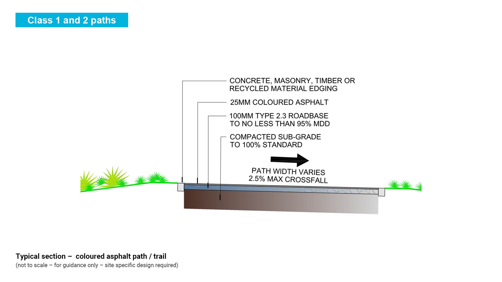
Sealed surface – asphalt (including coloured asphalt) and chip seal
Asphalt comprises a well graded non-plastic material bound with between 5% and 7% bitumen applied over a granular base material. Asphalt paths can be used wherever sealed, all-weather and easily accessible paths are required for both walkers and cyclists. Asphalt paths are generally Class 1 and Class 2 paths.
Chip seal (sprayed seal) comprises a thin layer of bitumen followed by a layer of placed stone chips which are rolled onto the bitumen. A chip seal is applied over a granular material base.
Asphalt surfaces
- Are accessible and are generally suitable for wheelchairs, mobility scooters and crutches.
- Can be used where a sealed flexible track is required for environmental reasons.
- Can be coloured to provide the opportunity to blend the path/trail with the surrounding environment.
- Are suitable for high use paths.
- Are suitable for vehicular access where designed for vehicle loads.
- Should not be provided for horses, except over distances less than 500 m.
- Are cost effective.
- Light coloured surfaces are preferred in hot climates as they radiate less heat.
- Are low maintenance and provide ease of repair and generally have a lifespan of 30 years.
See Figure 47: Typical section – coloured asphalt path/trail.
Figure 47: Typical section – coloured asphalt path/trail
Asphalt product
- Asphalt is a mixture of bituminous binder and aggregate fractions which is spread and compacted while hot to form a pavement layer. The binder is usually bitumen however polymers may be added.
- Provides a smooth hardened surface for sealing a path with a natural look.
- Both asphalt and aggregate may be coloured to provide a finish to match with the surrounding landscape or provide a contrast to it. Select an aggregate colour to match the asphalt to ensure consistency of colour as the pavement wears.
Asphalt design
- Determine the loading that the pavement will be subjected to.
- Determine the load carrying characteristics of the soil (CBR).
- Design the pavement to meet soil, loading and environmental conditions.
- Design asphalt mixture to meet loading conditions.
- Compact the asphalt.
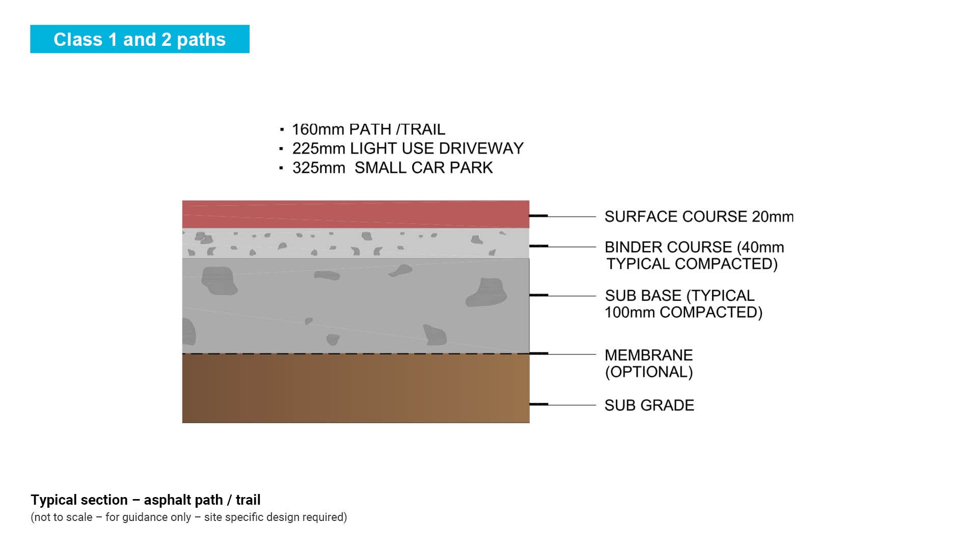
Asphalt detailed design
- For light vehicular access a minimum of 25 mm asphalt thickness over 50 mm binder course and compacted sub-base of 100 mm thick.
- For heavy vehicle access a thicker sub-base is required. A pathway will require less sub-base thickness.
- Suitable for light vehicle access (limited management vehicle access).
- For regular vehicle access, the path/trail surface thickness should increase to 150 mm to 200 mm at the vehicle crossing area and include extra layers such as road base.
See Figure 48: Typical section – asphalt path/trail.
Figure 48: Typical section – asphalt path/trail
Asphalt colour options
- Asphalt can be hot underfoot and colour should be selected carefully to provide a luminance contrast to the surrounding, while addressing aesthetic needs.
- Asphalt can be coloured, by using an oxide tint such as ‘Shell Mexphalte C’ or equivalent. This is a clear synthetic binder that can produce a spectrum of coloured asphalt.
- Alternatively you can use a two coat spray seal (e.g. Bushmates Coloured Bitumen or equivalent). Both the asphalt and aggregate are coloured which provides a finish that matches with the surrounding landscape.
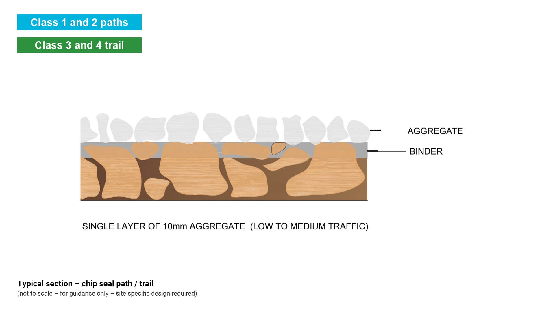
Chip seal/sprayed bitumen seal
- Is a water resistant surface formed by a layer of placed stone chips rolled onto a thin layer of bitumen which has been applied over a granular material base.
See Figure 49: Typical section – chip seal path/trail.
Figure 49: Typical section – chip seal path/trail
Modified surface – stabilised gravel
Gravel is a mix of small water-worn or pounded rocks or rock pieces. Stabilised gravel contains an additive which can increase the cohesive stability of a surface finish, while enabling the infiltration of rainwater.
Stabilised gravel paths/trails can be used wherever accessible paths are required for walkers, cyclists, horses and bush walkers. Stabilised gravel paths/trails are generally Class 2 paths and Class 3 trails.
Stabilised gravel
- May provide access for some wheelchairs and may be suitable for mobility scooters and crutches.
- Can be used where a modified trail is required for environmental reasons such as the protection of surface tree root systems, as long as no sub-base is required.
- Coloured gravel may be used.
- Are suitable for low to moderate numbers of path users.
- May be suitable for vehicular access where designed appropriately.
- Design elements such as type and degree of compaction of base material, percentage and type of stabiliser, selected gravel size, grades and cross-fall, user group, natural surface type, climatic conditions, maintenance, all play a part in the life span of the path/trail.
Stabilised gravel – product
- Stabilised gravel may be supplied as a percentage such as 1 to 3% or 5 to 10% cement to gravel ratio. The binder (cement paste) glues the gravel together to form a conglomerate.
- It is imperative that the product is compacted by roller or vibrating plate to complete the binding process. Moisture is moved to the surface by the vibrating process which in turn initiates the binding process.
- Gravel pathways may also be stabilised by construction using recycled PE (polyethylene) honeycomb shaped grid panels such as COREgravel or equivalent). The plastic grid incorporates a geotextile underlay to prevent weed growth and promote water permeability.
Stabilised gravel – colour options
- Gravels colour selection includes whites and blues through to reds.
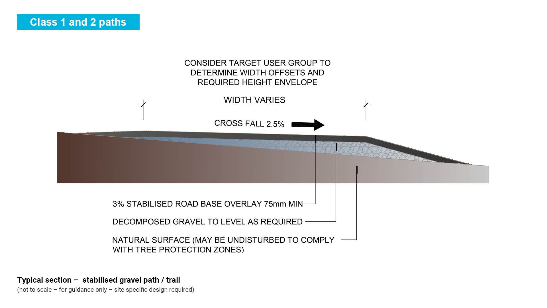
Stabilised gravel – design
- For pedestrian paths an overlay of minimum 75 mm road base mixture containing 1% to 3% cement stabiliser, depending upon site soil conditions.
See Figure 50: Typical section – stabilised gravel path/trail.
Figure 50: Typical section – stabilised gravel path/trail
Stabilised gravel – colour options
- Gravels colour selection includes whites and blues through to reds.
Stabilised gravel – design
- For pedestrian paths an overlay of minimum 75 mm aggregate mixture containing 1% to 3% cement stabiliser, depending upon site soil conditions.
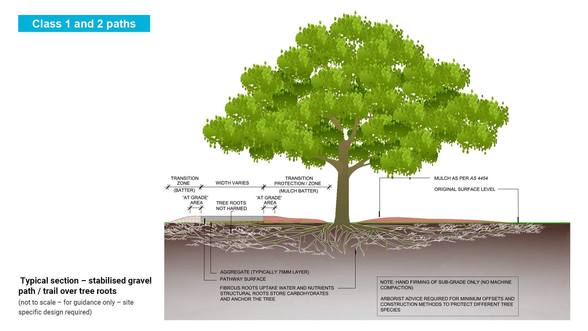
- For path/trail over tree roots a minimum gravel overlay of 50 mm and hand compaction only.
- A porous paving system which allows water to percolate through to vegetation root systems. The success of this treatment in avoiding tree root damage depends on whether there is sub-base or not.
See the following for further guidance:
- Figure 51: Typical section – stabilised gravel path/trail over tree roots
- LIM Preliminaries.
Figure 51: Typical section – stabilised gravel path/trail over tree roots
Modified surface – recycled fibre composite materials
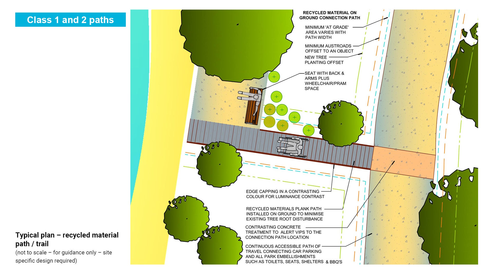
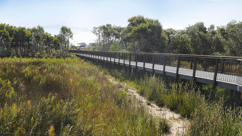
Recycled plastic and composite fibre-glass, wood and vinyl materials can be used wherever sealed, all-weather and easily accessible paths are required for both walkers and cyclists. Recycled materials paths and decking are generally incorporated into Class 1 and Class 2 paths, and may include vehicle access and pedestrian bridges.
See LIM Boardwalks and viewing platforms for raised deck options.
Recycled materials
- Recycled materials are generally equal access and are suitable for wheelchairs, mobility scooters and crutches.
- Can be used where a water permeable track is required for environmental reasons.
- Are suitable for high use paths.
- Some products are suitable for motor vehicle access e.g. recycled plastic planks turned upside down.
- Are not suitable for horses or mountain bikes.
- New product – information not available on life span at this time.
- Care is to be taken that the product used is suitable – e.g. wood plastic composite which has been saw cut may degrade when exposed to weather.
Recycled materials – product
- Is composed of recycled plastic planks and composite fibre slats as floating bearers. On ground path is recycled plastic planks laid on the natural surface.
- Are available in timber finish, grooved finish or aged timber finish.
- Compliant with AS 4586 – Slip resistance classification of new pedestrian surface materials.
- For vehicle access planks may be turned upside down.
- Combine with a composite fibre sub-structure for small bridges.
- Can be installed in shady areas, as there is no mould build-up.
- Design option available for a curved path design.
- Recommended plank span between bearers 600 mm maximum.
- Additional time may be required for sourcing of parts.
- Planks may be flammable when fuel and flame is applied directly to the product.
- Available in grey or brown.
- New product (no information at this time on colour fade).
Recycled plastic – design
- Design service by supplier.
See the following figures for further guidance:
- Figure 52: Typical plan and section – recycled plastic planks path/trail.
- Figure 53: Typical plan – recycled material path/trail.
Figure 52: Typical plan and section – recycled plastic planks path/trail.
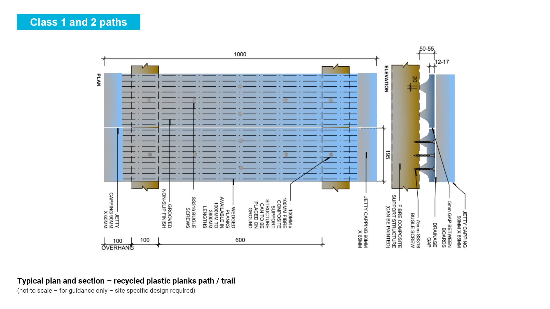
Figure 53: Typical plan – recycled material path/trail.
Modified surface – modular panel system
Modular Panel system paths/trails can be used wherever sealed; all-weather tracks are required for walkers, bush walkers and vehicles. Modular panel system tracks are suitable for Class 3 and Class 4 paths/trails.
Modular surface system
- This system is a series of modular interlinking panels specifically designed for walking paths/trails or vehicular paths/trails. It provides a firm underfoot feeling and maximum grip with the visual impact of a natural path/trail surface.
- Panels are installed in ground for pedestrian and vehicle paths/trails and may be surface installed for temporary vehicular access.
- Panels can be coloured to provide the opportunity to blend the path/trail into the surrounding environment.
- The interconnected pedestrian panel system is a hexagonal matrix pattern which delivers high levels of strength with sufficient flexibility to follow the terrain.
- Panels can be cut by hand or with power tools for neat fitting around natural features such as trees.
- Modular vehicular systems should be used for temporary vehicle access or in areas that require stabilisation such as at a vehicle beach access.
- Modular systems are to be installed as per the manufacturer’s recommendations.
- Modular systems are suitable for moderate use paths.
- They should not be provided for horse paths/trails or for mountain bike paths/trails.
See the following figures for further guidance:
- Figure 54: Typical plan – path/trail pad pedestrian
- Figure 55: Typical section – path/trail pad pedestrian
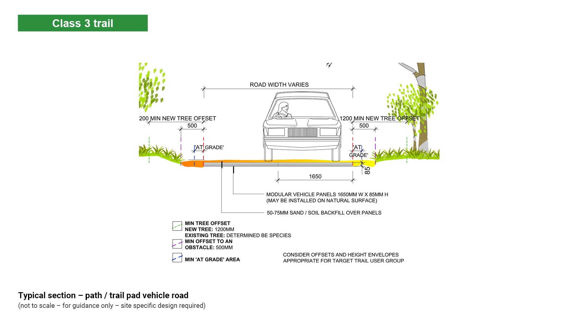
- Figure 56: Typical plan – path/trail pad vehicle road
- Figure 57: Typical section – path/trail pad vehicle road.
Modular surface system – product
- Replas – Trail Pad system for pedestrian paths (or equivalent) and Gough Plastics – Track Pad system for vehicle access (or equivalent). Modular panel material is comprised of rotationally moulded polyethylene (PE) plastic pads.
- Additional time may be required for sourcing of parts.
- Flame retardant, however will burn if a fuel source is applied and then set it alight.
- Concrete modular planks such as Rocla Perma-track (or equivalent) may be used when a raised section of track is necessary.
Modular surface system – design
- Modular recycled plastic panels may be installed on natural surface for path or vehicle access.
- The surface is able to be laid to suit curved path horizontal alignments.
- The surface is able to be backfilled with local material to preserve a natural aesthetic.
- Installation must be as per manufacturer’s recommendations.
- Available in black or may be coloured.
Modular surface system – detailed design
- Replas – Trailpad (or equivalent) is lightweight and easy to work with. It is suitable for walking path/trail installations. It can be colour matched to suit the environment or available in black.
- Replas – Trackpad (or equivalent) is lightweight and easy to work with. It is suitable for vehicular path/trail installations. Again it can be colour matched to suit the site or is available in black.
- Both systems can be permanent or temporary. Temporary solutions may be required particularly for vehicle access during construction projects or in emergency disaster situations such as flood, fire, oil spill. The product is lightweight and can be loaded and unloaded onto a truck for temporary use.
- This product has the potential to suit applications where State Government permit requirements dictate that foreshore embellishments be ‘temporary or sacrificial’ in nature.
- This product has the potential to suit applications where tree protection policies and tree surface roots or root systems determine there is to be minimal or no excavation.
Figure 54: Typical plan – path/trail pad pedestrian
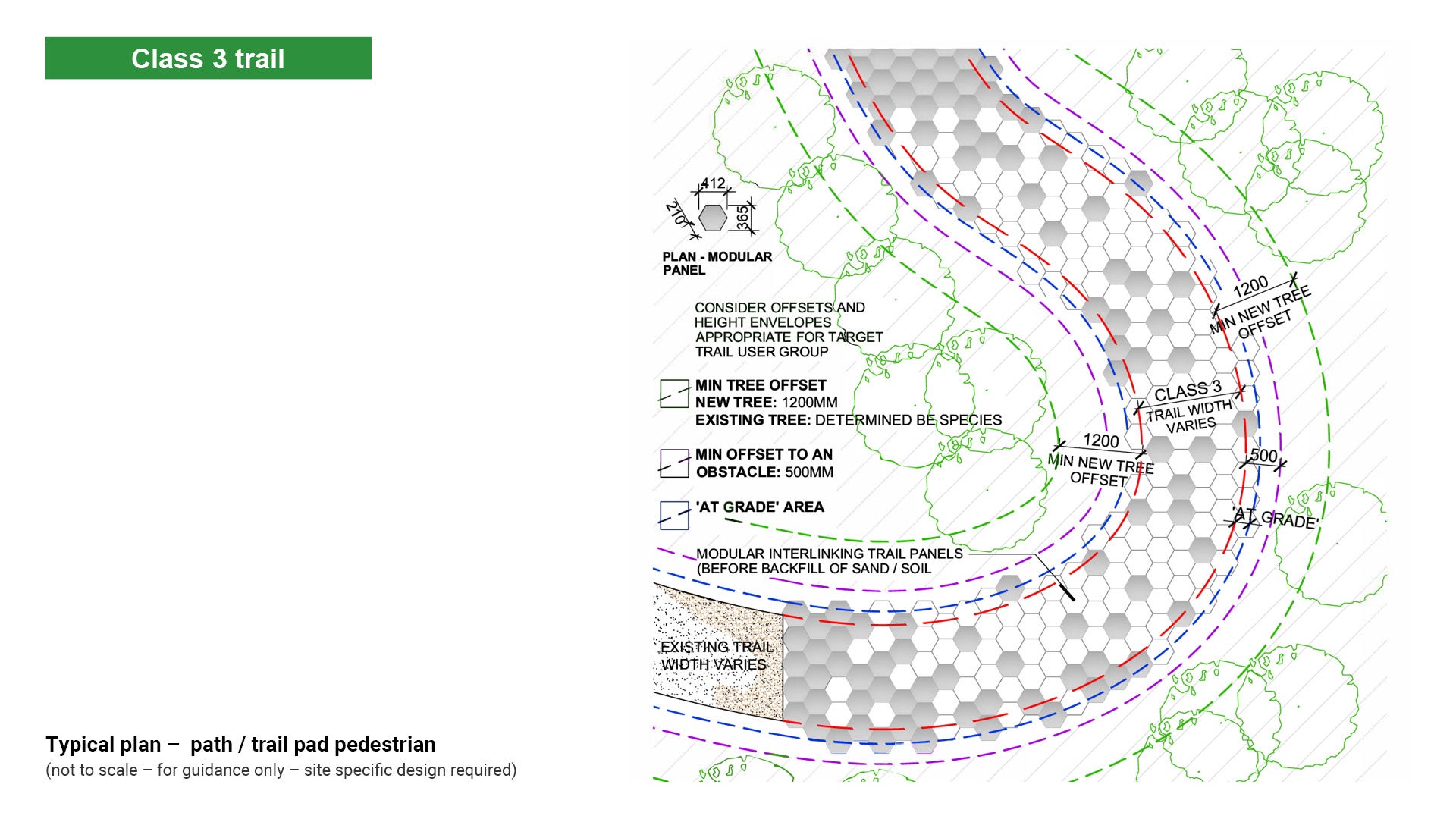
Figure 55: Typical section – path/trail pad pedestrian
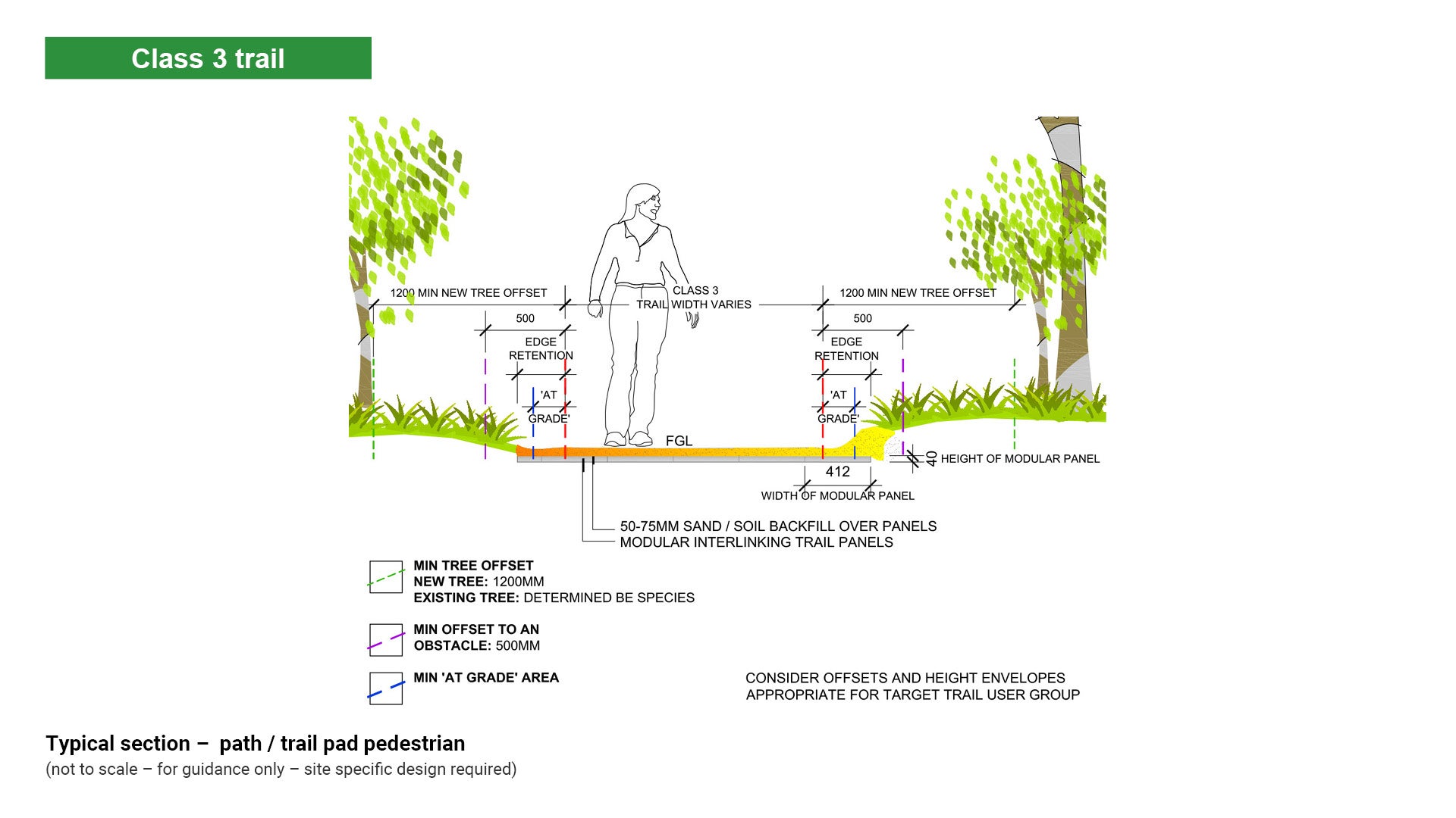
Figure 56: Typical plan – path/trail pad vehicle road
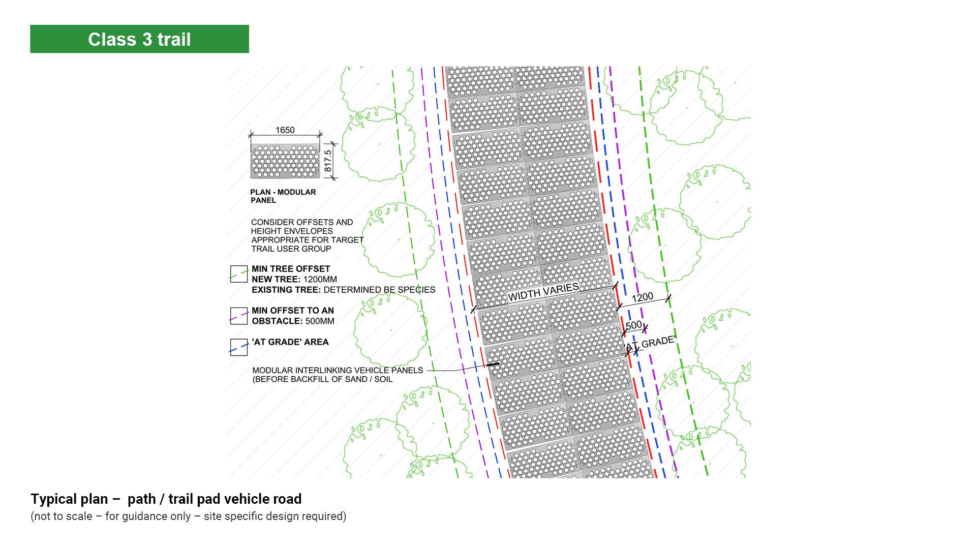
Figure 57: Typical section – path/trail pad vehicle road.
Unsealed surface – compacted path/trail/track surface at grade
A smooth compacted surface is often the most appropriate for a range of paths/trails as it provides a well-defined surface, it is relatively low cost, and it provides a firm base for users with limited experience.
The fundamental forces working upon unsealed paths/trails are compaction, displacement, erosion and human behaviour. The most significant is the effect these forces have on path/trail drainage. See LIM Landscape drainage for further guidance.
Path/trail compaction
Compaction is the process by which soil particles become increasingly dense as a result of repeated application of force.
While constructing a new path/trail, compaction of soils can be problematic for trees when existing roots grow in the zone of compaction. Hand compaction has less impact on trees than mechanised vibrating compacting plates.
See Figure 58: Path/trail compaction and displacement.
Figure 58: Path/trail compaction and displacement
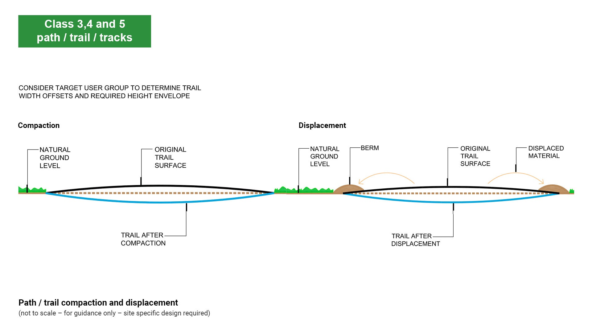
Path/trail displacement
Displacement is where soil particles become dislodged and propelled by the force of foot traffic or vehicular traffic. Over time the path/trail forms berms at the edges which may act as water dams. A path/trail designed with incorporated ridges may flatten over time.
See Figure 58: Path/trail compaction and displacement.
Erosion
Erosion is a natural process where water acts on the path/trail to carry soil particles away, creating gullies and washouts. New paths/trails are prone to forces of erosion as compaction has not yet stabilised the path/trail surface.
Older paths/trails may also be subject to erosion as compaction and displacement channel stormwater onto the path/trail.
See LIM Landscape drainage for further guidance.
General description
- Use unsealed compacted surface generally for Class 2 and 3 paths/trails.
- Where possible, use locally available or naturally occurring material compacted to produce a firm surface easily capable of accommodating target user groups.
Some options for path/trail material include:
- Option 1 – Class 2.5 road base maintenance gravel.
- Option 2 – 20 mm - 25 mm unspecified road base with a binder product such as Ecotrax by Cooee Products (or equivalent). Ecotrax is a natural food based product which when mixed with bitumen and cold water becomes a bitumen based hydrophobic binder (tends to repel water). Ecotrax can be blended into the road base or sprayed on the surface of unsealed roads and paths. Subgrade treatment is dependent upon the natural soil characteristic.
- Option 3 – Decomposed granite is granitic rock that has weathered or been crushed into smaller pieces or chunks. Decomposed granite stabilised with cement additive (1-3%) dry cement. Do not use this option on paths/trails greater than 5% or in high use wet areas.
- Coarse sand with a binding agent could be used for a horse path/trail, but this is an unsuitable surface for path/trails to be used by walkers and cyclists.
See Austroads guide to pavement technology Part 6: Unsealed pavements – the design of vehicle access roads for further guidance.
Gravel path/trail pavement options based upon CBR
- California Bearing Ratio (CBR) is a penetration test developed by the California Department of Transportation. CBR is a measure of the strength of the sub-grade and is a recognised international civil engineering standard.
- Strength of the sub-grade determines the pavement solution.
See the following table/figure for further guidance:
- Table 24: Gravel pavement options based upon CBR
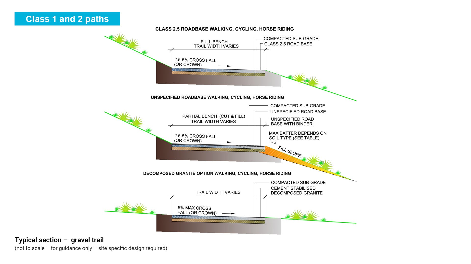
- Figure 59: Typical section – gravel trail.
Table 24: Gravel pavement options based upon CBR
Soil description | Pavement |
Compacted gravel/weathered rock | 50 mm compacted aggregate surfacing or none |
Loose gravel/sand | compacted sub-grade 50-75 mm compacted aggregate pavement |
Well compacted clay CBR 7%+ | 50-75 mm compacted aggregate |
Firm clay CBR 5%-7% | compacted sub-grade 50-75 mm compacted aggregate pavement |
Soft clay CBR 3%-5% | geo-textile over sub-grade 100-150 mm compacted aggregate pavement |
Soft organic soil CBR <3% | imported fill sub-base. Pavement to match sub-base material or boardwalk |
Figure 59: Typical section – gravel trail
Unmodified natural trail/track surface
This is the least costly and simplest form of path/trail construction. This surface is generally used for Class 3, Class 4 and Class 5 trails/tracks. It is best used on low use paths/trails where natural drainage is working effectively.
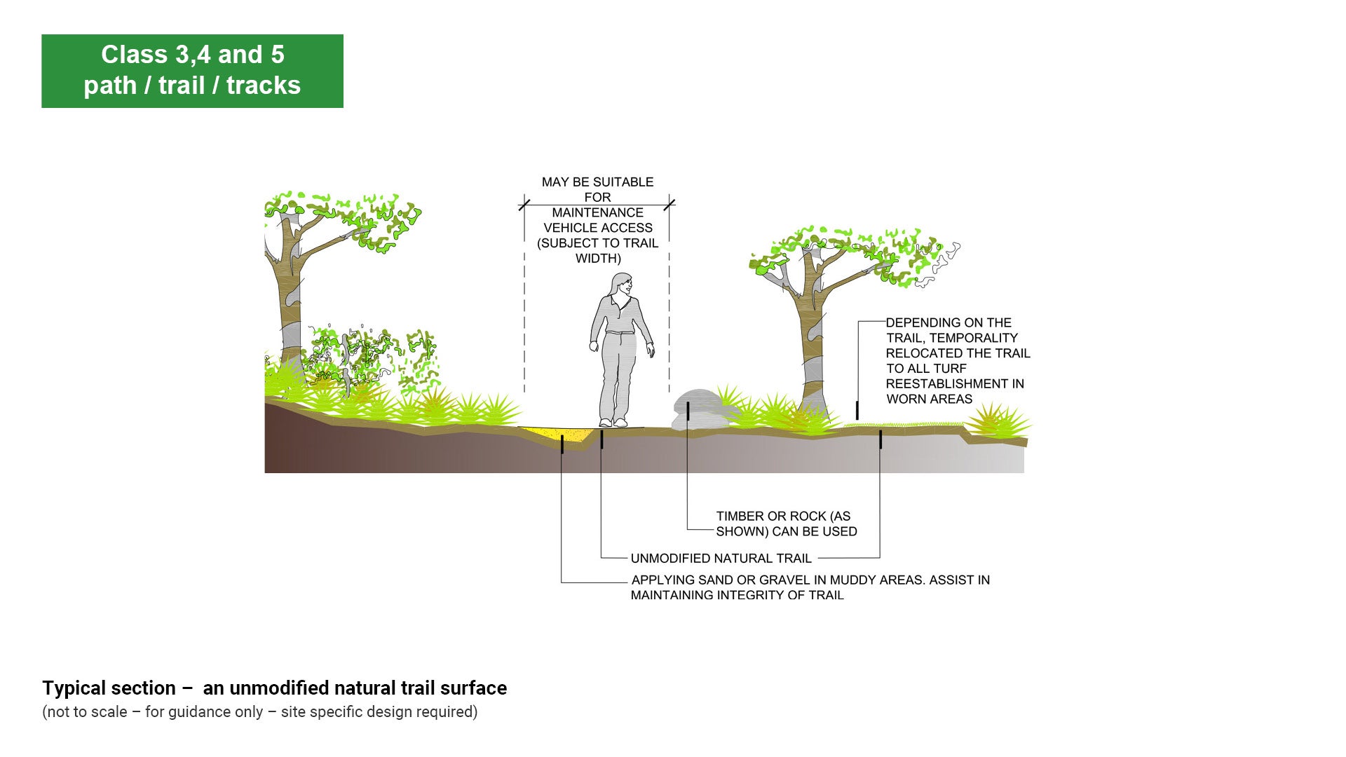
Unmodified natural path/trail surface
- Edging should be minimal but timber or rock can be used.
- This path/trail surface is subject to damage during periods of rain and intensive use. Applying sand or gravel to muddy areas may assist in the repair and prevent further damage to the surface.
- Depending on the path/trail, there may be scope to temporarily relocate the paths/trails allowing for turf re-establishment in worn areas, or allow greater setback to existing trees.
- Existing soil profile can be improved by incorporating a soil stabiliser such as Ecotrax by Cooee Products (or equivalent), a natural binder made of food based products, or equivalent. Path/trail longevity is improved and maintenance costs reduced.
- DustBloc by Cooee Products (or equivalent) is a stabilising emulsion of bitumen, water and additives which may be used for dust suppression on unsealed surfaces.
- A variation to this path/trail surface is a simple maintained grass surface path/trail. This treatment is particularly suitable for paths/trails with a high level of horse riding. A managed grass surface path/trail should be maintained with turf no greater than 200 mm height.
- Suitable for maintenance vehicle access when dry (subject to path/trail width).
See Figure 60: Typical section – unmodified natural trail surface.
Figure 60: Typical section – unmodified natural trail surface
Wet and sensitive areas
Turnpike construction provides a durable, elevated path solution for waterlogged or soft soil environments, often enhanced by geosynthetics for separation, reinforcement, drainage, and containment. Proper material selection and site-specific design ensure long-term performance and minimal maintenance.
Turnpike path/trail
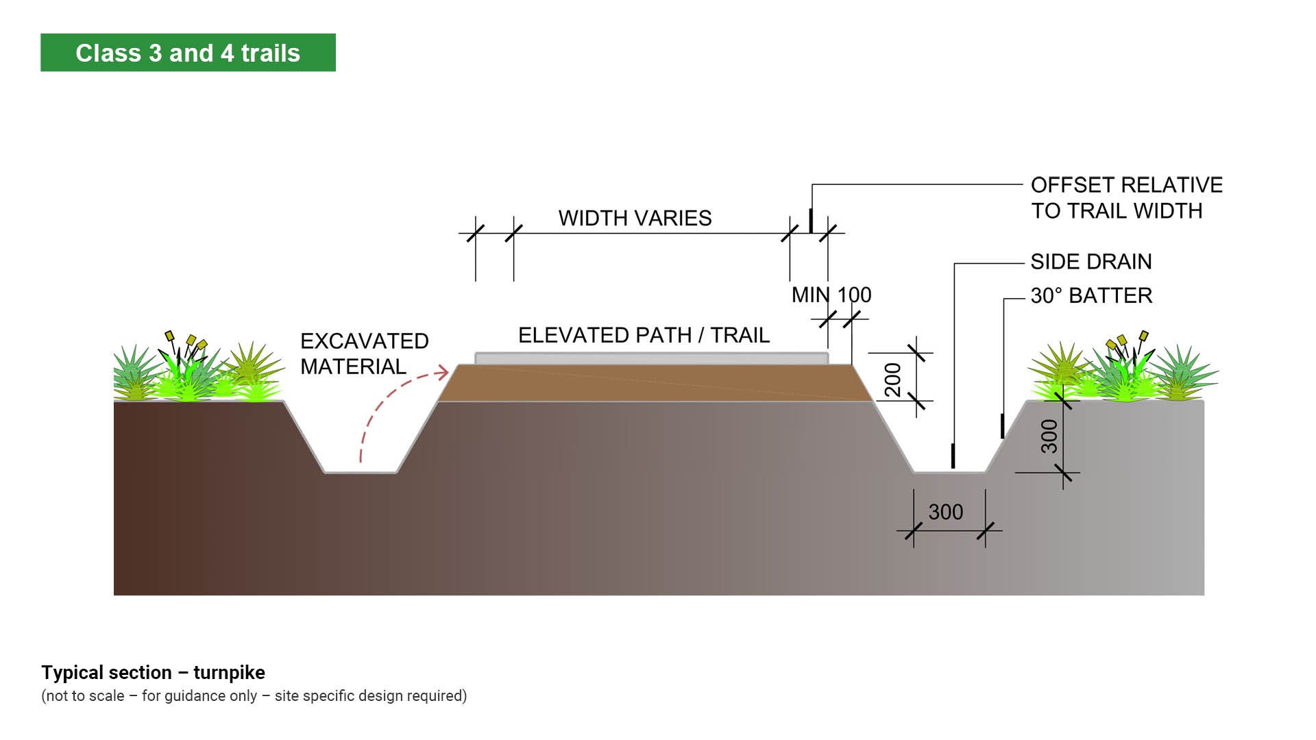
A ‘turnpike’ is a path/trail formation with raised centre tread with fill material excavated from parallel side drains and from offsite. A turnpike is a useful method to raise the path/trail tread above the water table. This creates a raised and drained soil base on which to lay a surfacing material.
General description
- Turnpikes are especially useful in low land, water logged areas, or soft clay soils and high water table areas.
- Turnpikes should be located on flat or gently sloping sites where the tread can be raised above persistent high water tables.
- This technique can be used on path/trail grades up to 10%.
- A wide formation can provide more stability when using wet soil. However the wider the tread surface, the less height obtained above the surrounding ground surface and water table.
- Turnpikes can be long lasting and require minimum maintenance. They do require a large area for construction and can be unsightly until vegetation grows back.
See the following for further guidance:
- Figure 61: Typical section – turnpike
- LIM Landscape drainage.
Figure 61: Typical section – turnpike
Stepping stones
Geosynthetics
Use of geosynthetics can increase the effectiveness of path/trail construction. This range of products is primarily used for separation and reinforcement over wet, unstable soils.
- Geosynthetics is a term used to describe a range of generally polymeric products (consisting of a polymer). Eight main geosynthetic categories include:
- geotextiles – used for separation, reinforcement, filtration and drainage.
- geocomposites – used for separation, reinforcement, filtration, drainage and containment.
- geogrid – used for reinforcement.
- geonet – used for drainage.
- geomembrane – used for containment.
- geosynthetic clay liners – used for containment.
- geofoam – used for separation.
- geocells – used for separation and reinforcement.
- Selection of a geosynthetic product is dependent upon soil and moisture conditions and expected loads.
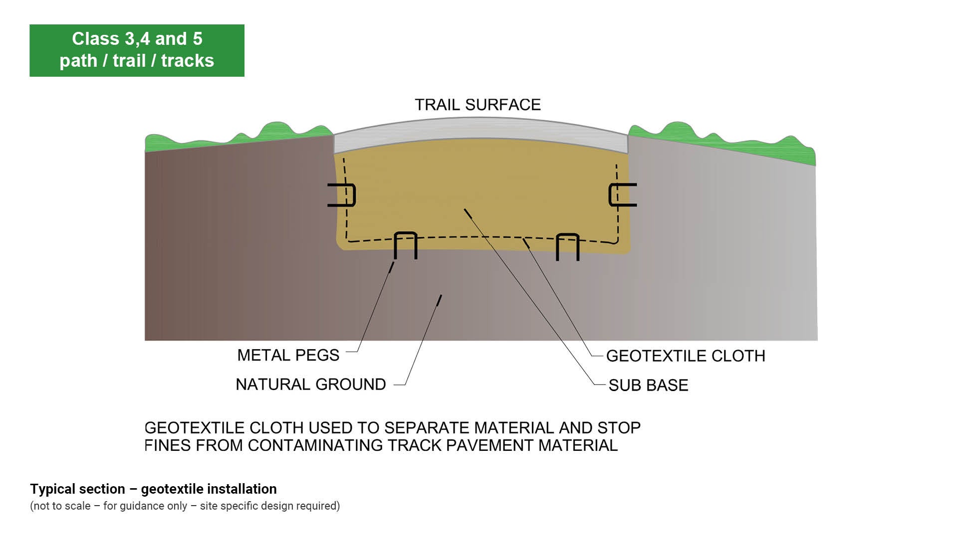
- Geotextiles can support loads and allow water to seep through while stopping soil, and may be placed directly on natural ground without prior excavation, and then covered with selected path/trail material. This can be of great benefit to existing trees.
- Separation – a geotextile may be placed between dissimilar materials so that integrity and function of both materials remain intact e.g. unpaved and paved roads.
- Reinforcement – introduction of a geotextile, geogrid or geocell into a soil to improve the total system’s strength e.g. earth walls, steep slopes.
- Filtration – is the equilibrium soil to geotextile interaction that allows adequate liquid flow without soil loss e.g. retaining wall drainage, silt fences and curtains.
- Drainage – is the equilibrium soil to geosynthetic system that allows adequate liquid flow without soil loss e.g. sports fields, canals.
- Containment – involves geomembranes, geosynthetic clay liners which function as liquid or gas barriers e.g. landfill liners, canals, tunnels and dams.
See Figure 62: Typical section – geotextile installation.
Figure 62: Typical section – geotextile installation
This component is currently in development