Suite of signs

Wayfinding equal access markers
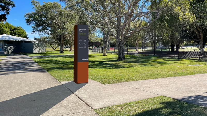
Wayfinding markers are designed as simple directional information signs, typically located at the entrance to an open space. These signs are typically designed to be read by everyone, including people with low vision.
Download the full LIM Signage suite Catalogue.
Technical drawings and artwork templates
Embellishment | Technical dwg/artwork template | Supplier |
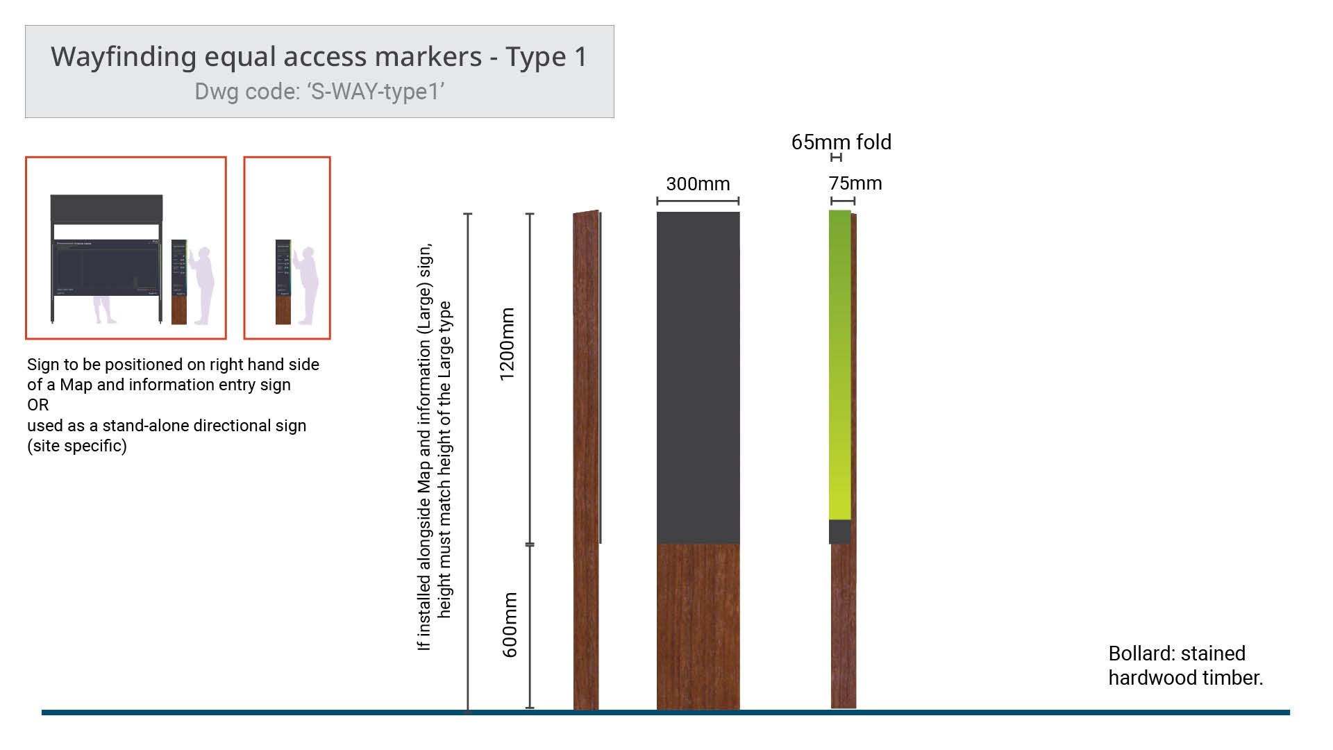 | Wayfinding equal access markers - Type 1
| No supplier specified |
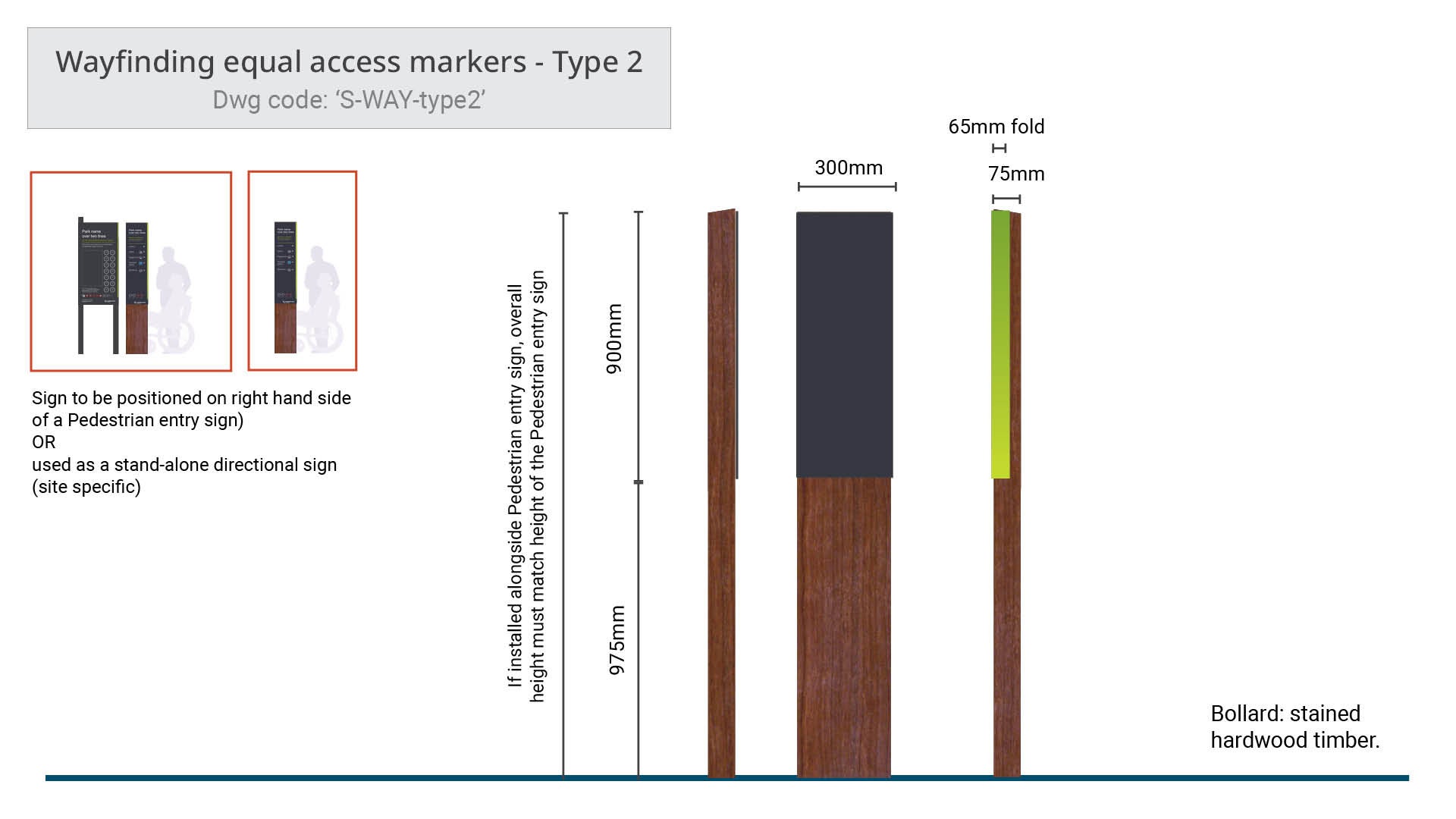 | Wayfinding equal access markers - Type 2
| No supplier specified |
Purpose
Wayfinding equal access markers are a bollard sign designed to be read by everyone and be touch read by people with low vision. The bollard may contain raised tactile lettering and or pictograms. It may also be accompanied by Unified English Braille Code (UEBC) Grade 1 for people who are blind, site specific).
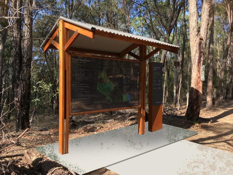
The markers can either be installed along-side and complement the 'Map and information entry sign' or 'Pedestrian entry sign' OR be installed as a stand alone sign. The content is used with the intent of minimising risk and enhancing visitor experience.
The sign is typically placed at primary entry points:
- A wayfinding equal access marker is to be installed in accordance with AS 1428.4.2:2018.
- The marker is designed to compliment the entry sign located at the entrance to an appropriate open space to direct the reader to key destinations within the site.
- The marker must be positioned on the right hand side of:
- a Map and information entry sign or
- a Pedestrian entry sign.
- may be used as a stand alone marker (site specific).
- Uniformity of installation will over time, educate people to associate this location with the wayfinding marker.
- The marker provides the site name, key attractions, with directional arrows or distances, as well as supporting approved pictograms.
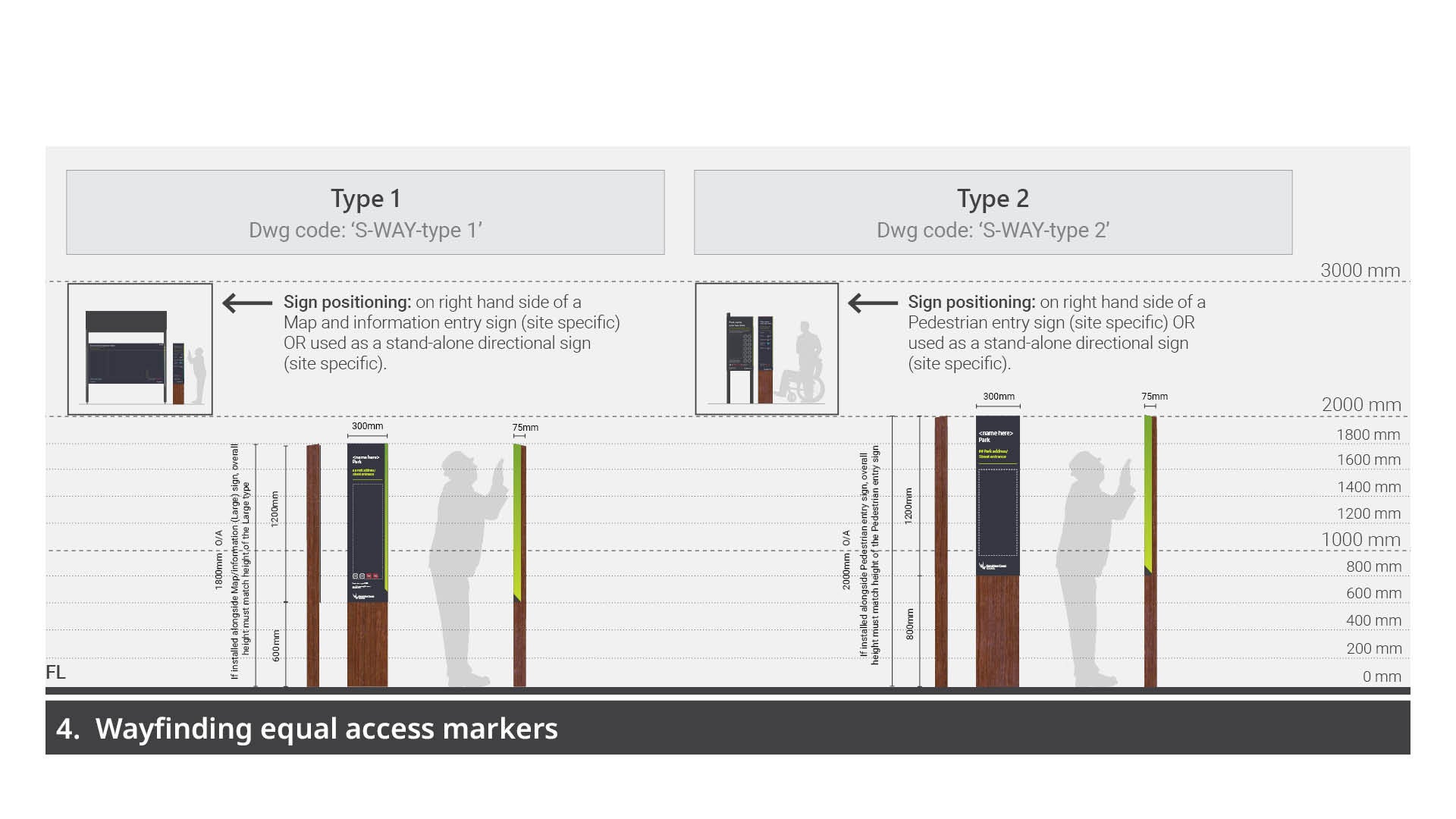
Type 1 - 1200 mm height plate - installed three ways:
- along-side a Map and information entry sign (as shown)
- along-side a Pedestrian entry sign
- installed as a stand-alone sign.
Type 2 - 900 mm height plate - stand-along directional sign only.
Planning
General
The wayfinding markers have been developed in response to the AS 1428.2.4:2018. See LIM signage suite - Overarching guidelines - Equal access for further guidance.
- The wayfinding marker contains raised tactile text or pictograms. It also may contain equivalent information in Unified English Braille Code (UEBC) Grade 1, only where a site is deemed accessible for blind persons to navigate.
- Wayfinding markers may be single or double sided.
- A double sided marker may only be considered if the accompanying an appropriate entry sign (positioned beside the marker) is a double sided sign.
- If the marker is utilised as a stand alone sign however, double or single sided may apply freely.
- The intended use of the open space must be considered to determine the use of the directional marker:
- Does the open space facilities and access cater for people with low vision and people who are blind (VIPs).
- The level at which open space caters for VIPs, will determine the number of markers required and the type of accessible design components incorporated into the marker panel.
- If the open space is deemed safe for a blind person to navigate, raised text accompanied must be incorporated. Optional consideration for increased capability, include Unified English Braille Code (UEBC) Grade 1.
- Braille must not be incorporated if the immediate open space is not deemed accessible/safe for blind people. The absence of Braille in this instance denotes that the it is not a safe navigational area for blind people.
Design
Legal, standards and guidelines, requirements
Sign construction
- Technical drawings (DWGs) - for typical construction details for each sign type. See Technical drawings and artwork templates table (above - top of page).
- Artwork templates and samples - for approved graphic design templates and samples for alternative options (where applicable) for each sign type. See Technical drawings and artwork templates table (above - top of page).
See LIM Signage – Overarching guidelines – for Standards such as, designing for access and inclusion, traffic and road standards (where applicable).
Content and corporate branding
- Sunshine Coast Council corporate branding logo must be displayed on all signs as per Artwork templates.
- All colours must be selected from the Council corporate colour palette or otherwise approved for specific purpose. e.g. some colours, such as red, yellow and black, (not part of the corporate palette) may be used for regulatory purposes.
See LIM Signage – Graphic design guidelines – for essential guidance on components that make up signs. e.g. colour application, pictogram integration, text sizing and spacing, map implementation etc.
Markers must be positioned at optimum heights (1.2 m - 1.7 m above finished surface level) to be read by touch, by people with low vision and people who are blind.
Content general
- All sign artwork is to be professionally designed (by a qualified graphic designer or equivalent) as vector files.
- Sign content must be accurately researched and approved by council asset custodian prior to print.
- The name of the reserve/park must be clearly displayed at the top of the sign. This information may be vital in emergencies.
- Reserve/park name and spelling must be checked against council records to ensure accuracy.
- All regulatory pictograms must be approved by Council (Community Response) prior to printing.
- Corporate branding banner
- Option to provide Raised tactile and Unified English Braille Code (UEBC) Grade 1 (where applicable). This would remove the need to install an Equal access wayfinding marker, however this is not preferred.
- The Braille must be a height of 6.0 mm. This international standard enables a person who is blind to run their finger over the Braille alphabet and interpret in one continuous sweep.
- The UEBC, it must be positioned directly below the corresponding raised tactile text.
Positioning
General
- When considering potential sign locations, avoid positions where the sign may interrupt or block a prominent view. Signs should be secondary to a natural view. However, safety is paramount.
- To ensure a sign panel will not be obscured in future, consider mature size of surrounding vegetation.
- To protect trees from potential damage, all signs should be installed outside of their canopy areas (drip lines). Where this is not possible, the Project Arborist should be contacted to provide advice. See LIM Site set up (including Tree protection) for further guidance.
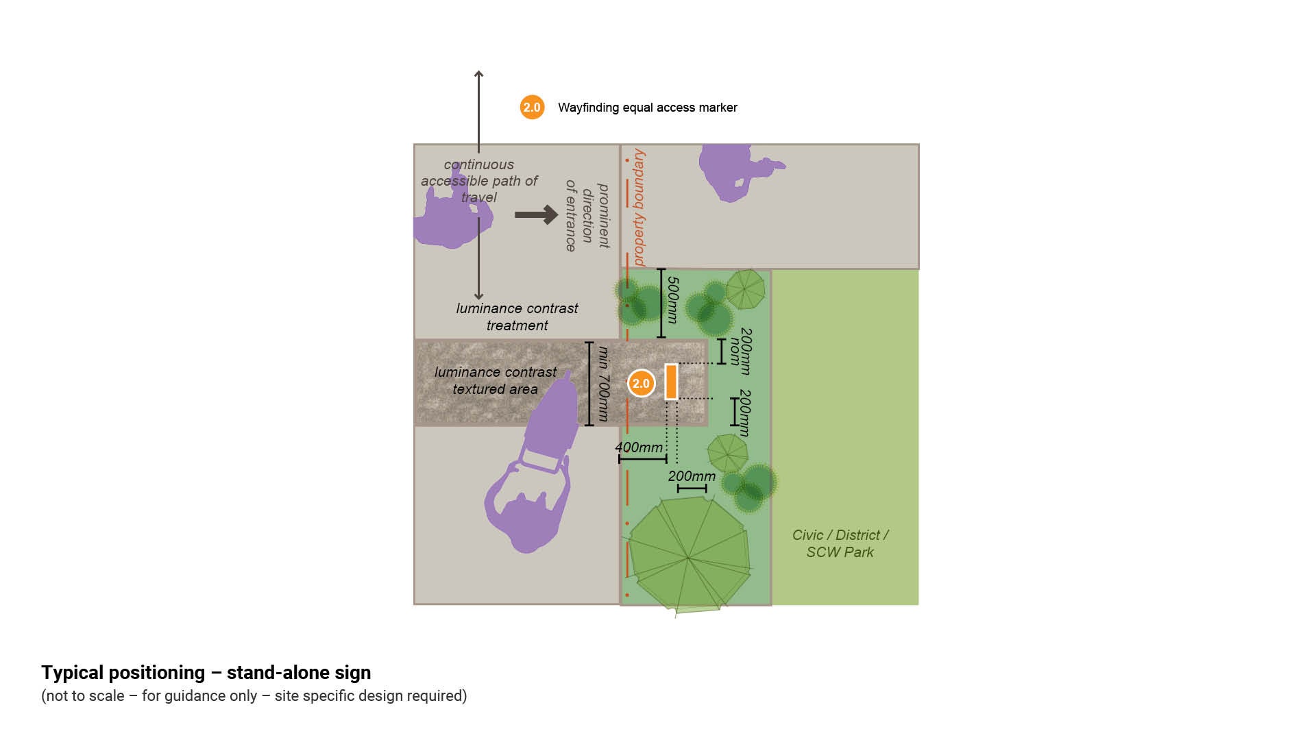
- If a pathway is less than 2.0 m wide, an additional slab or compacted surface treatment is required when a sign is installed. This provides an area for reading the content of the sign while not obstructing the path of travel. (Required for longer message signs).
- For new paths, a coloured textured treatment is recommended to form the sign slab and must extend the full width of the continuous accessible path. This treatment creates a visual and physical cue to an accessible sign location. (Required for longer message signs).
- Where there is an existing or new pathway, all signs must meet Austroads minimum 500 mm safety offset from any path edge, to avoid collision with the sign while using the pathway.
- Position signs a minimum of 200 mm in from any slab or compacted surface edge for mowing offsets (where applicable) and visual appearance.
- Allowance for deck mowers (where applicable) – 2.5 m clear area around embellishments (where possible) and avoid creating small, difficult to mow areas.
Additional requirements
- When considering installing a wayfinding marker, decide if the destination/s are accessible via a continuous accessible path of travel.
- The marker must be installed to the right of a open space entry sign or as a stand alone sign. People with low vision and people who are blind will become accustomed to the marker location, which in turn will aid in navigation of other parks and reserves which apply the same standard.
- In accordance with AS 1428.4.2:2018, to enable the sign to be read by touch, a minimum reach space of 325 mm is required in front of a sign containing raised tactile and Braille. (Females 325 mm, Males 400 mm). See Figure 11.
- Where a sign is installed beside a new pathway, a luminance contrast textured treatment (such as coloured exposed aggregate) is recommended to form the sign slab and must extend the full width of the path of travel. This treatment creates a visual and physical cue for people with low vision and people who are blind to identify a sign adjoining a pathway.
- The marker must be positioned a minimum 200 mm from the right hand side of the supporting accompanying entry sign.
- They may be used as stand-alone signs in the following circumstances:
- Where a section of the open space requires additional wayfinding direction signing.
- In place of a Map and information sign or Pedestrian entry sign (stand alone sign).
- At decision points accessible to aid people with low vision and people who are blind.
- To identify the conclusion of an equal access pathway. The marker can be installed to identify changes to a pathway. E.g. to prevent people with low vision and people who are blind, from venturing into potential hazard trail areas, such as, trails that contain uneven surfaces, narrow sections, steps and steep climbs.
See the following for further guidance:
- Figure 10 Typical positioning – install with a typical Map and information entry sign
- Figure 11: Typical positioning – install with a typical Pedestrian entry sign
- Figure 12: Typical positioning – stand-alone sign.
Figure 10: Typical positioning – install with a typical Map and information entry sign
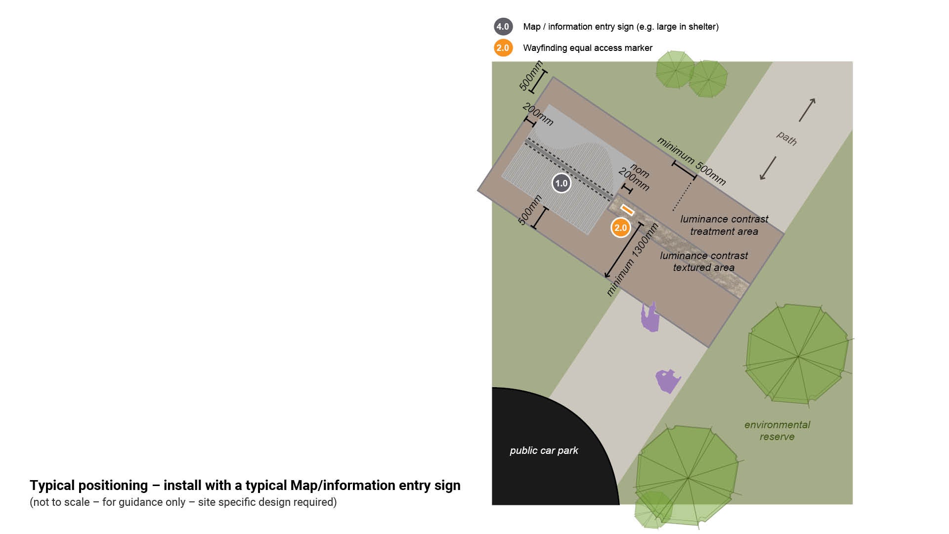
Figure 11: Typical positioning options – install with a typical Pedestrian entry sign
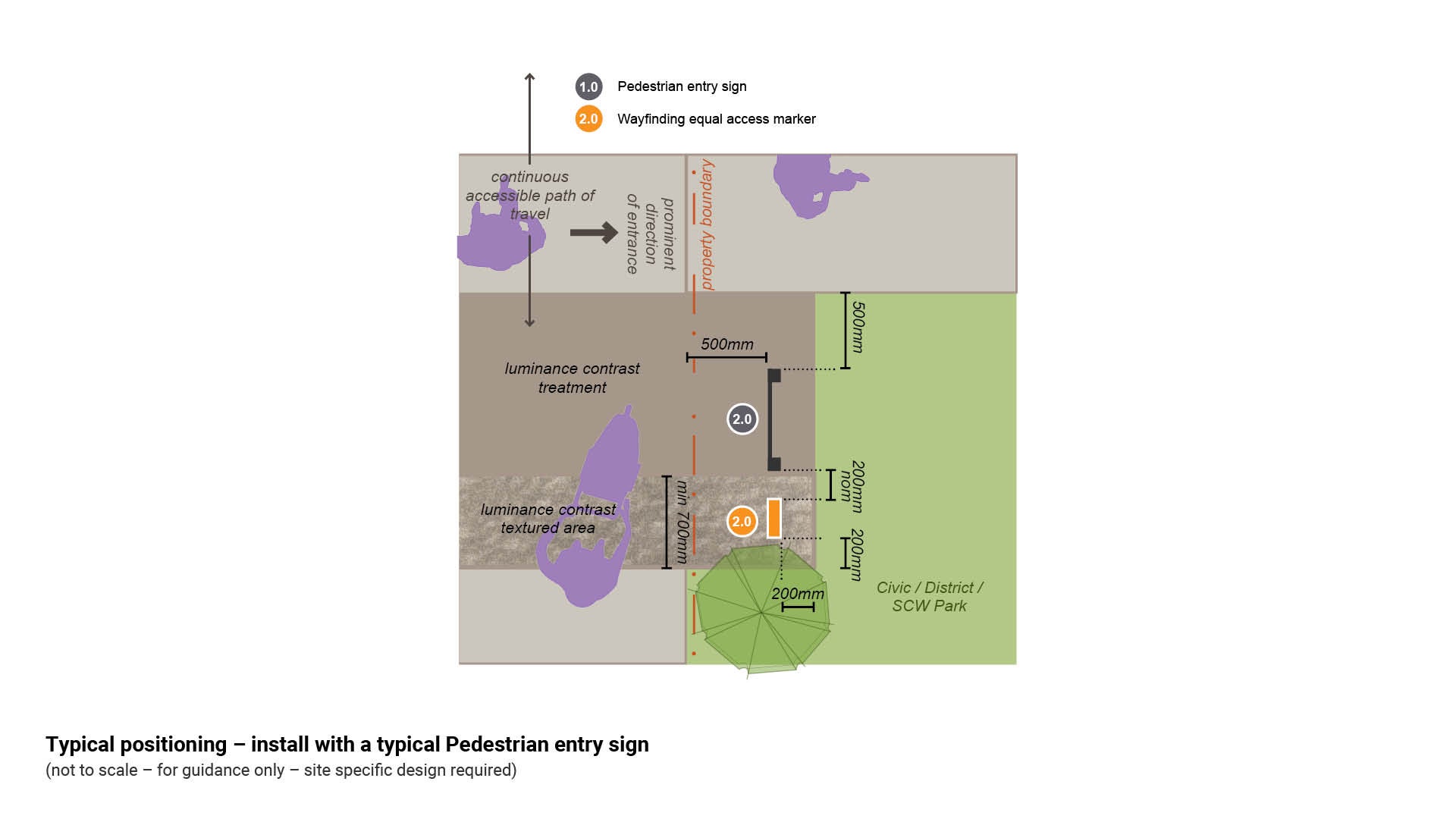
Figure 12: Typical positioning options – stand-alone sign
Delivery
For all developer delivered assets, contact Council (Development Services) – this includes all works associated with any development application.
For all council delivered assets, the following process should be used:
Site investigations
- Confirm council land tenure and approval process.
- Identify sign location.
- Identify physical/technical constraints.
- Obtain arborist advice (where required).
Community engagement/stakeholders
- Where applicable.
Corporate liaison and approvals
See the Technical drawings and artwork templates table in each sign type page for guidance - How to place an artwork order (internal use only) and Artwork design instructions (internal use only).
- Council (Parks and Gardens) and or Council (Environmental Operations).
- initial approval for use/application of sign.
- approval and guidance of artwork content.
- approval to manufacture signs.
- approval of location of signs.
- Council (Community Response)
- approval of any regulatory signage/componentry.
- Council (Communication)
- editing of templates
- supply of proofs for approval
- approval of corporate branding.
Deliverables
- Site plan – for sign installation.
- Technical drawings (DWGs) – sign construction details.
- Schedule of signs.
Manufacture
See the Technical drawings and artwork templates table in each sign type page for guidance - How to place an artwork order (internal use only) and Artwork design instructions (internal use only).
- In-house manufacture – Council (Transport Network Operations) - Civil Operations (Signs Technical Officer).
OR
- External manufacture – select a suitable sign fabricator.
Installation
- All relevant key stakeholders are to be notified (including contractors), and where required, attend a pre-start meeting.
- Sign location as per approved site plan.
- Installation as per technical drawings and schedule.
Finalisation
- Assets captured.
- As designed as constructed drawings (ADAC) supplied.
- Hand over to asset custodian.
This component is currently in development